jeffrey.kissel@LIGO.ORG - posted 21:12, Thursday 31 July 2014 (13131)
H1 SUS PR2 -- More Evidence of Bad In-vac Cabling, but it's the Sensors
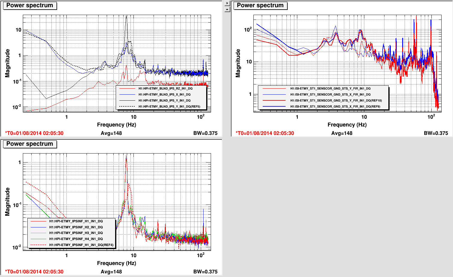
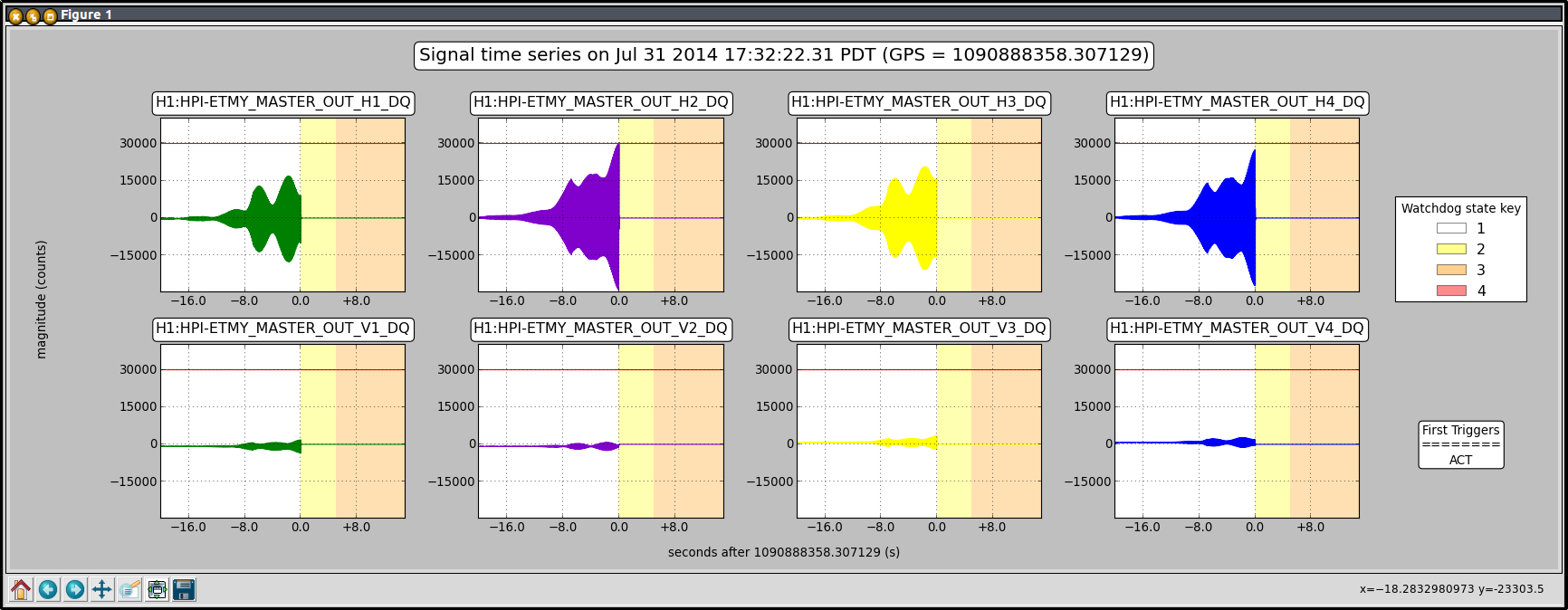
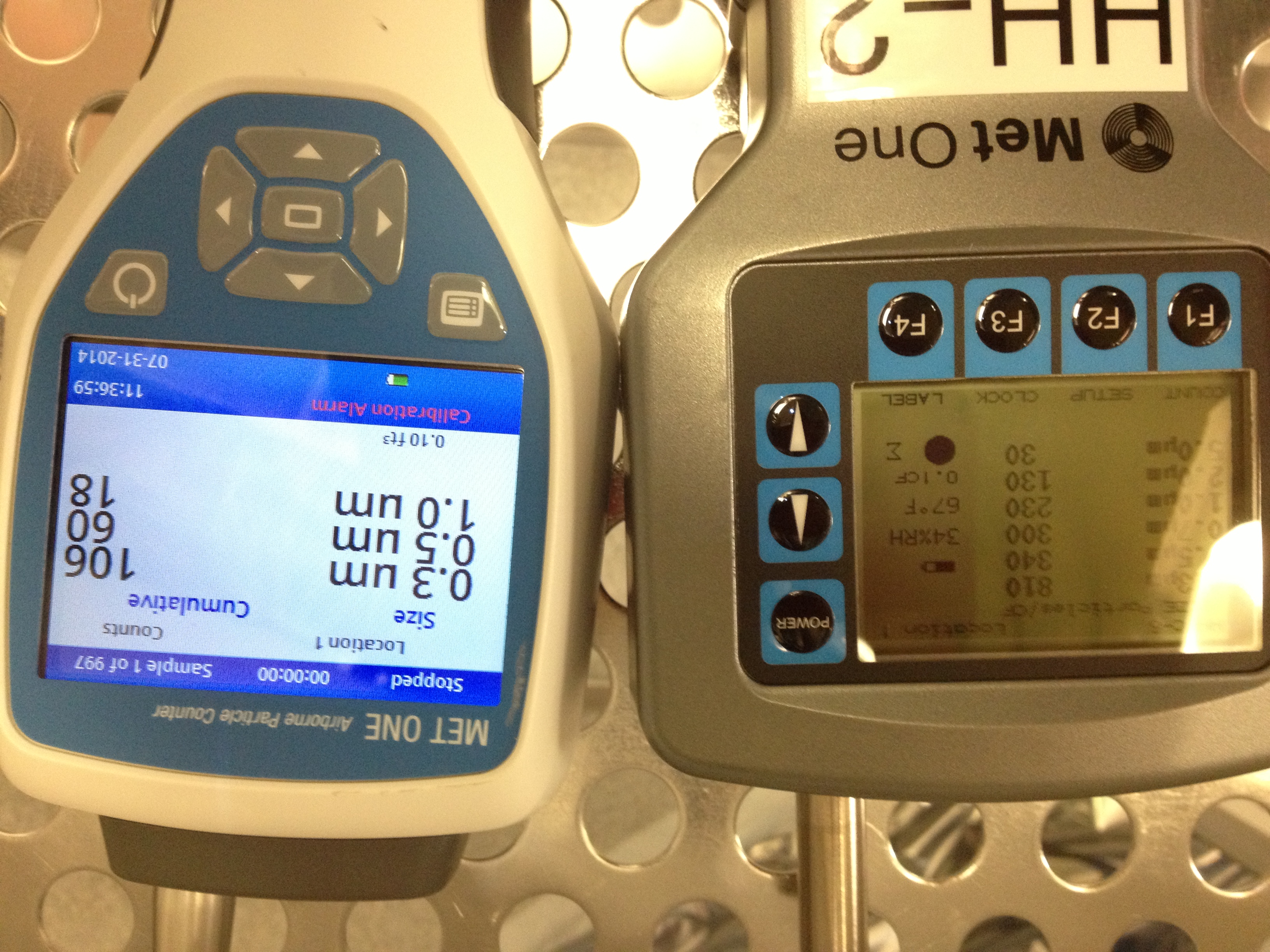
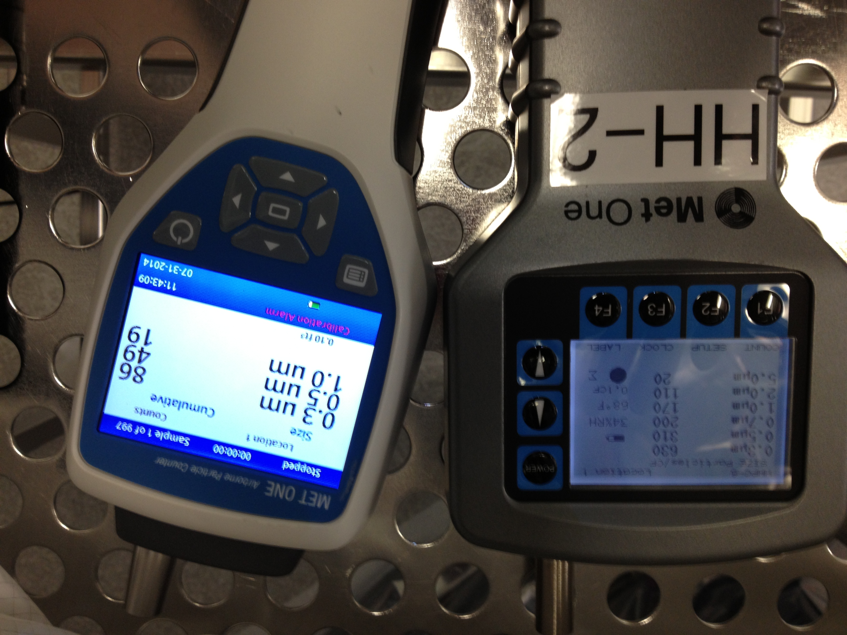
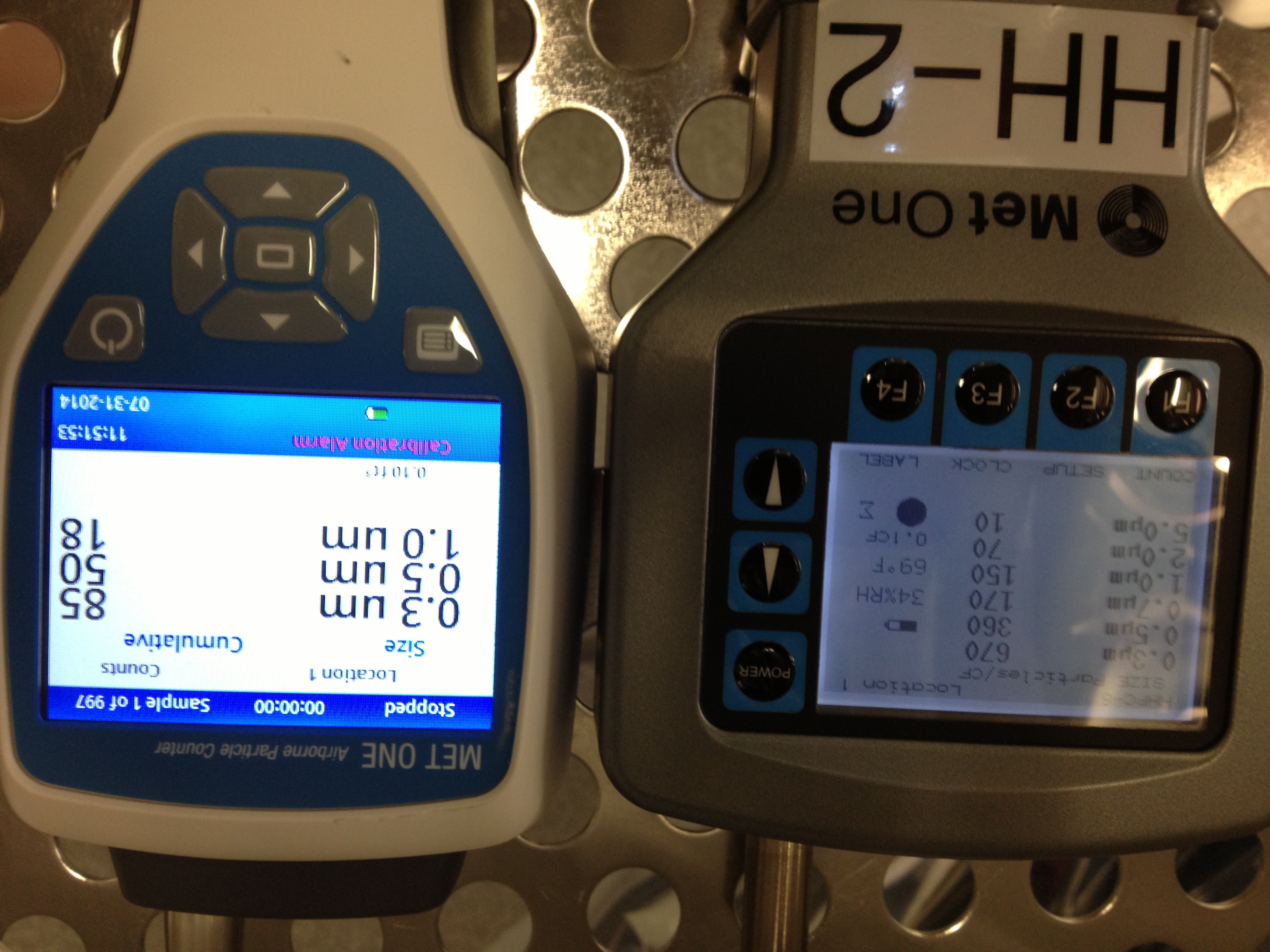
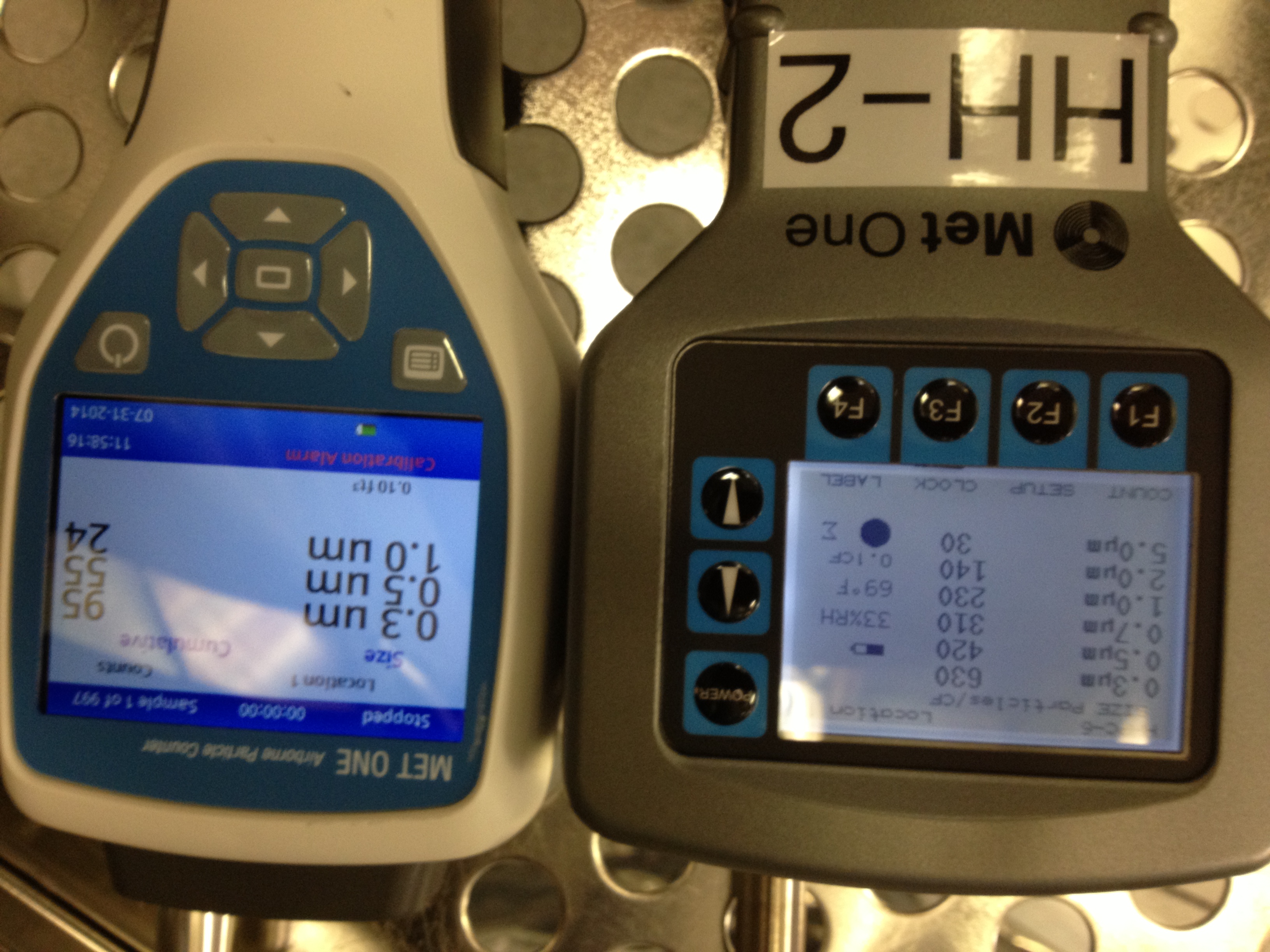
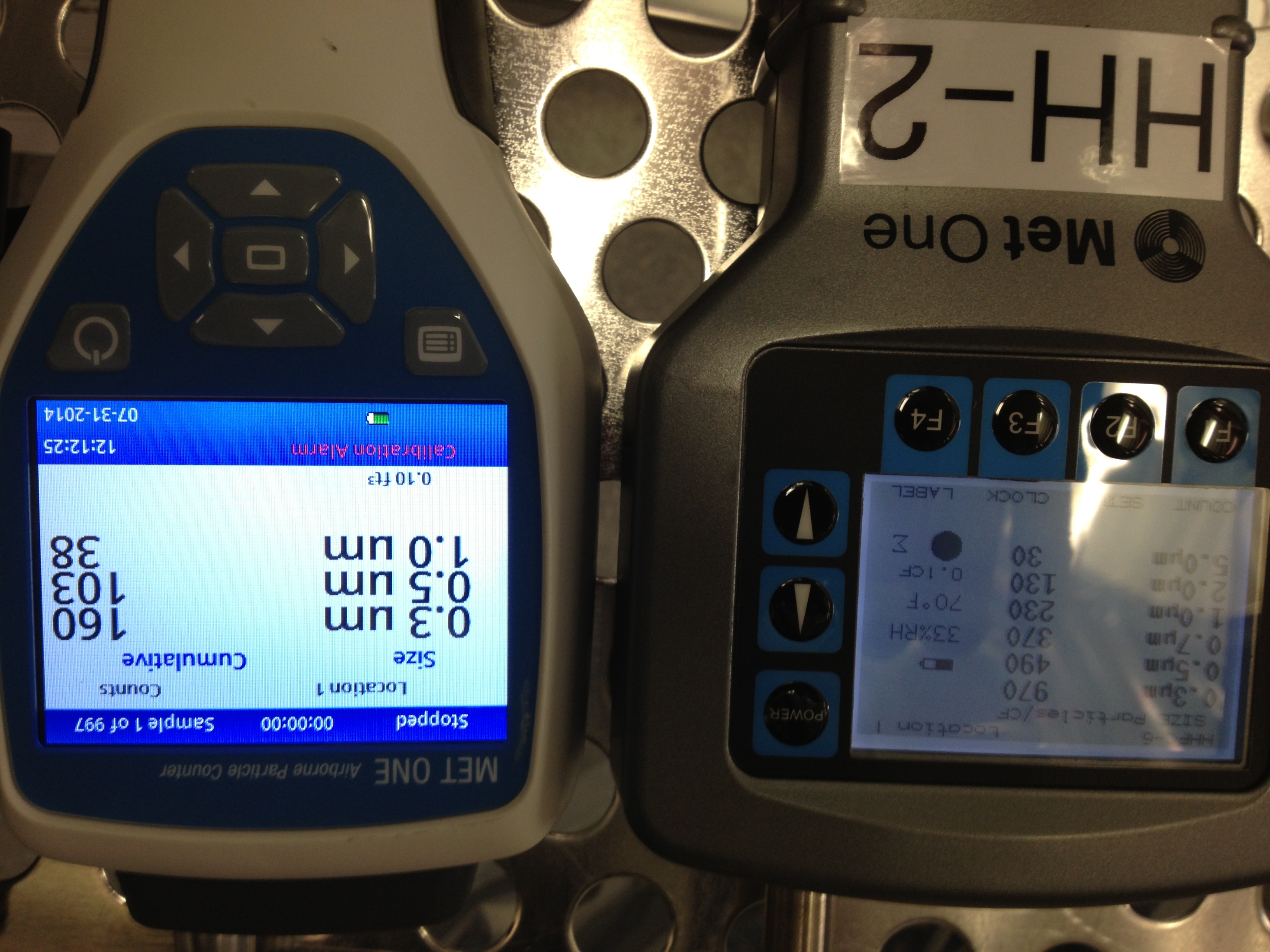
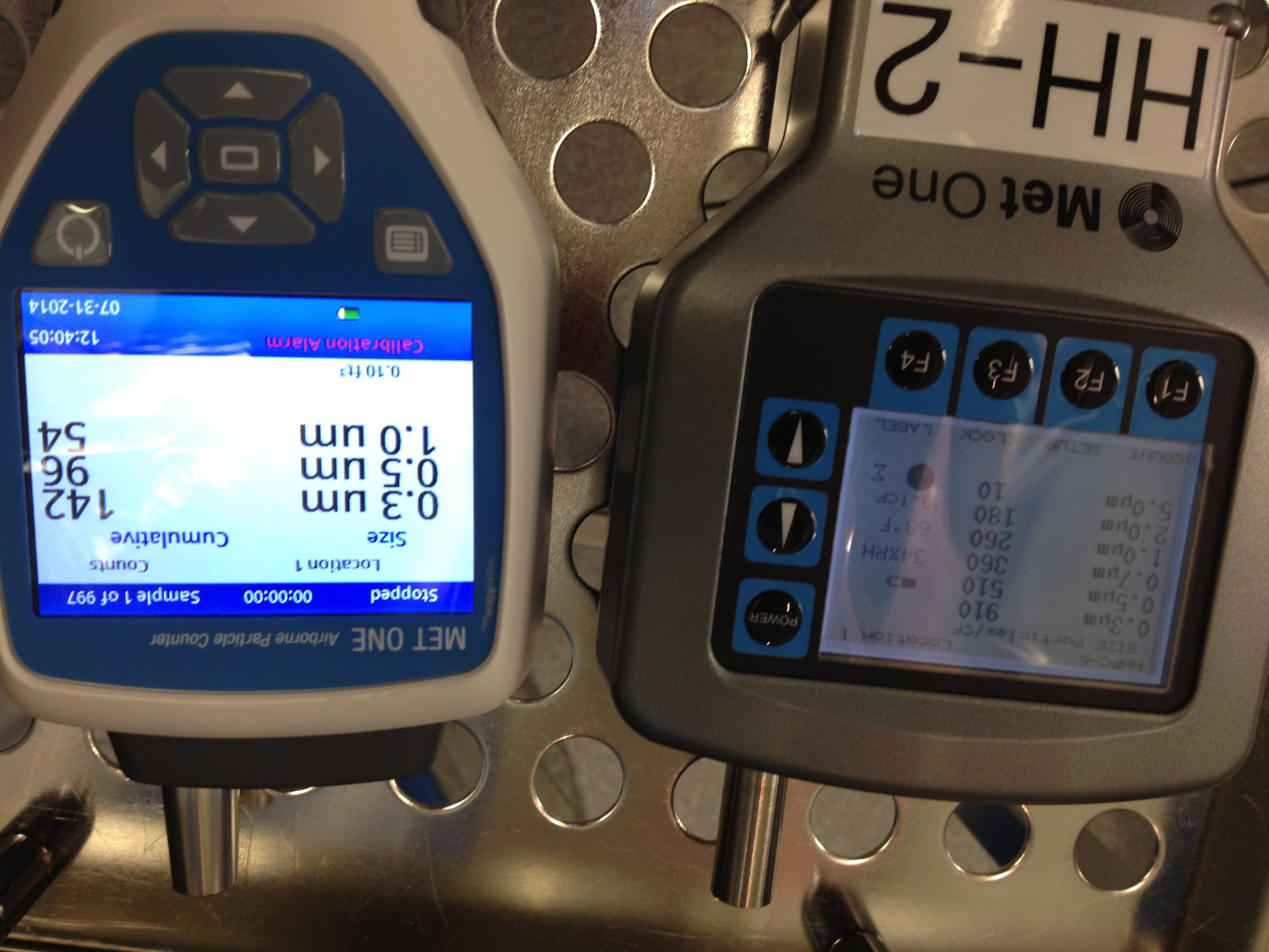
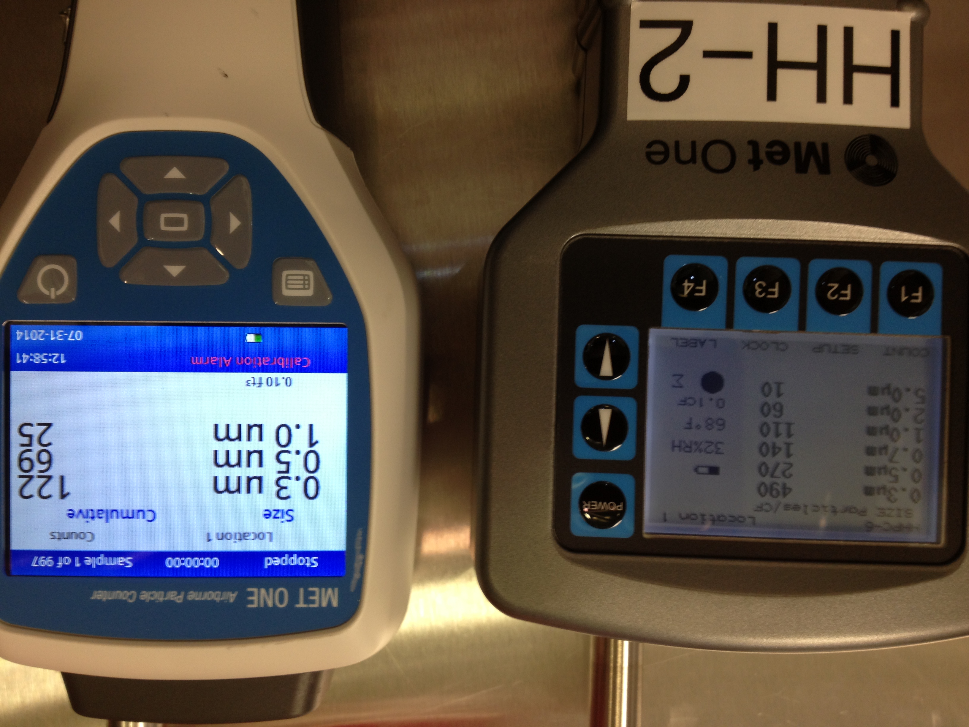
J. Kissel, A. Pele, S. Aston, N. Robertson

Not too much more information here that we don't already know, but I think I've convinced myself that the badness we see on H2 SUS PR2 is *only* a function of the OSEM sensor, and not the actuator -- end hence it's just an exaggerated high-frequency turn-up that we've seen in every other OSEM to OSEM transfer function, and it's caused by the in-vacuum part of the signal chain. Since we don't use the *sensor* side of the OSEM for any active feedback, and we have no evidence the *actuator* side is broken, we should *NOT* need to go back in chamber to fix the cabling this vent.

The new evidence, and summary of old evidence:
- I've used the test-point versions of the OSEM Basis channels, such that I could probe the transfer function behavior out to 5 kHz. Also, I plot the phase coherence, and the other OSEMs. If the suspension was actually being driven that much at 45.25 [Hz] (i.e. it was an actuator problem), then the other OSEMs should definitely have coherent response. This was already proven when Arnaud drove L, and so only LR respond badly (see LHO aLOG 13026). Another feature also appears at 787 [Hz] -- not a multiple of 45 -- and really not indicative of anything other than the in-vacuum signal chain is busted. We know it's the in-vacuum cabling, because the badness stays with the port when external cables are swapped (see LHO aLOG 13087).

- I've compared PR2's M3 spectra to several other HSTS M3 stages. Stuart only looked up to 50 [Hz] (see LHO aLOG 13106), but looking out at high frequency, PR2 should all sorts of crap in every M3 channel. All other SUS at which I looked show a nice, super clean noise floor save the expected violin modes at 350-400 [Hz] (at though sadly increasing above 1 [kHz] as roughly f^2). I had thought, briefly, that this PR2 feature was the highest Roll mode (modeled at 40.3 [Hz]), but Norna convinces me that, for a SUS whose other modes line up to within 1-2%, its unreasonable that only one mode would be off by 12%. Further, one would see such physical motion in all 4 of the OSEMs, and one does not here. Also, no other suspension sees any such feature at that frequency, and at LLO, their LSC_MC filter bank (in the IMC length control feedback path) has a roll notch at 40.9 [Hz].

Our best guess at the source of this problem in-vacuum shorts or poor cable connections caused by all the activity in-and-around the chamber during this summer vent.
Non-image files attached to this report