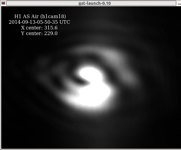
Centering: Done.
I continued the POP sled centering this morning and now it's good (see yesterday's entry on the same subject: https://alog.ligo-wa.caltech.edu/aLOG/index.php?callRep=13890).
I ended up moving both PIT and YAW by large amounts. Though the picomotor count is not realiable as a reference (because it has hysterisis and because the software sometimes skips the counting for some reason), just to see how much I moved, I show those numbers anyway.
|
|
Pico A (X, Y) |
Pico B (X, Y) |
|
Before I started yesterday |
(-331, -28257) |
(4151, 20661) |
|
After I was done today |
(4715, -37442) |
(12565, 24185) |
|
Difference |
(5046, -9185) |
(8414, 3524) |
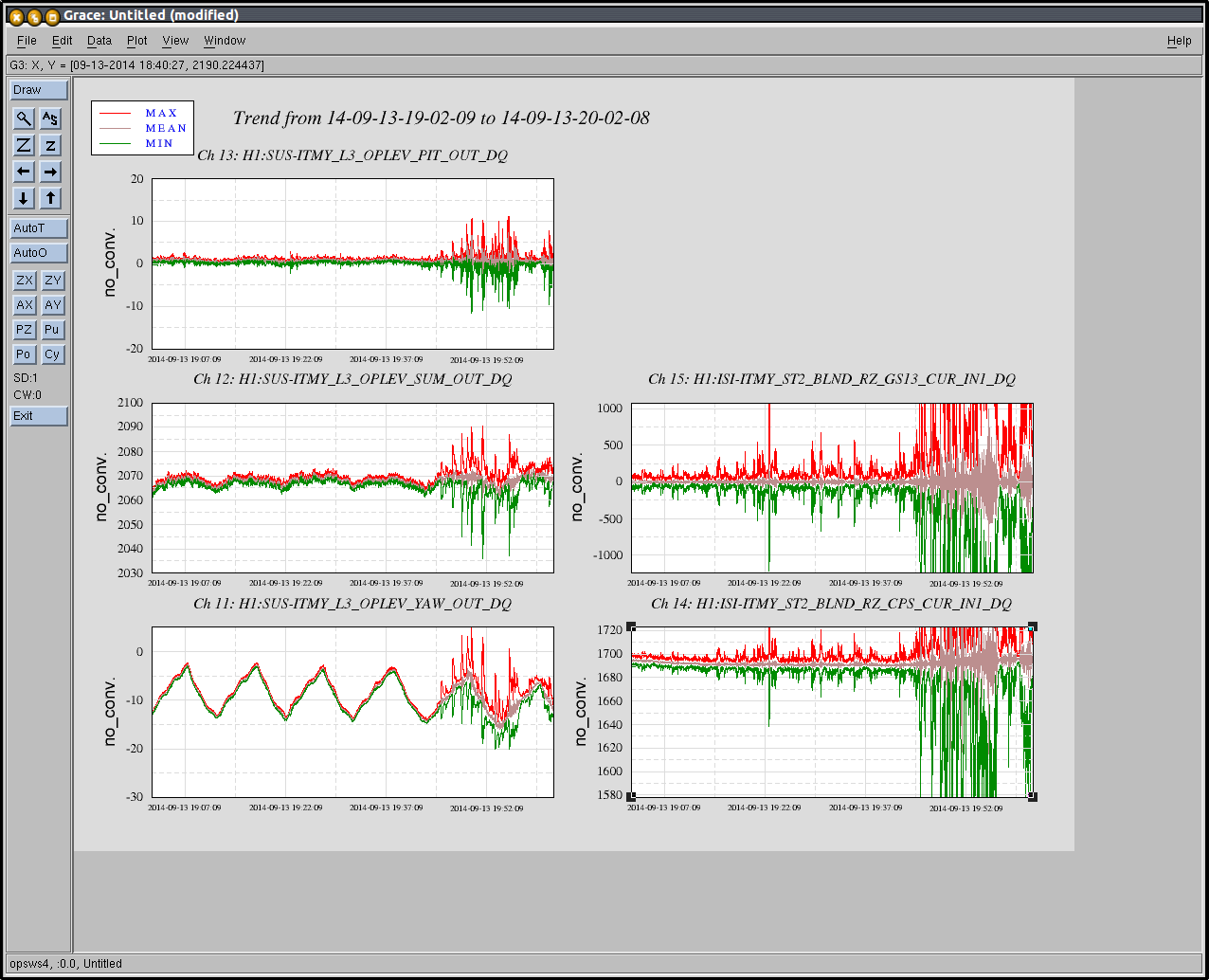
With the whitening gain of 45dB, QPDA and QPDB SUM (raw counts) were 1595 and 1463 counts on average for a straight shot beam, while we expect 1540 for both assuming 10W through IMC (it should be more like 8W in reality), so the measurement is somewhat larger than expectation but is still quite consistent with expectation.
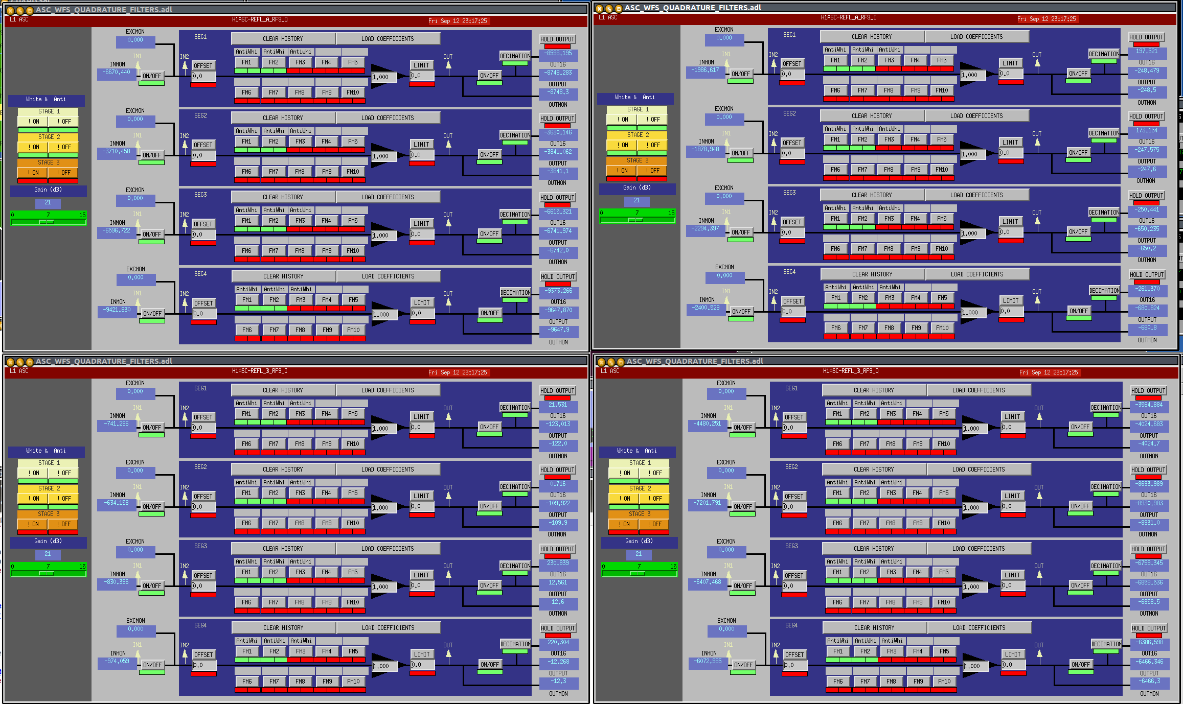
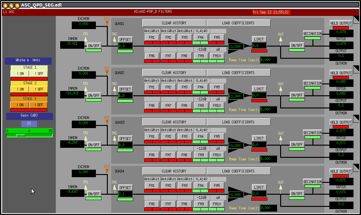
Whitening gain: Changed to 12dB (from 45dB)
After the above adjustment was done, the whitening gain was lowered by 33dB so that the QPDs wouldn't rail when the PRC is locked to the carrier, and dark offsets were remeasured and set. The nominal whitening gain now is 12dB.
"toW" filters in the input are now "uW"
"toW" filters in FM10 of the input are redone such that the output is the power the diode receives in micro Watts when the whitening gain is 0dB, the filter name was changed to "uW", and I put "-12dB" filter in FM9. This way, when you change the whitening gain all you need to do is to change FM9 or add other fixed gains in FM5-8.
Anyway, I used the following calculation:
Responsivity of the diode is 0.8 A/W. Transimpedance is 1 kOhm (https://dcc.ligo.org/LIGO-D1001974). ADC is 2^15 [counts/volt]. There's no factor of 2 (single ended signal V is sent out as +-V differential, but it's converted back to V at the receiving end).
So the entire chain has 0.8A/W * 1 kOhm * 2^15 cts/V = 2.621E7 cts/W = 26.21 cts/uW.
"uW" filter is just a gain of 1/26.21 = 0.038. (FYI, "toW" filter used to have a gain of 0.0056, don't know why.)
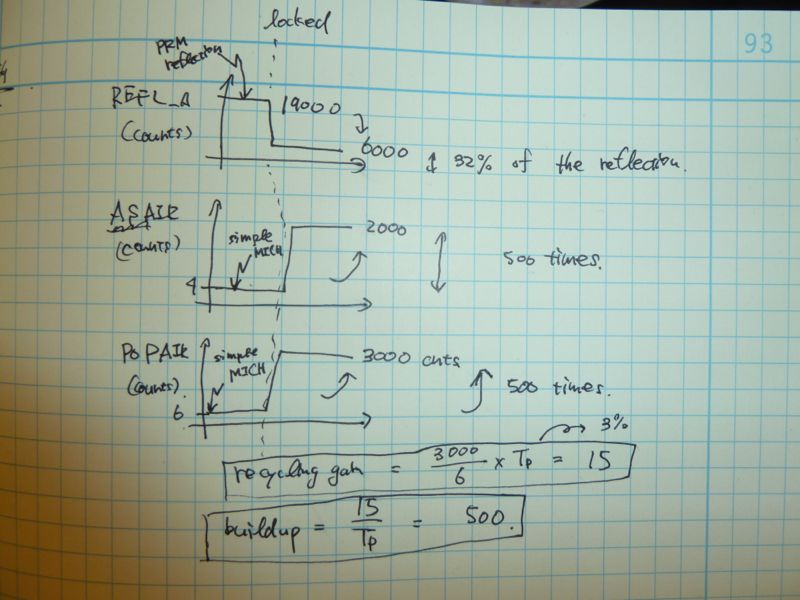
With the straight shot beam, and with "uW" and "-12dB" on while the whitening gain is 12dB, POPA and POPB SUM are 0.34 and 0.31 uW respectively. OTOH 10W(MC)*3%(PRM)*229ppm(PR2)*10%(90:10)*1/2=0.34uW, so it's reasonable.