Lisa, Sheila, Alexa, Nic, Jamie, Kiwamu
We managed to lock the PRMI on the sidebands tonight. We estimated the servo gain settings from the gains in the carrier-locked condition. The lock was stable and lasted for more than 40 min.
Also, we saw an angular drift in pitch of PR3 when the carrier was locked. This behavior was consistently observed.
(Carrier lock)
We intensively worked on the carrier-locked PRMI in the daytime and we could repeatedly lock the PRMI on the carrier. The script which Alexa wrote is now interpreted in a guardian code by Sheila. It uses the variable finesse technique. The code is available but it is still a working progress.
At about 3 pm local, we noticed that the motion in the Michelson was too large for us to keep locking the PRMI. At that time, Fil and Aaron were working around the beer garden, but this may not be a direct cause of the Michelson fluctuation because we did not see a significant improvement after they left. At this particular point, we could not keep closing the Michelson locking loop because of too large angular motion in the Michelson. This large motion gradually disappeared some time later and we could get back to the locking activity in the evening.
(PR3 tends to drfit in pitch)
When we locked the carrier-PRMI, we noticed that the power build-up degraded on a time scale of approximately 10 minutes or so. After some investigation, we identified it to be PR3 which drifted only in pitch by about 0.5 urad. We repeated the same observation a couple of times. PR3 always tends to drift to the negative side in the oplev counts. After a unlock event, it tends to go back to the original angle on a similar time scale. This indicates some kind of thermal issue. In fact, I did not observe a similar effect when the PRMI was locked on the sidebands. Sheila implemented an oplev servo on PR3 to mitigate the issue. In parallel, we should start working on some ASC loops.
Also, the BS oplev showed an approximately 0.5 urad drift once, but this did not seem to correlate with the power degradation. Perhaps this was simply some readout noise or something.
(Carrier lock without the variable finesse technique is difficult)
I still don't understand why this is so difficult, but locking the carrier-PRMI without the variable finesse turned out to be difficult. Since we already knew the right gain settings based on the variable finesse condition, we tried locking the PRMI directly. However, I succeeded in locking it only once. Plus, the lock did not last more than 20 seconds or so. Probably this was because I did not have the power normalizations which make the servo loops less sensitive to the angular fluctuation in the PRMI. This needs further investigations.
According to the variable finesse technique, we estimated the right MICH gain with ASAIR_RF45_Q to be -7, and the PRCL gain to be -0.2 with REFL_A_RF45_I. When I obtained the short lock, the gain settings were -9 and -1 for MICH and PRCL respectively. I used a trigger and triggered filters for both loops. It was around 4:23:56 in UTC.
(Sideband lock)
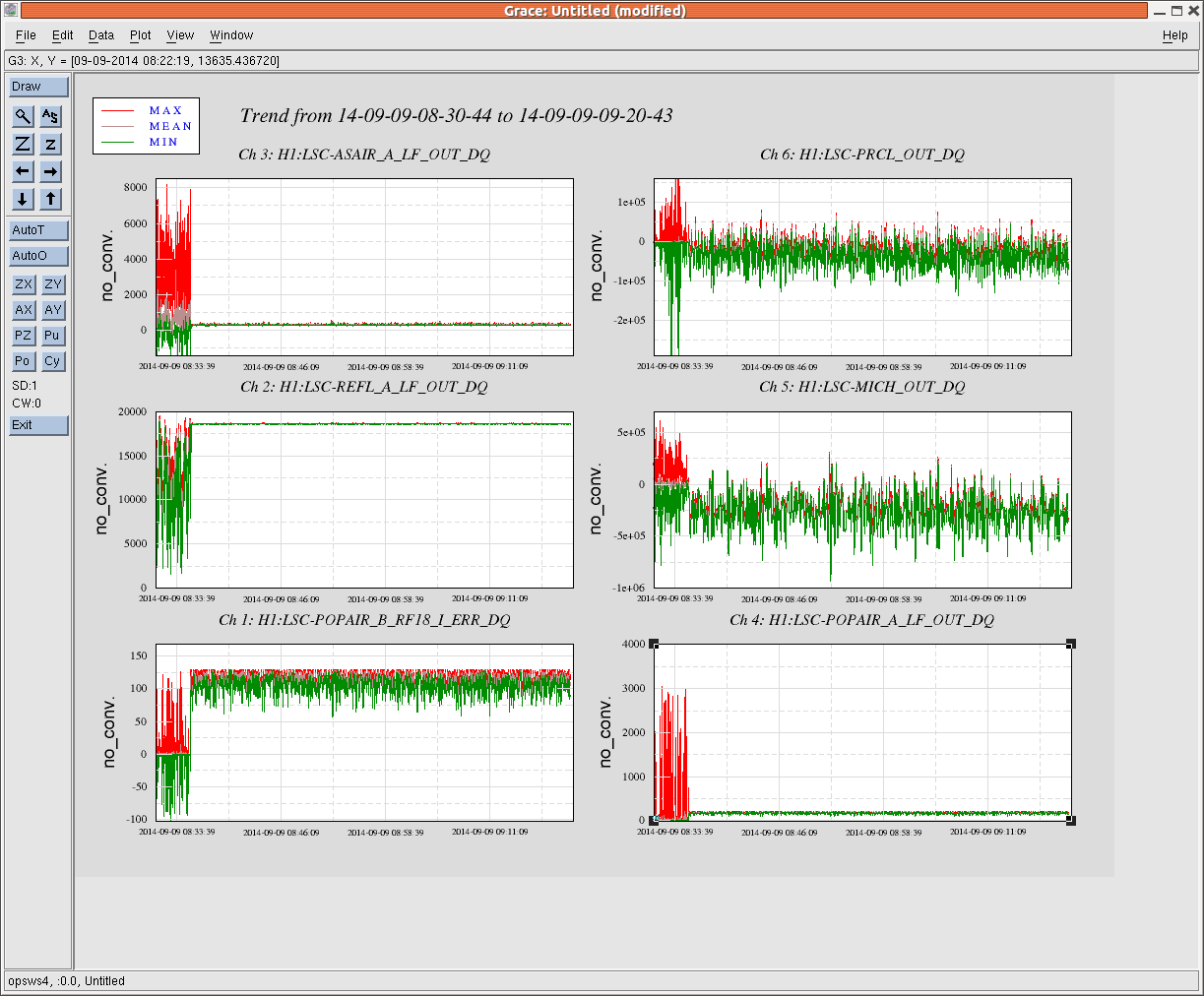
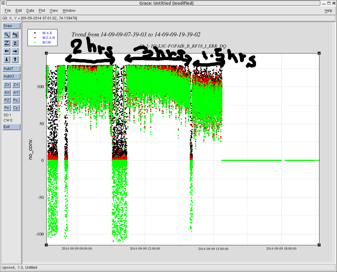
We then moved onto locking of the sideband-resonant PRMI. I simply flipped the sign of the PRCL loop to do this. But, this did not work -- I did not get a short lock. So I suspected some kind of cross-coupling in the sensing matrix and started trying to the other REFL sensor, REFL_A_RF9, which should be less sensitive to the Michelson motion. I measured the difference in the readout gain of the RF9_I and RF45_I by locking the carrier. The RF9 was smaller by 13 dB than the RF45. Taking this into account I tried some gain settings in MICH and PRCL while keep using ASAIR_A_RF45_Q for the MICH control. I attach a trend of some signals below to show the PRMI had been locked for a while, more than 40 min. Note that I did not have to re-align an optic to maintain the lock. I did not see drift in PR3 in this configuration.
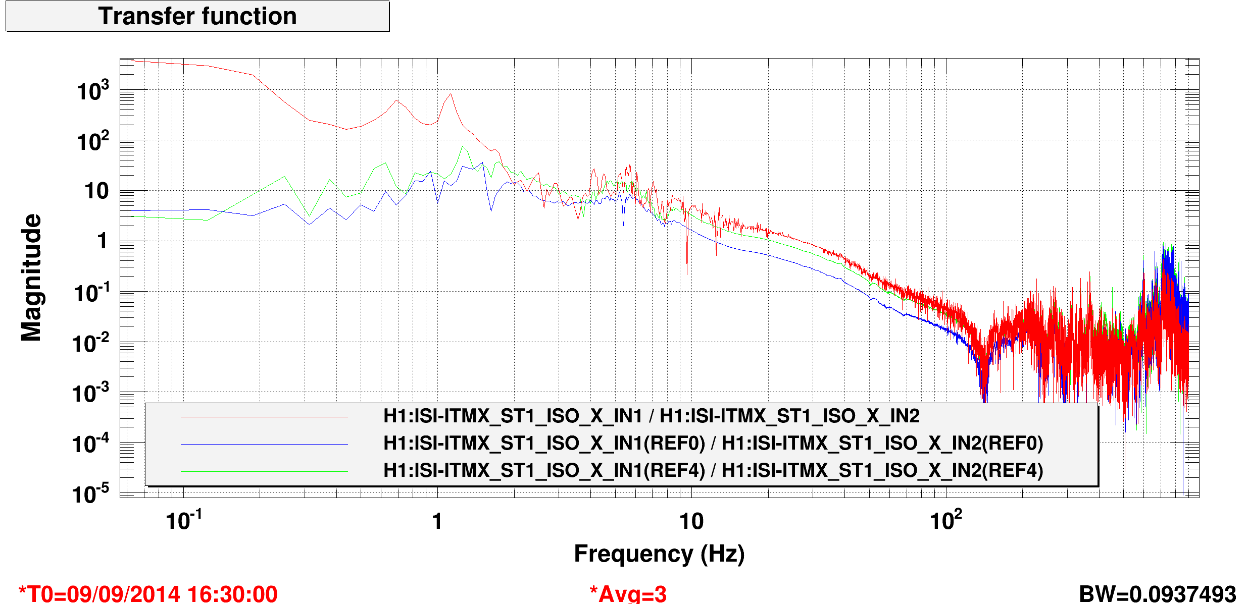
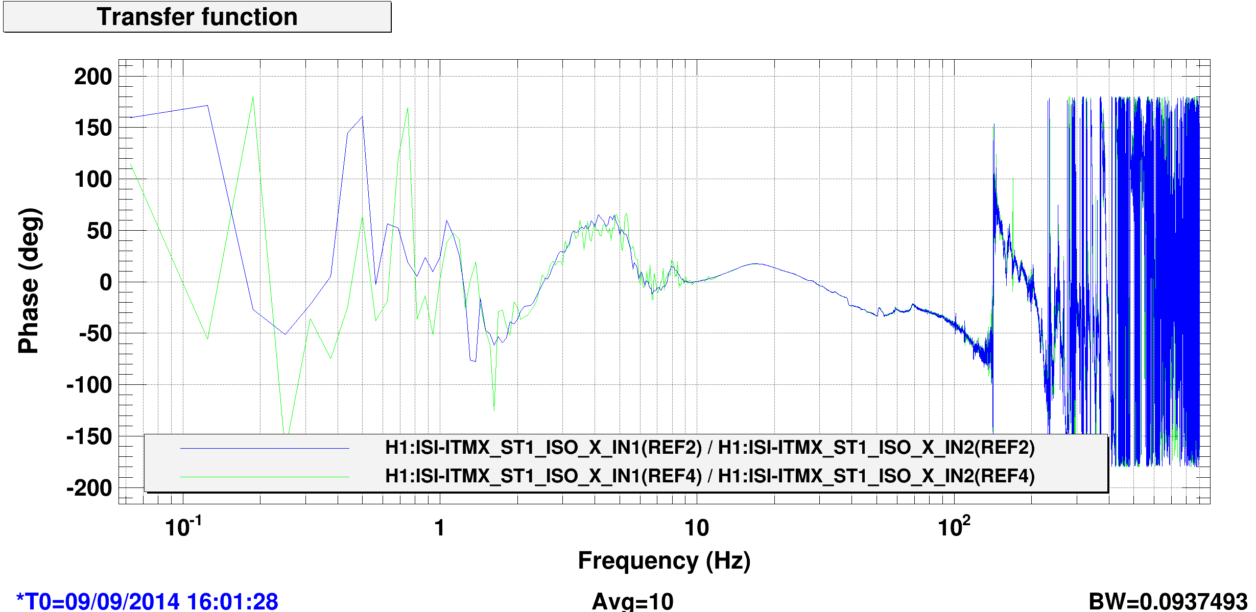
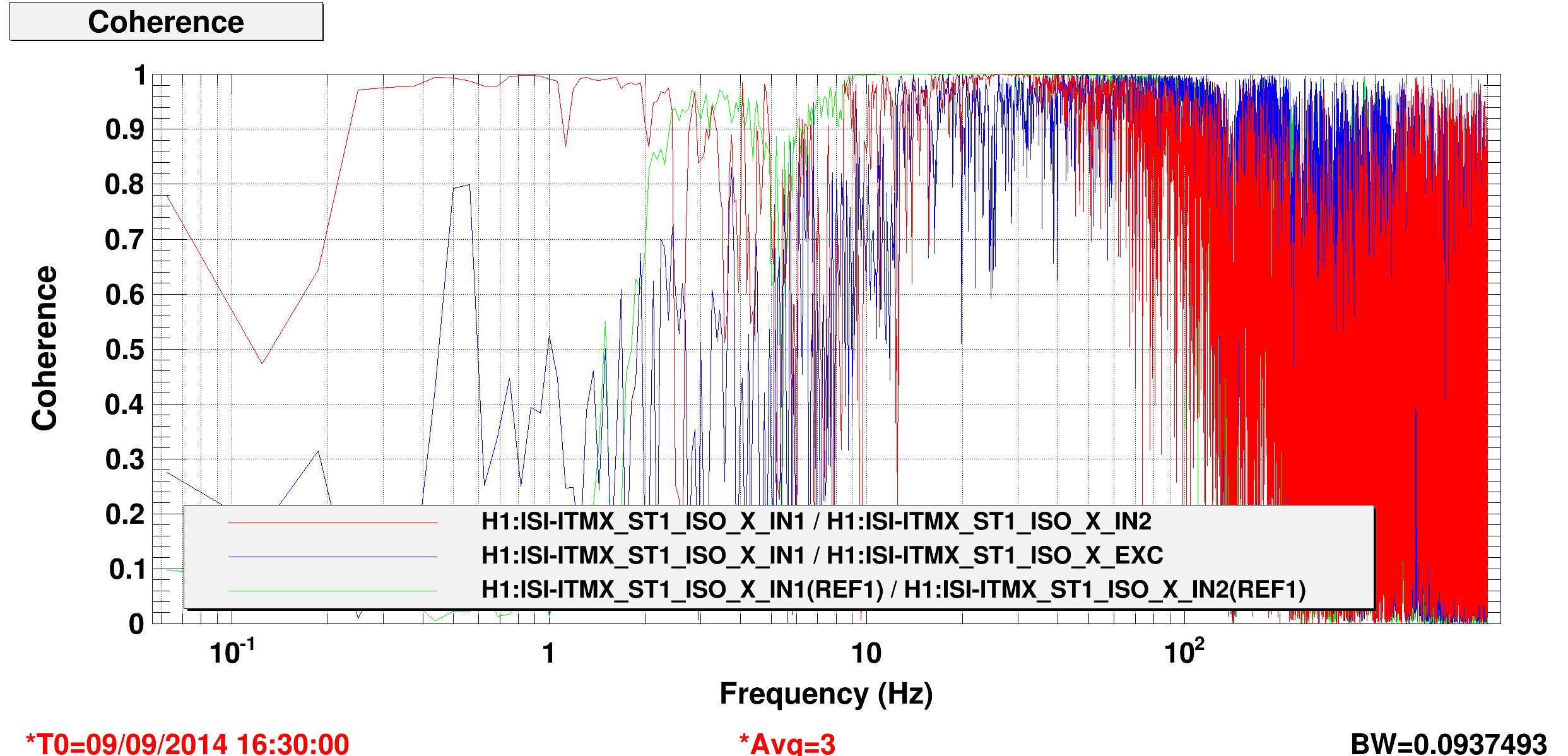
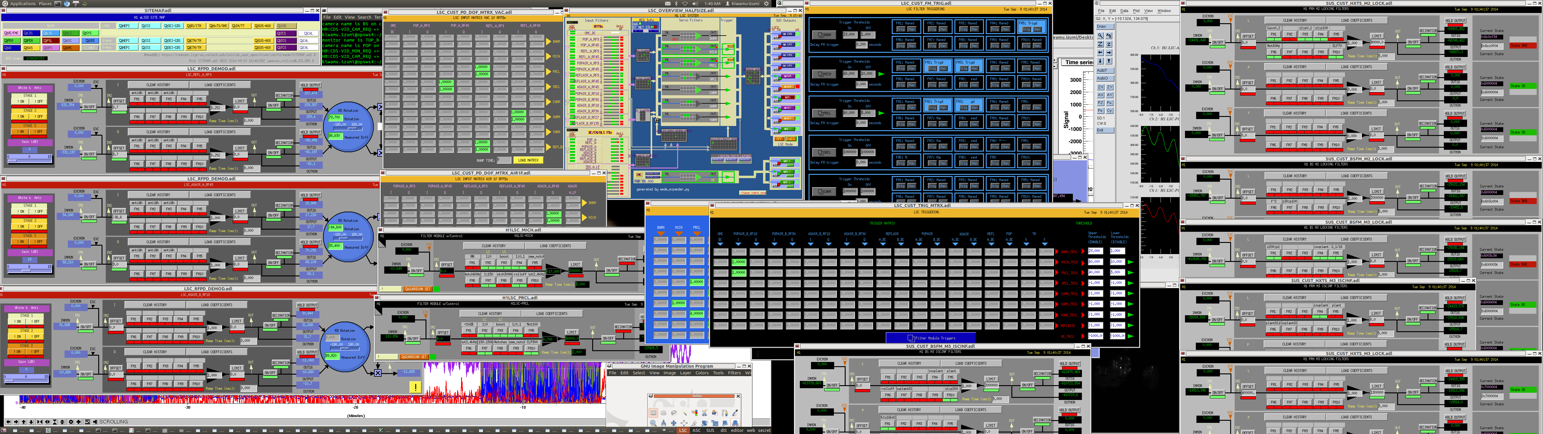
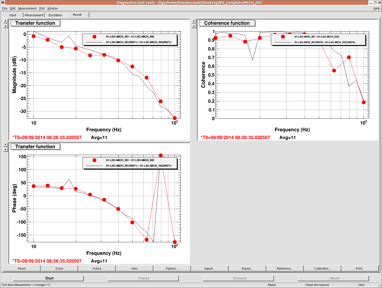
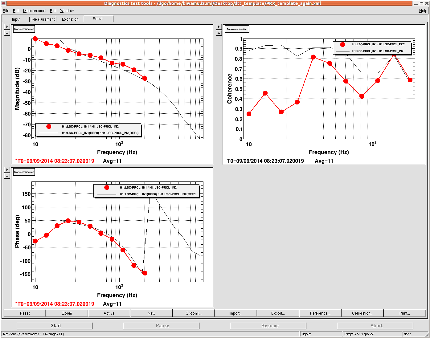
The first acquisition was made with a MICH gain of -10 and PRCL gain of 0.7. These numbers are not far from the expected. Once it started locking, I tuned up the alignment, demodulation phases, UGFs and locking thresholds. I attach a screenshot of the whole settings, MICH and PRCL open loop transfer functions.
It seems that lock acquisition is smoother with a slightly lower gain in MICH. For example, I kept using a MICH gain of about -7 for locking and increased it to the nominal gain of -17 once it was locked.


Alastair, Jim, Aaron, Filiburto, Dave
Alastair later found that the new DAC card was not functioning correctly. We found that channel 12 was outputting 24V instead of 8.4V. We tried swapping out ribbon cable and interface cards, but eventually put the original DAC-on-carrier-card back in to get TCS back on track for this evening. We will investigate further later in the week.