arnaud.pele@LIGO.ORG - posted 19:12, Tuesday 29 July 2014 (13056)
IMs tfs running overnight on opsws1
Attached are damped/undamped spectra of osem signals of HAM3 suspensions (PR2 MC2). No particular concerns
Matlab TFs are set to run at the X end station overnight as follows:-

- TMSX (TMTS) M1-M1 undamped TFs

Starting now, and when complete the measurement status will revert to OFF and damping loops will be restored to the ON state.

These measurements have been initiated from the opsws2 workstation.
WP4758. Rolf, Jim and Dave.
We upgraded the following models to branch2.9: h1iopsusauxey, h1susauxey and h1iopsusauxex.
After h1iopsusauxey was upgraded, I did see the ADC error bit in the STATEWORD get set three times in the first 30 minutes. The enhanced ADC diagnostics Rolf put into the /proc status file showed the ADC0 READTIME MAX did exceed the 17uS limit (went to 18 each time). Unfortunately no addition errors were seen for the next 3 hours. We tried the same test on IOP EX, but that did not exhibit the error at all.
So it seems the ADC error is in 2.9 at EY, but is very intermittent.
I reverted both IOP and user models on h1susaux[ex,ey] back to RCG2.8.4 and concluded the test.
nm
During close-out work on the ETMX chamber, and while waiting for particle counts to drop, I took power spectra up to 50 Hz for both ETMX (QUAD) and TMSX (TMTS) suspensions (n.b. suspensions were still locked).

I observed a higher noise floor, of almost an order of magnitude, for the ETMX L2 (PUM) UL sensor channel (see ETMX_Original.png below).

To help determine if the source of the excess noise resides in-chamber or with the electronics chain I swapped the ETMX L1 and L2 stage in-air field cables at the Satellite Box (H1:SUS_ETMX-17 and H1:SUS_ETMX-17) and re-took the power spectra (see ETMX_Swapped.png below). It can be seen that the excess noise now moves from the L2 stage to L1, thus indicating that the source of the excess noise is down-stream i.e. with the field-cables or in-chamber.

Ideally, the above test should be repeated at on the air side on the vacuum feed-through to eliminate the field cable. However, most likely, this is an in-chamber AOSEM cabling/connector issue.
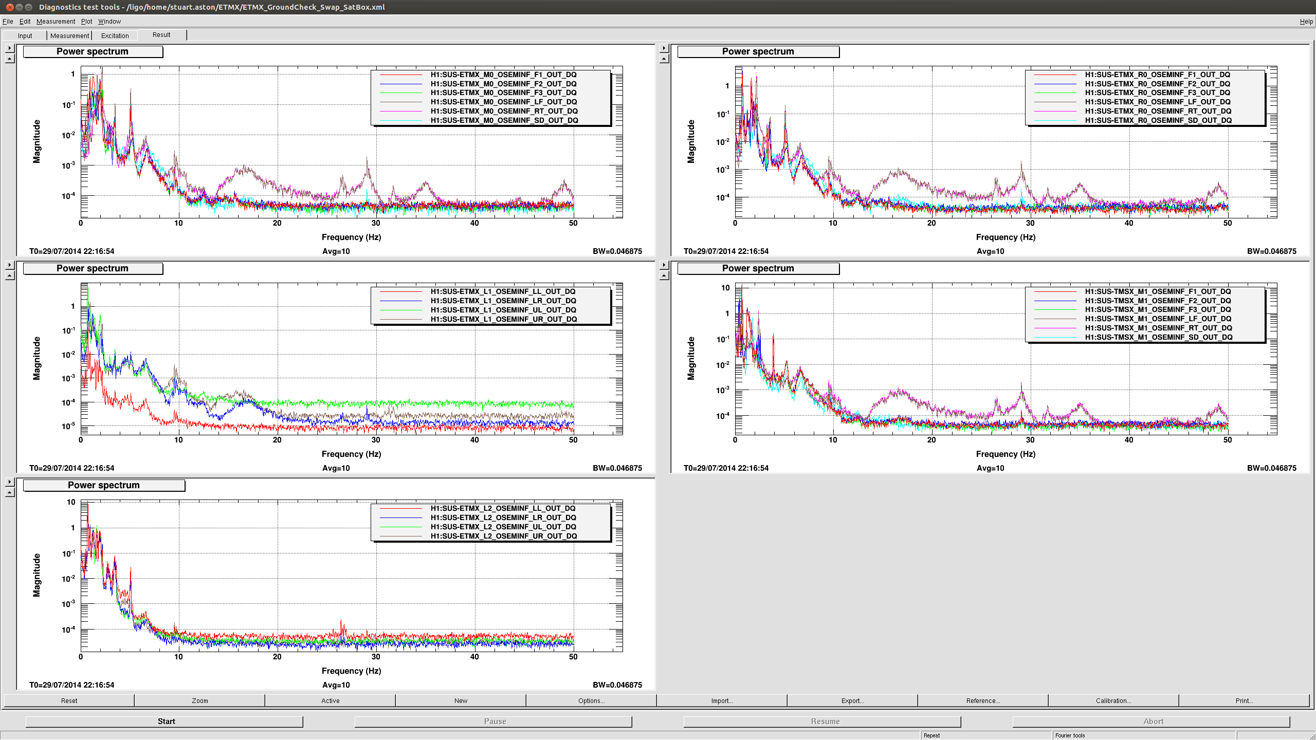
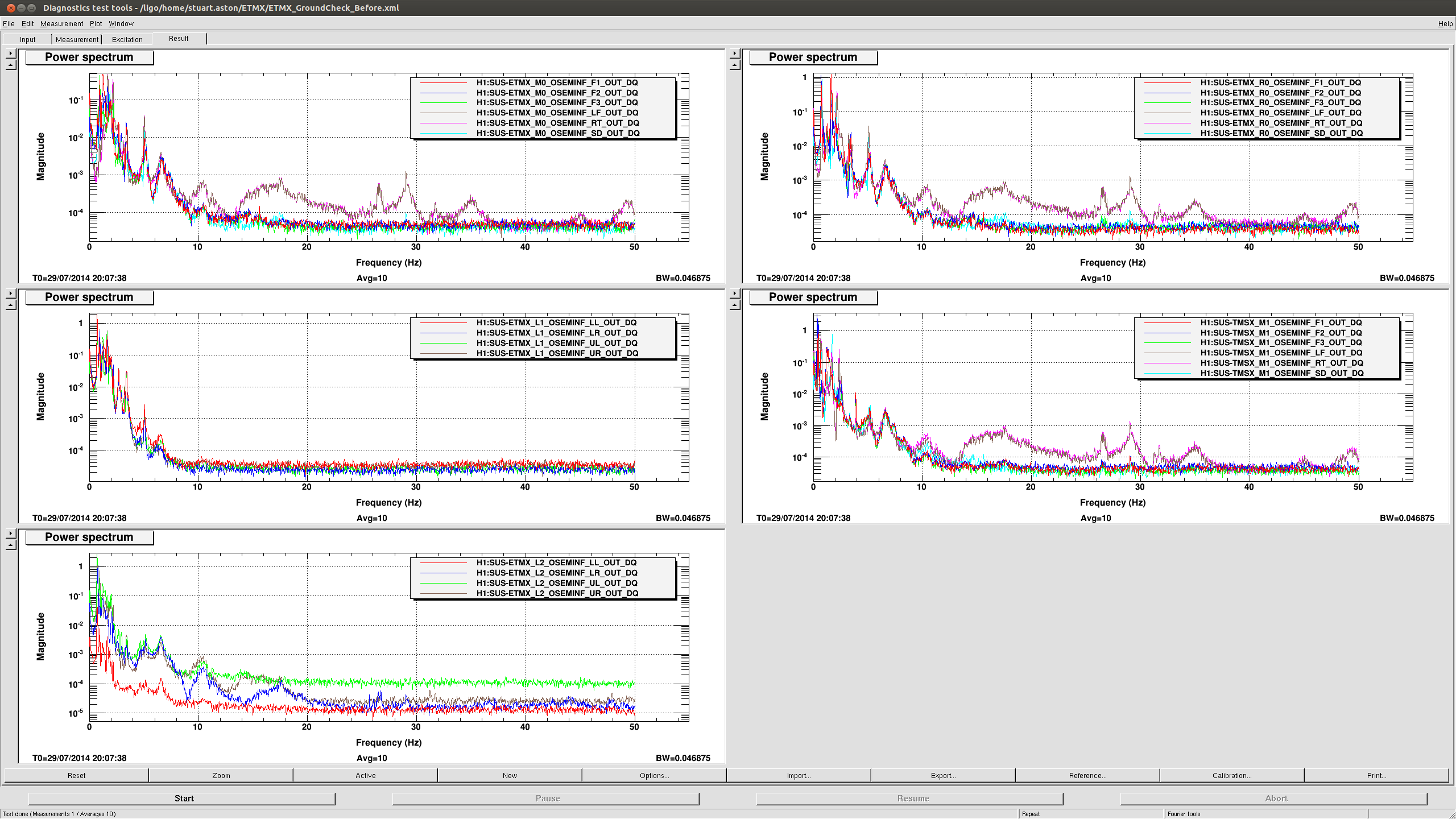
Searching through acceptance measurements that were taken for ETMX, it would appear that the excess noise exhibited by the L2 UL channel has previously been reported, and is therefore not a 'new' development since opening the chamber (see LHO aLOG entry 9608).
Sometime between the SUS and ISI payloading mid-week last week the alignment of the ITMy QUAD wandered off. The ACB install and alignment proceeded late last week. On Monday (yesterday) we resumed realignment of the ITMy SUS. This involved the usual many day effort of realigning all 3 stages of sensors during the test mass and CP pointing alignment. By COB on Monday we had good sensor alignment and good IAS pointing, however we had a strange 2.6Hz peek on V and P DOF TFs. Overnight TFs confirmed these peeks. Today, we have again spent all day trying to understand and mitigate crosscoupling of this peek via shifting the sensor mounting box around and realigning the OSEMs each time. No help.
WED
SUS and ISI Payloaded
Good IAS alignment, Good sensor alignment, Main Chain rubbing
THUR/FRI
ACB Install and alignment
Closed the ring heater.
MON
Main chain rubbing had been alleviated, IAS and sensor pointing ongoing
2.6Hz in some DOF TFs of M0 and R0
TUES AM
Sensor mounting table cloth realigned in an attempt to improve sensor centering along x - pushed towards main chain, all BOSEMs realigned.
Major L1 and L2 OSEM alignment coupled with both chain pointing alignments.
Checked a few flags that possibly were crooked. None found bad.
No problems with cables, EQ stops or flags found between chains.
2.6Hz peek found to have moved to 2.4Hz.
TUES AFTERNOON
Sensor mounting table cloth realigned in an attempt to change any coupling seen by the sensors to mis-pitched/mis-yawed/mis-rolled top mass flags. All 12 top BOSEMs realigned.
Tweeked slightly miscentered L1 Upper and Left BOSEM centering.
No problems with cables, EQ stops or flags found between chains.
Opened the ring heater (grasping at straws).
2.4Hz still there on both main and reaction.
TUES LATE PM
Locked ACB with 1 bracket in an attempt to stop what we observed to be a 2-3Hz bounce resonance.
Story TBC...
I attached tfs of top mass main and reaction chain undamped itmy showing the difference with ACB LOCKED/UNLOCKED. Suprisingly it does change the response, and the resonance at ~2.42Hz disappears when the ACB is locked.
Full tfs will be ran tonight, on the main and reaction chain of ITMY, in order to confirm that extra resonances seen this morning in the tfs ran yesterday night are independant of the suspension.

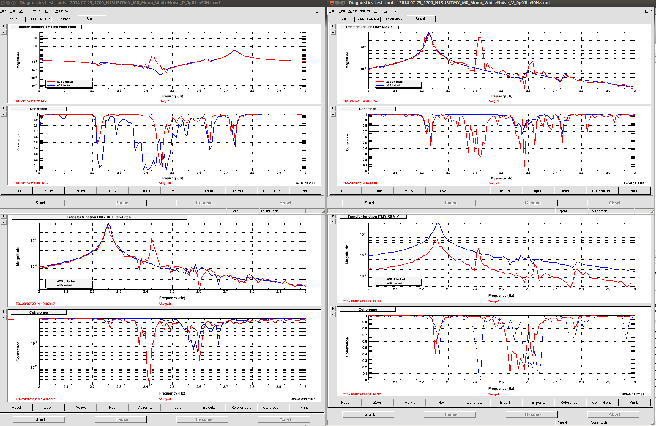
A. Pele, J. Kissel, B. Weaver, T. Sadecki

Confused as to why the ITMY dynamics are affected by the ACB dynamics, we postulated that it's because the ISI is locked, with HEPI floating -- directly shorting ST0 (from which the ACB is suspended) to ST2 (from which the QUAD is suspended).

While Betsy & Travis were on their way out to center the R0 OSEMs (not mentioned above, but the original reason for their TUES LATE PM into-chamber), Arnaud quickly grabbed an ISI Damped vs. Undamped comparison on M0 Pitch because he was on a roll with "it's the ISI's fault" (See LHO aLOG 12945 and 7625). We even bet bacon-wrapped jalapenos on it.

ISI damped vs. undamped made the spurious feature disappear -- see first attachment. Given that the ISI is locked, turning on the damping loops should have made no difference. Because it *did*, perhaps the ISI isn't locked "well"? Unfortunately, we didn't get enough data points to make a convincing argument before Betsy and & Travis locked up the ACB ... AND, as Arnaud didn't mention above, all of his comparisons are made with ISI *undamped*, and we see no feature. (Note "damped" means both ST1 and ST2 are damping loops were turned on. HEPI is floating, and isolated under "pos" blend filters in both scenarios.)

Totally baffled (pun intended) by this ISI damped vs. undamped improvement, I grabbed some data from ITMX, which -- if the theory holds -- we should see some resonant features appear and disappear with damping, because the ISI is free. I see no such features; see second and third attachment.

So apparently, as has been the case for lots of suspensions on this last install push, we're in some weird new state where the ISI is mostly-locked but free enough to be affected by damping loops HEPI. #sevenstageisolationsystem

HOWEVER -- the message: we've turned two knobs ("ISI damped vs. undamped" and "ACB unlocked vs. locked"), semi-simultaneously, both seem to get rid of the resonance in the SUS dynamics -- implying that the problem is not QUAD related. As Arnaud says above -- we'll confirm with the results from tonight's full set, but if they're clean I vote we move on with the remaining install activities for this chamber ('cause we'll have more configurations, and more measurements to ponder).
Note, particle counts before we started work for the day in BSC1 yesterday (the day of the above post) was:
0.3um 10
0.5um 0
1.0um 0
Then the PC ran out of batteries so we didn't take any more counts. WIll try to be more dilligent today.
Data collection expected to last 48-72 hrs during which time the pressure will increase in the X1 BT module -> Expect gauges PT134B, PT144B, PT343B and PT344B to exceed alarm levels -> No action required for these four gauge alarms during this test period
Gary T, Danny S, Matt H, Stuart A
Well was a frustrating day today. We removed the 3 wafers (2 horizontal and 1 vertical) and the vertical optic that was still in chamber, and also put in a 1inch optic (still with its first contact). We gave everything a wipe and then vacuumed everything then wiped again.
Keita asked us to centre the BOSEMs on the TMS with the offsets applied and the TMS damped. And so this is what was done. Keita had a look at what we had done and okayed it.
Counts were still really high after vacuuming so we broke for lunch and during that time we got Jim to unlock the ISI. We wiped again and counts okay, so thought we could start the closing process and started with blowing off quickly the TMS. This put the counts up highish, but figured we would try blowing between the two optics for the 5 minutes agreed upon with Mike L and Norna, let counts settle low and then pull FC. Unfortunately we could never get the counts to go lower than say 400-500 (for 0.3um) with people not moving in the chamber for ~30 mins, and as soon as they did the counts would go up into the 900's-1300's (for 0.3um). We tried wiping floor yet again and couldnt get counts lower. Note: we even have a new BSC door cover on.
So I talked to Calum and we decided that we will just have to go with as low as counts as we can get and just log the counts we have whilst doing the closeout tasks. As its getting on today we decided to stop here, Jeff B is going to come in early and wipe the chamber again one more time...this should give time for everything to settle and then we wil ljsut go for broke with pulling this. I dont think we can get this much better in the near term. I think shows how important that we need to do cleaning on the go everytime anyone is in there.. We are very confident we can get everything done in a couple hours after morning meeting tomorrow though and then that end is done.
PS..Gerado just came and talked ot me and the "stuff" we see on the middle viewport of eastern door is on the middle. We we will paint FC on that tomorrow as well and pull that (before we pull FC on optics)
Quick timeline
Particle counts
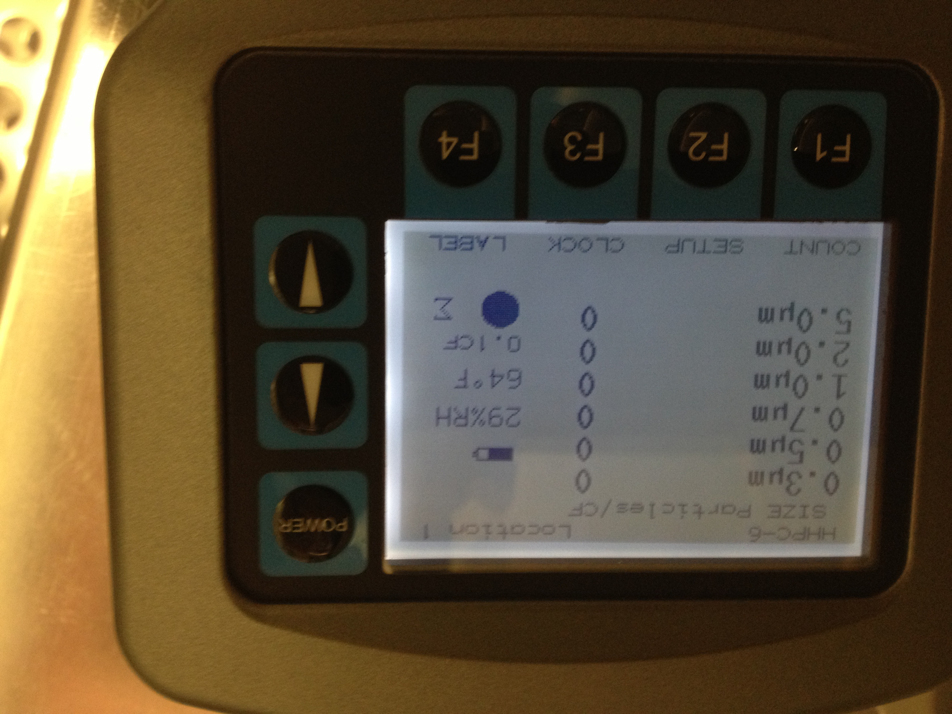
In cleanroom start of day
All counts zero (see pic 1)
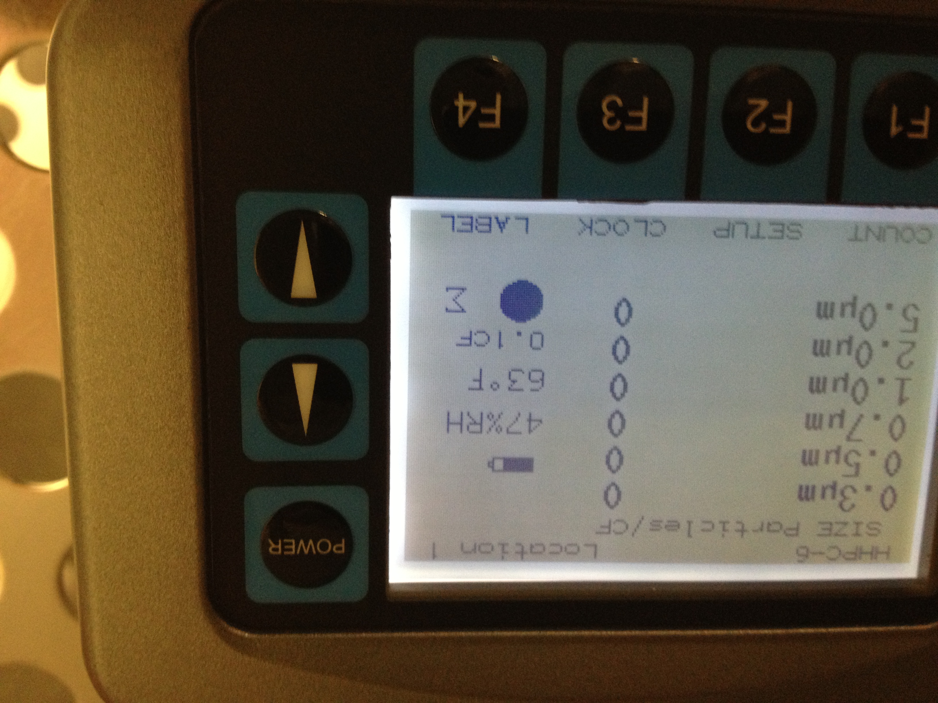
In chamber start of day
All counts zero (see pic2)
In chamber as removing wafers (see pic 3)
0.3um.....950 counts
0.5um....400 counts
0.7um....270 counts
1.0um....200 counts
2.0um..140 counts
5.0um...60 counts
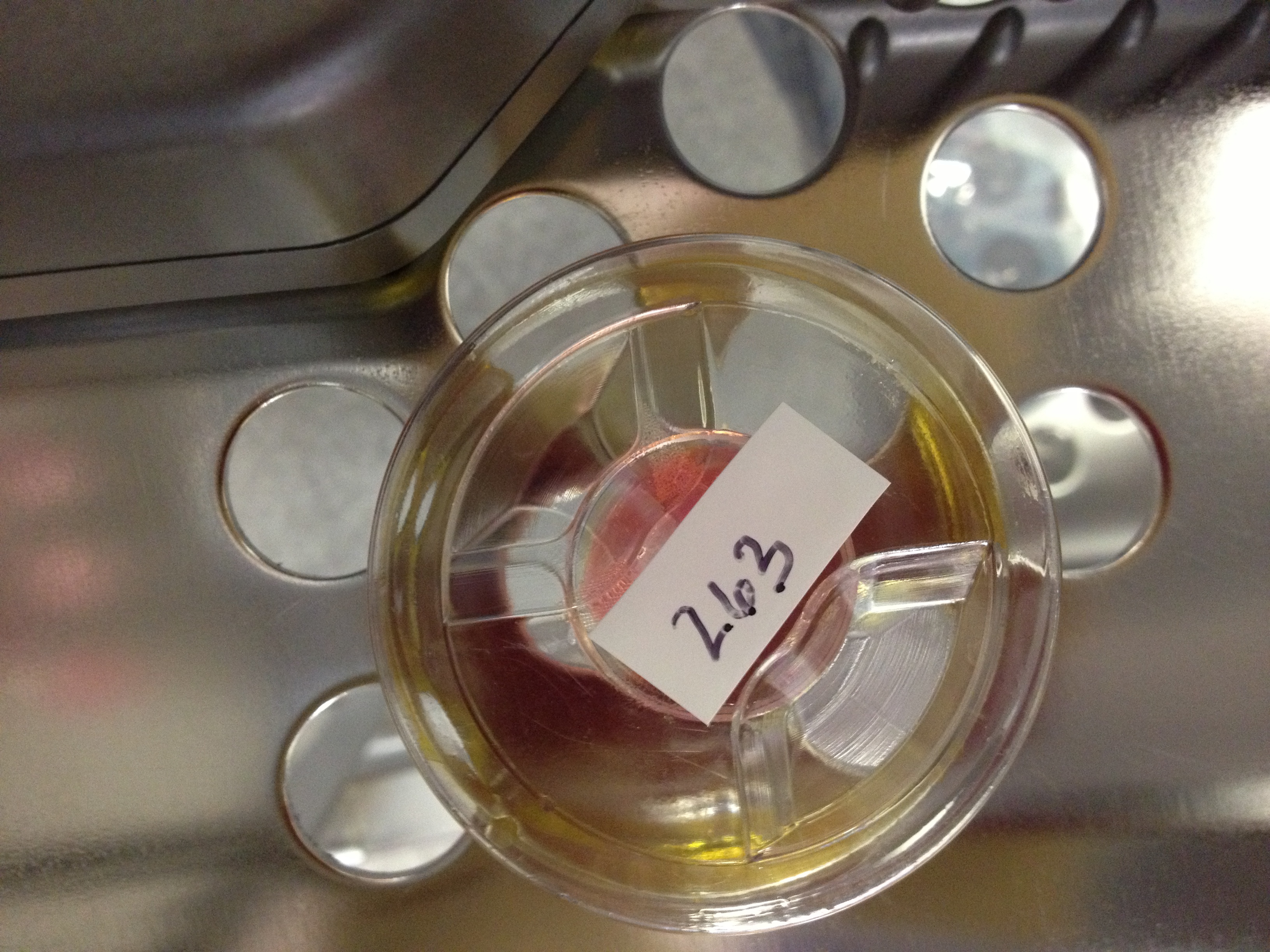
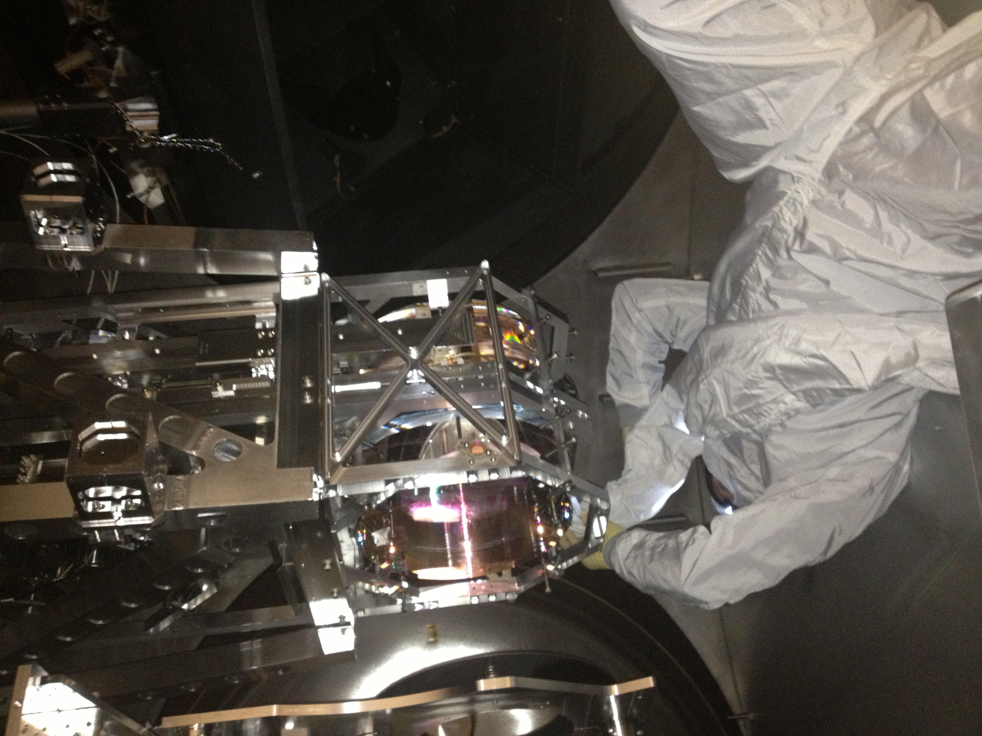
Pic 4....S/N of the optic put into X end station
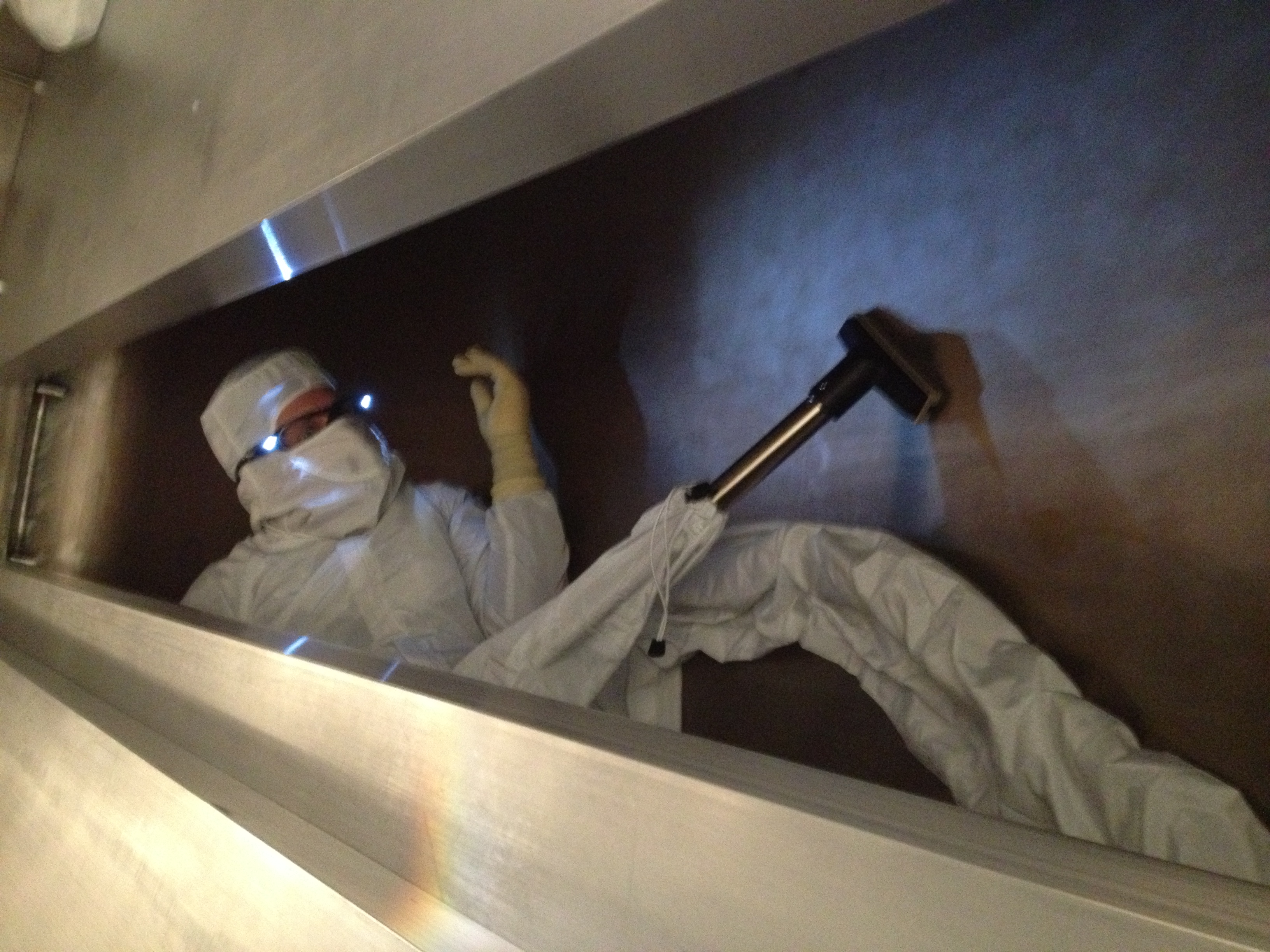
Pic 5...vacuuming under the floor boards
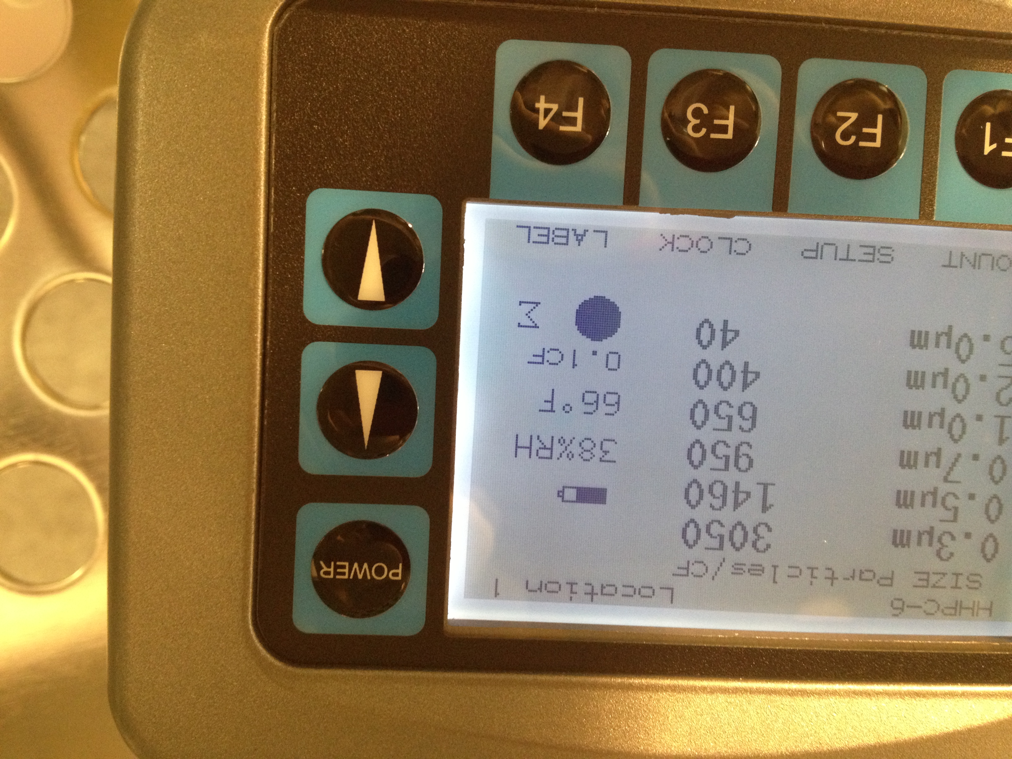
In chamber during vacuuming (see pic 6)
0.3um....3050 counts
0.5um....1460 counts
0.7um...950 counts
1.0um....650 counts
2.0 um...400 counts
5.0 um....40 counts
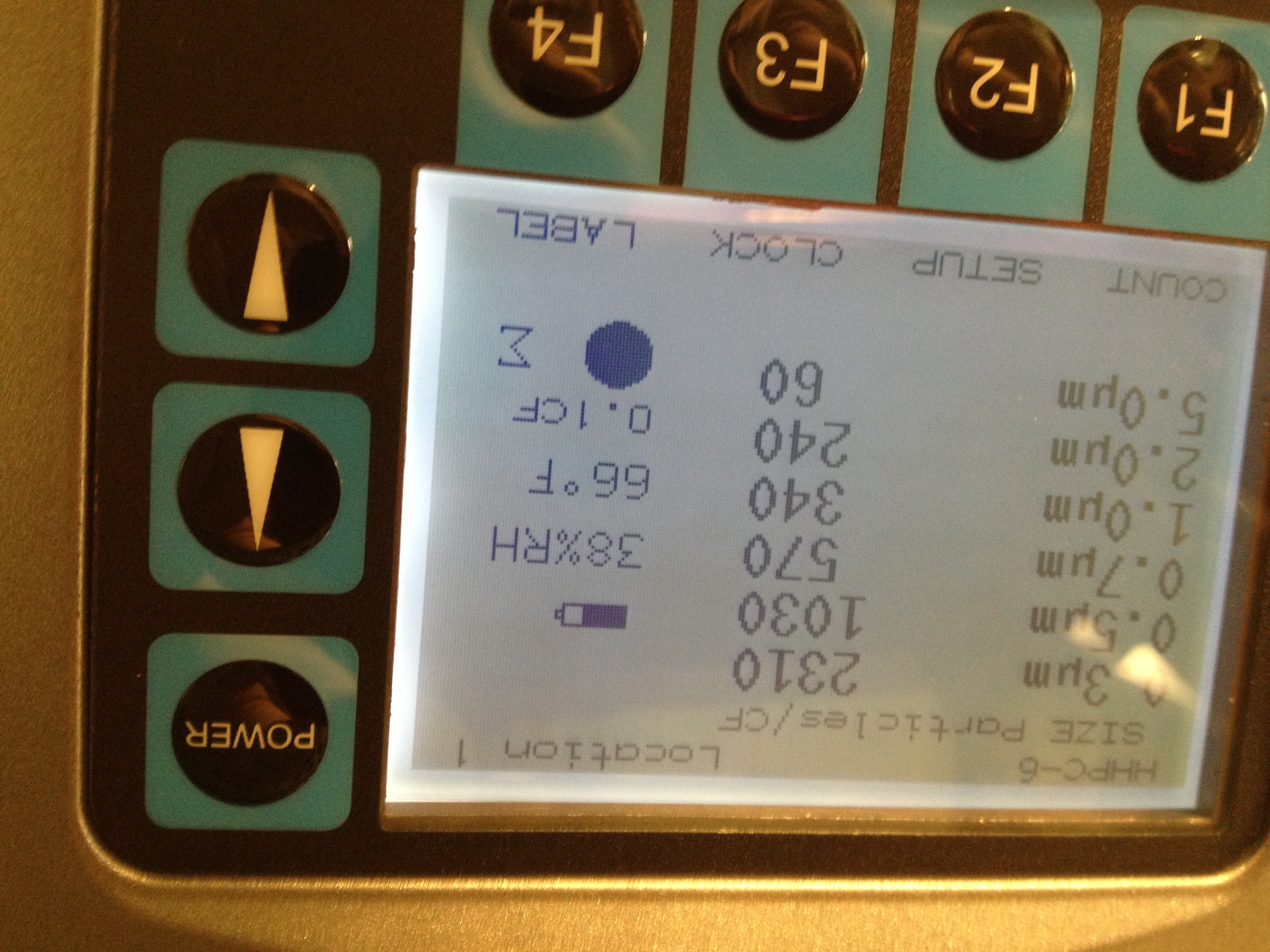
In chamber exiting for lunch..to let counts settle (see pic 7)
0.3um....2310 counts
0.5um...1030 counts
0.7um....570 counts
1.0um...340 cunts
2.0um...240 counts
5.0um....60 counts
1.30pm...in cleanroom after lunch
All counts zero
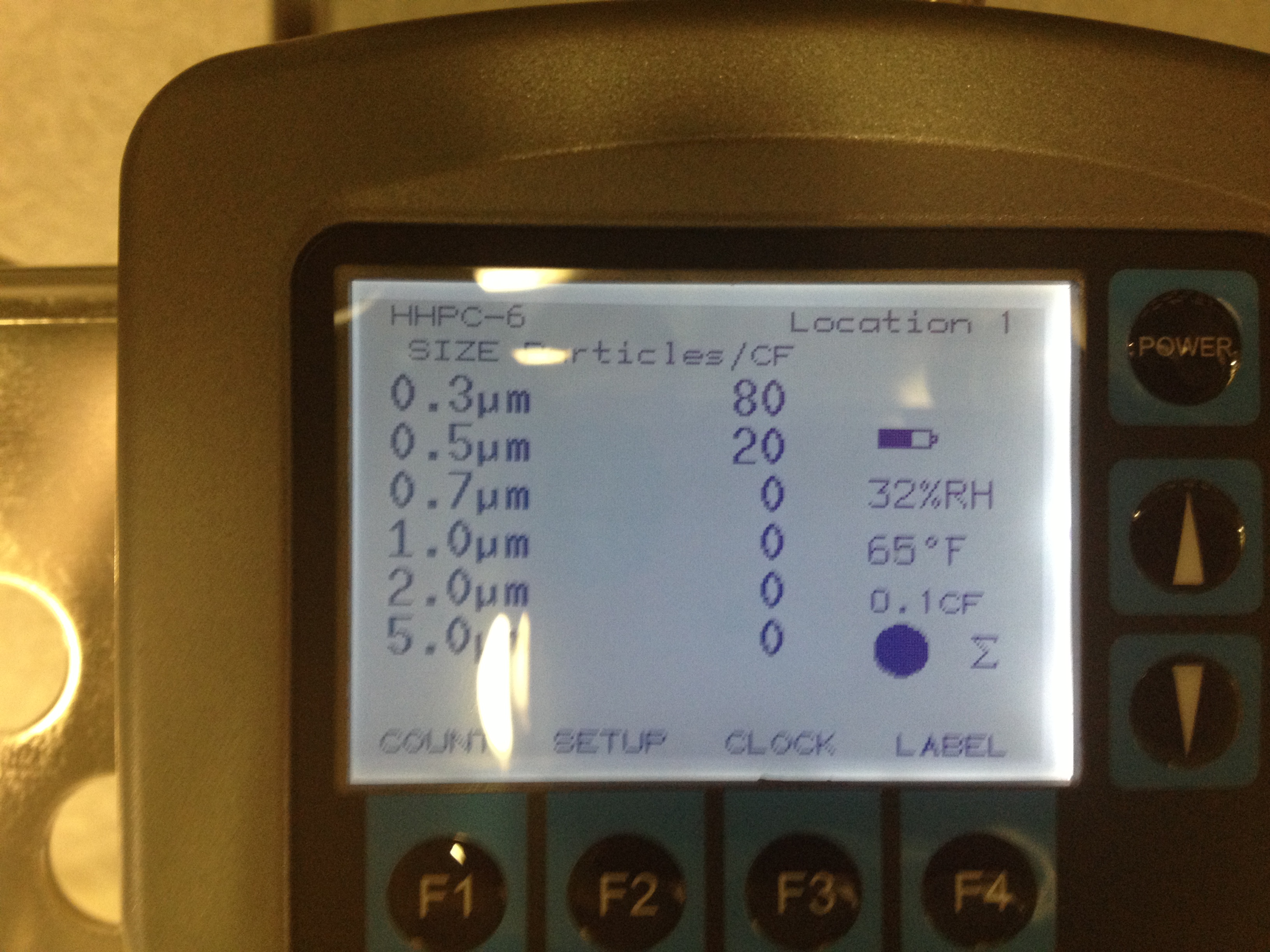
1.32pm..In chamber after lunch (see pic8)
0.3um...80 counts
0.5um...20 counts
rest zero
1:44pm..blowing TMS optics
1:49pm..finished blowing TMSoptics
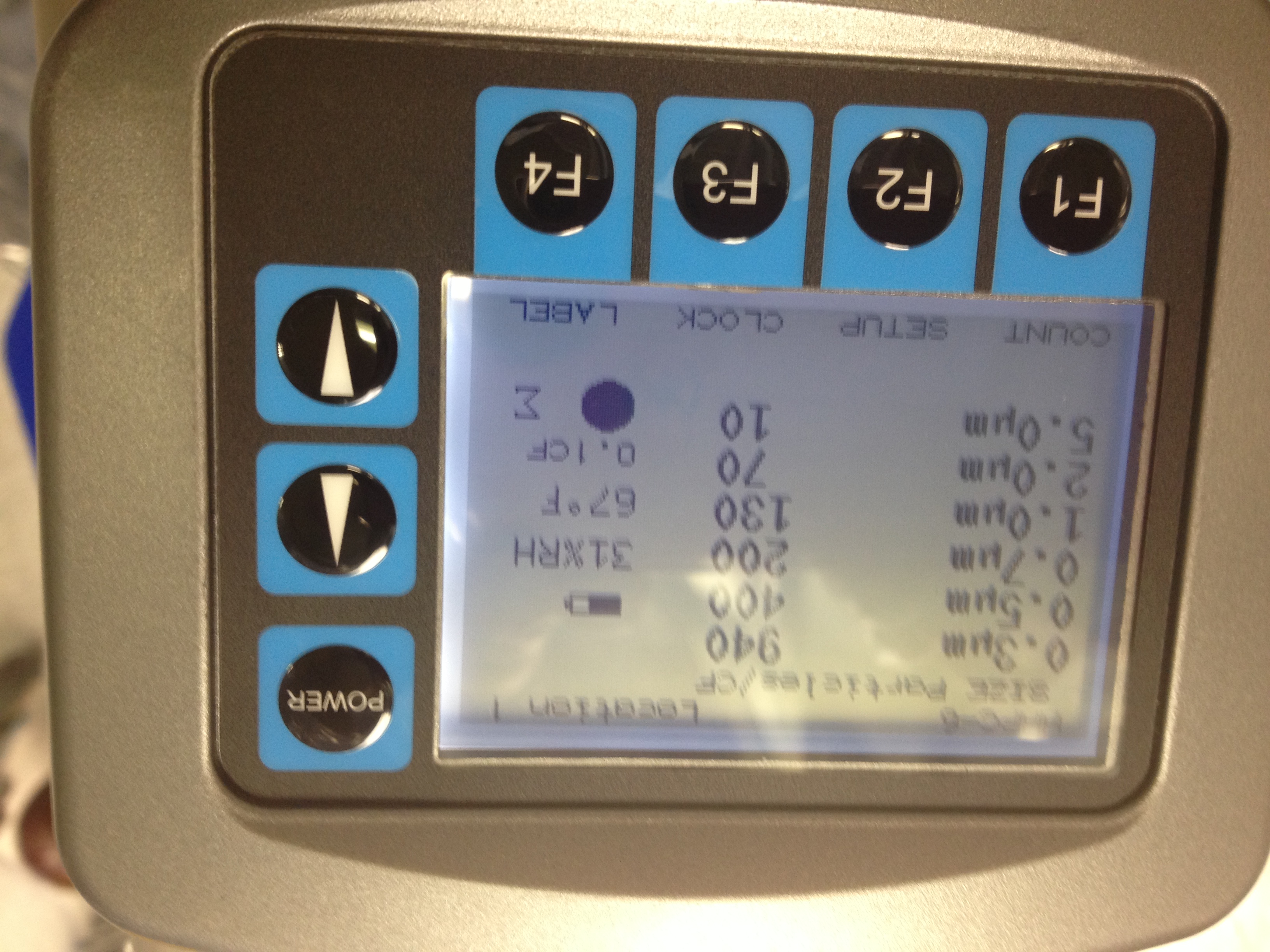
Particle counts (see pic 9)
0.3um...940 counts
0.5um...400 counts
0.7um...200 counts
1.0um...130 counts
2.0um...70 counts
5.0um..10 counts
1:50pm...blowing between two optics for 5 mins
Pic 10...Gary blowing between optics
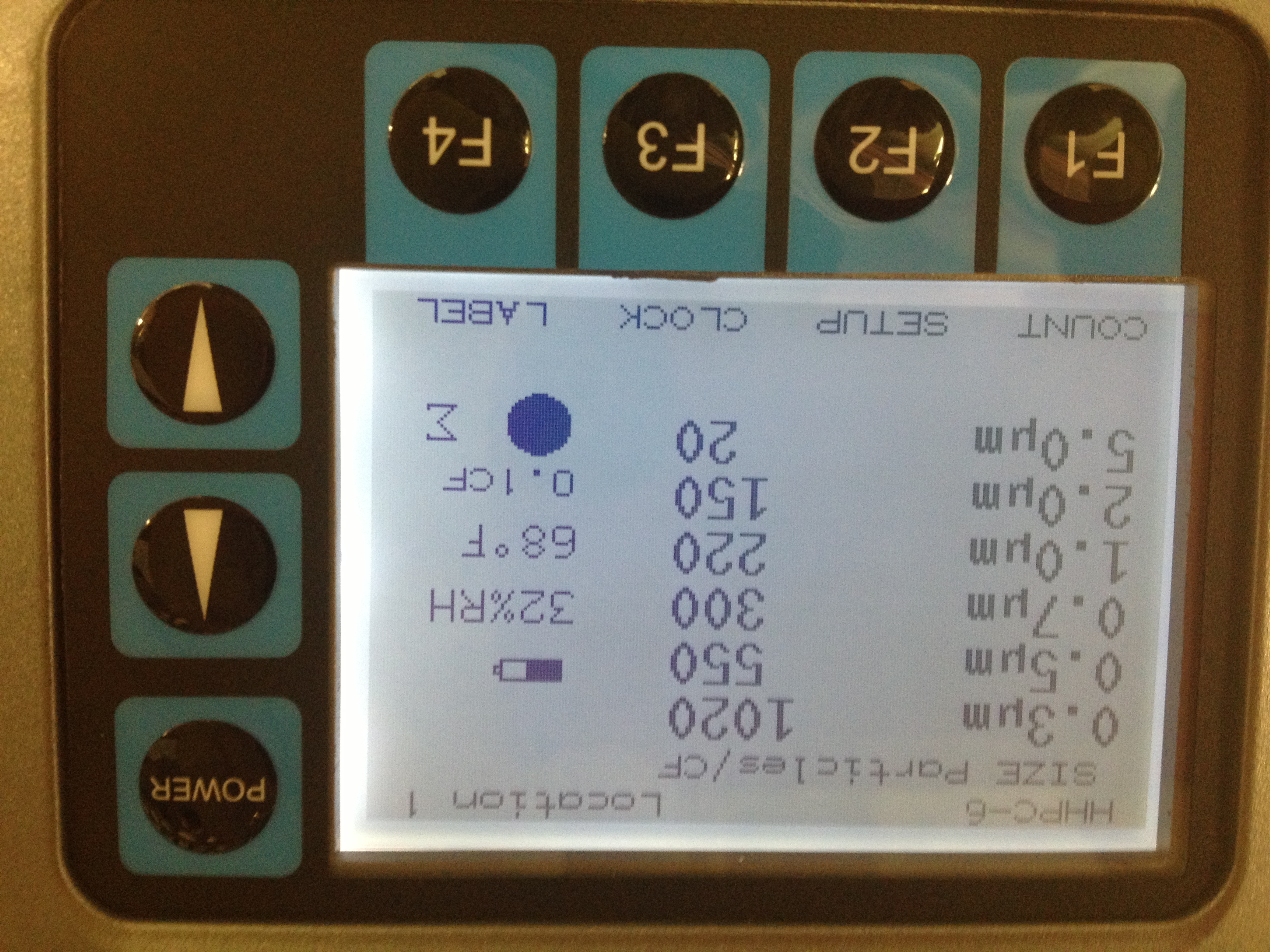
Particle counts end of blowing (see pic 11)
0.3um....1020 counts
0.5um...550 counts
0.7um...300 counts
1.0um...220 counts
2.0um....150 counts
5.0 um...20 counts
1.58pm...starting TMS TF;s
2.15pm..counts still in 400-500's for 0,3um range
2.40pm...talked to Calum about Particle counts....Will go with lowest we have seen (400-500 count range) to be our new "zero" for this chamber this time
2.45pm...counts in 0.3um range back to 600-800 range with little to no movement by guys in chamber
2.52pm..wiping floor again
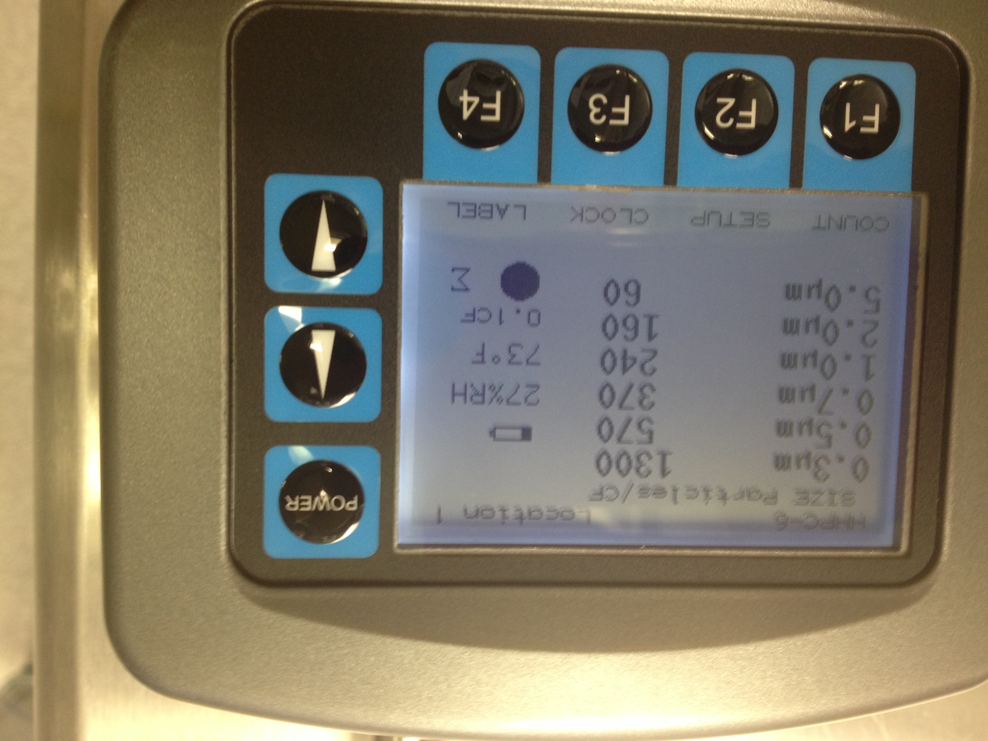
3.17pm particle counts (see pic 12)
0.3um...1300 counts
0.5um....570 counts
0.7um...370 counts
1.0um..240 counts
2.0um...160 counts
5.0um...60 counts
3.30pm..calling it quits

I've mentioned this numerous times, but unfortunately our schedule does not allow for it: The settle time of 0.3-1um dust in chamber is 2-3 hours (see the dust log Justin made a year ago ish). So, what we likely need to do is clean the floor, let it settle 2-3 hours (no traffic), clean the floor, let it settle 2-3 hours (no traffic), repeating the settle and clean steps ~4 times to actually remove the continually stirred up dust. Waiting 30 mins likely will not yield an large improvements in counts unless we can control where it goes.
We have some other experience indicating that this wipe and wait technique works. When we start up a new cleanroom, we often have dirty mops for the first few days as we clean the room and floors numerous times after long settle periods. On the ~5 day, the mops start to look cleaner.
I cannot dispute the 2 hour settling time that you have observed for the LHO BSC's, but all I can say is what I have found and that is that for the closeout of the HAMs here at LHO the last couple weeks (and at LLO before that), I found that the counts would settle on the order of minutes to 10's of minutes if they were high due to something being stired up (ie after people stopped working in the BSC's) ...however i dont recall counts in the thousands in the HAMs, (I also did not find that if someone was working in a HAM chamber that you would see an effect of this work in an adjacent HAM chamber..eg when Hugh working in HAM2 balancing we saw no effect of this when we were in HAM3...similarly with work in HAMs 4 and 5 at the same time). Also I dont recall at LLO it taking 2 hours for counts to settle in the BSC's...but then again I dont recall counts in the thousands either at LLO (maybe it was, I just dont recall it). We (as in the LIGO community) are much more observant now about particle counts and monitoring/logging when work is occurring(if wanted I could try to troll back through LLO alogs to see what numbers we ever saw if/when we reported them). I have been told by various people at LHO today though that this is the "dirtiest" chamber and has had the least amount of cleaning.
What this alog does not show/reflect is that over the course of the last 2 days we have wiped the floor at least 4-5 times, and separated by many hours (ie some yesterday some today) between wipes, which should of given plenty of time for anything stirred up to settle and it seems to have had little effect (I have not posted every wipe down and every particle count ever taken). What has been the problem today (and again not shown entirely in the timeline) has been that we can get the counts to be kinda low (mid hundreds of counts) if everybody stays still for a long period of time but then if someone moves ever so slightly in the X-end chamber it just stirs up the counts into the high hundreds/thousands of counts, so we were hesitant to start pulling first contact under this situation (and then once we couldnt solve this we phoned calum for guidance for going forward). So to me what this shows is further proof that clean as you go cleaning is very very important in trying to clean up the particulate in the chambers (and that others in industry has shown is the way to cut down particulates) and that as a LIGO community we need to be better at doing clean as you go cleaning every time someone is in any of the chambers, and not just trying to clean up at the end as we close out a chamber, even if this is wiping over and over right at the end. What we think is something that we need to try at the X-end is that we need to try is to better saturate the dust on the floor before we wipe it so as not to stir it up when we do try to clean. Vacuuming appears to stir up more particulate in the air than wiping as we observe higher counts when vacuuming than when we do wiping. Again this paragraph is just a statement of what seeing at the X-end BSC.
 830 - HFD onsite for hydrant maintenance
913 - Travis and Betsy begin working at ITMY
915 - Jeff and Andres working in LVEA
916 - Power cycling dustmon5 (Andres)
934 - Keita to EX
935 - HFD work complete
940 - Richard shutting down water pump
938 - Karen opening LVEA emergency door alcoves to facilitate cleaning
956 - Jeff and Andres done in LVEA
1001 - Jason beginnning alignment work ITMY
1002 - Nathan turning on laser in OSB optics lab
1003 - Aaron powering down ISC chassis
1006 - HFD looking at RAFAR box
1016 - Jeff B working on contamination control in LVEA
1040 - Gerardo working in LVEA west bay
1056 - Karen done using emergency doors in LVEA
1124 - JimW to EX
1205 - Hugh running tests on HEPI EY, restarting EX
1220 - DaveB restarting SUSAUXEY for diagnostic purposes.
1247 - Aaron working on PSL AA chassis
1248 - Karen cleaning at Mid-Y
1309 - MattH, GaryT, DannyS, Stuart to EX to work on BSC9 closeout, prep for doorhang
1319 - Gerardo to West Bay to prep for electrostatic meas...may be accompanied by Norna and MikeL
1320 - Ken Watt doing electrical work in the LVEA
1343 - Jordan and Paul to EY
1440 - Jeff and Andres to EX
1548 - Nathan cease work in the optics lab
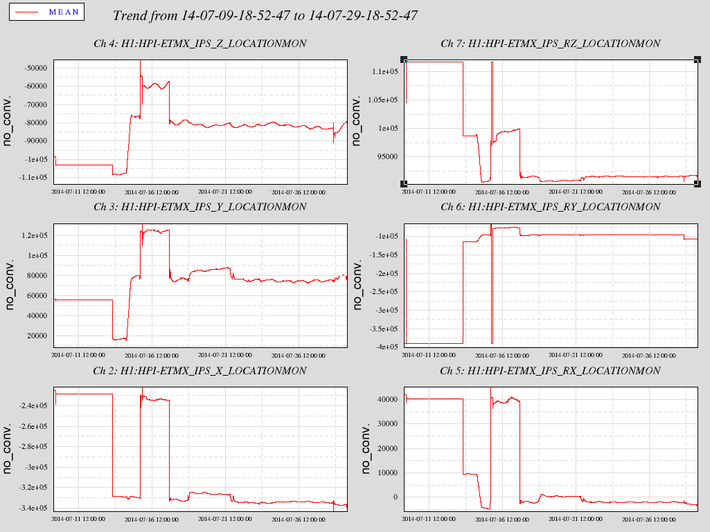
The Pump Station had only just recovered from shutdown Sunday July 13 and again shutdown on 17 July where it has remained. The attached 20 day plot of Cartesian basis position Dofs shows the shutdown clearly after a few days of flat position loop control, the step to Pump off position for a couple days, a step to Pump on but HEPI not Isolated for a couple days and then another step back to Pump off period for the remainder. The amount of shifting from Pump off to on is in the 10s of micro range.
The shutdown was due to the familiar OV3, overvoltage at constant speed. EE tells me we could possibly put some inductor on the line to reduce this.
Anyway, no problem getting this back on, usual process.
I'm looking at the performance of the IMC during ER5 (58.5 days spanning from Jan 15 12:00 - March 15 00:00 UTC) and thought I'd share some stats. I know it's only the IMC, but I think the numbers are quite good since work was continuing at the sites as normal.

I'm looking at times during this period where the IMC ODC reports the IMC was in a good state. One reason we cared about the state of the IMC during ER5 is because we were using recoloured IMC-F data as GW data in our search pipelines.

Below I've listed the percentage of time during this 58.5 day period where the IMC was 1) in a good state 2) in a good state for more than 60s 3) in a good state for more than 2048s. This last number corresponds to the length of data we need to run a CBC search. I've listed the time for LHO, LLO and Joint which means 2 detector coincidence (i.e. both were on at the same time).

|  Segment Length (seconds) | LHO | LLO | Joint |
|          > 0              |89.1%|66.1%| 57.7% |
|          > 60             |88.8%|65.9%| 57.3% |
|          > 2048           |80.7%|63.4%| 50.2% |

Punchline - for ~50% of ER5 we had sufficient coincident IMC data to run a CBC search.
Sorry the table formatted fine as a draft, here it is in pdf
MattH told me this morning they were ready for releasing the ISI, so I went down to EX just before lunch. The ISI is now floating, I haven't looked at cps numbers yet, but my understanding is nothing was added/removed from the suspensions and the lockers all felt smooth. Will check numbers in a bit, and tf's after the quad is unlocked.
[Arnaud P, Betsy W, Jeff K, Norna R, Stuart A,]

Matlab TFs were taken last night for the top stages on both main and reaction chains of the ITMY (QUAD) suspension, as follows:-

- ITMY M0-M0 undamped (2014-07-28_1090624828_H1SUSITMY_M0_damp_OFF_ALL_TFs.pdf)
- ITMY R0-R0 undamped (2014-07-28_1090642628_H1SUSITMY_R0_damp_OFF_ALL_TFs.pdf)

BSC1 ISI Status: ISI locked.

ITMY alignment: No offset was applied during this measurement.

The undamped TFs from above have been compared with the most recent set of 'good' measurements taken after IAS alignment and before being fully pay-loaded (allquads_2014-07-29_H1SUSITMY_Phase3a_Doff_ALL_ZOOMED_TFs.pdf).

Summary:

It can be seen that a R mode at ~2.6 Hz cross-couples into both L and most significantly V DOFs. Furthermore, this occurs for both main and reaction chains, so investigating the UIM stage for signs of rubbing would be first port of call.

All data, scripts and plots have been committed to the sus svn as of this entry.
[Stuart A, Arnaud P]

After the door was briefly removed from HAM3 to recover first contact from a witness optic (see LHO aLOG entry 12994) we repeated TFs again on PR2 & MC2 (HSTS) suspensions to verify that no issues had since developed, as follows:-

- PR2 M1-M1 undamped (2014-07-28_1090637500_H1SUSPR2_M1_damp_OFF_ALL_TFs.pdf)
- MC2 M1-M1 undamped (2014-07-28_1090619695_H1SUSMC2_M1_damp_OFF_ALL_TFs.pdf)

HAM3 ISI Status: ISI damped, no isolation loops running.

PR2 & MC2 alignment: No offset was applied during this measurement.

The undamped measurements from above have been compared with each other as well as the model (allhstss_2014-07-29_Phase3a_H1HSTSs_M1_Doff_ALL_ZOOMED_TFs.pdf).

Summary:

Both PR2 & MC2 M1-M1 TFs show good agreement with the model and perform consistently, thus raising no concerns.

All data, scripts and plots have been committed to the sus svn as of this entry.
J. Kissel

Betsy, Travis, and Jason have finished initial alignment of the Reaction Chain on H1 SUS ITMY. Over lunch, I've run a set of DTT transfer functions to confirm we're not rubbing in a way that would affect the IAS assessment. The TFs reveal the chain is free as a bird, so the IAS numbers are legit. Nice work, team!

They're beginning to "payload" the SUS now (add the stiffening sleeve, vibration absorbers, etc.), and we'll take a full set of TFs again tonight, including the Main Chain to confirm all is well.

All scripts and data have been committed to the svn.
False advertising. The main chain was rubbing at the close of business this day.
