david.barker@LIGO.ORG - posted 09:47, Sunday 27 July 2014 (13015)
CDS model and DAQ restart report, Saturday 26th July 2014
no restarts reported.
no restarts reported.
Patrick and Dave
at 14:52PDT cdsfs0 (file server for /ligo) encountered a error. All workstations are frozen due to loss of /ligo.
We are rebooting to see if we can bring it back.
The Hanford Fire Dept will be on sight doing some fire hydrant flow measurements. Should be done around noon.
Hanford Fire is done testing Hydrants for the day. Thank you Mike Pedraza for shutting off the Pumps for me. They could not test Hydrant 11 still out of service due to leak nor Hydrant 7 which has a broken valve.
model restarts logged for Fri 25/Jul/2014
2014_07_25 10:25 h1odcx
2014_07_25 13:56 h1odcx
no unexpected restarts. PCAL work at EX.
Mike V, Richard S, Shivaraj K and Darkhan T

Pcal efficiency measurements were taken at EndX on 07/22/2014, 07/23/2014 and 07/24/2014.

We took in-chamber and out-of-chamber measurements on 07/22/2014 and saw >2% power drop between transmitter output and receiver input (overall efficiency). On the same day during several measurements in the beginning halogen chamber illumination lights were turned on. During measurements on following days we kept halogen illumination off.

Since major power drop was between transmitter output and ETMX input (viewport+periscope), on 07/23/2014 before taking any measurements we wiped some of the periscope mirrors.

By now we have
* 3 samples of in-chamber measurements, efficiency of ETMX at Pcal laser wavelength (1047nm) and two viewports separately;
* 5 samples of out-of-chamber measurements, for overall efficiency calculations.
| Date, sample # | 07/22/2014 | 07/23/2014 sample 1 |
07/23/2014 sample 2 |
07/24/2014 sample 1 |
07/24/2014 sample 2 |
| Efficiency of the viewport at transmitter module | |||||
| inner beam | 0.9870 | 0.9936 | 0.9943 | ||
| outer beam | 0.9756 | 0.9916 | 0.9892 | ||
| Efficiency of ETMX (reflectivity) | |||||
| inner beam | 0.9975 | 1.0003 | 0.9986 | ||
| outer beam | 0.9938 | 0.9978 | 0.9993 | ||
| Efficiency of the viewport at receiver module | |||||
| inner beam | 0.9935 | 0.9951 | 0.9960 | ||
| outer beam | 1.0021 | 1.0008 | 1.0011 | ||
| Overall efficiency | |||||
| inner beam | 0.9781 | 0.9890 | 0.9890 | 0.9858 | 0.9876 |
| outer beam | 0.9717 | 0.9902 | 0.9897 | 0.9836 | 0.9848 |
Took a snap shot of the ITMY HEPI position at various times: IAS align good (Tuesday Rz & X), SUS completes payload hanging on ISI (Wednesday Rx & Ry), and finally today when the ACB was hung on. I'll hold the positions to these times. With the ACB install the Z has shifted down seemingly a lot but actually only 160000nm. I've closed the loop and used this target and the loop is fine but it isn't our practice to 'target' the Z DoF. Rx & Ry I do want to hold although again the amount of shift isn't huge: -78000 & 20000nrads. But this is tilting HEPI and changing the hang of the ISI stages although likely not to 1st order; our level Spec on ISI is 100urads. Y shift from alignment time to now in only 4um.
Target values: X/RX/RY/RZ == 300000/15000/56000/-16200
Previously as reported, the Ry loop has not been stable; interestingly it seems to be happy now. Of course the ISI & SUS both were locked for the ACB install...
Meanwhile, I have Guardian controlling HEPI for all DoFs and holding position on X, Rz, Rx & Ry. We'll try to off load the X, Rx & Ry to the HEPI Springs at a later time. Yeehah!
Matlab TFs are set to run on HAM2 suspensions overnight as follows:-

- MC1 (HSTS) M1-M1 undamped TFs
- MC1 (HSTS) M2-M2 undamped TFs
- MC1 (HSTS) M3-M3 undamped TFs

- MC3 (HSTS) M1-M1 undamped TFs
- MC3 (HSTS) M2-M2 undamped TFs
- MC3 (HSTS) M3-M3 undamped TFs

Starting now, and when complete the measurement status will revert to OFF and damping loops will be restored to the ON state.

n.b. all stages of the above suspensions have been configured to Coil Driver BIO state 1 to try and limit any DAC saturations.

These measurements have been initiated from the opsws2 workstation.
PRM PR3 (all stages) and MC2 PR2 (M2 M3) started around 4:40 on opsws1. HAM2 ISI is Isolated HAM3 ISI is Damped.
Mitchell R, Mike V, Travis S
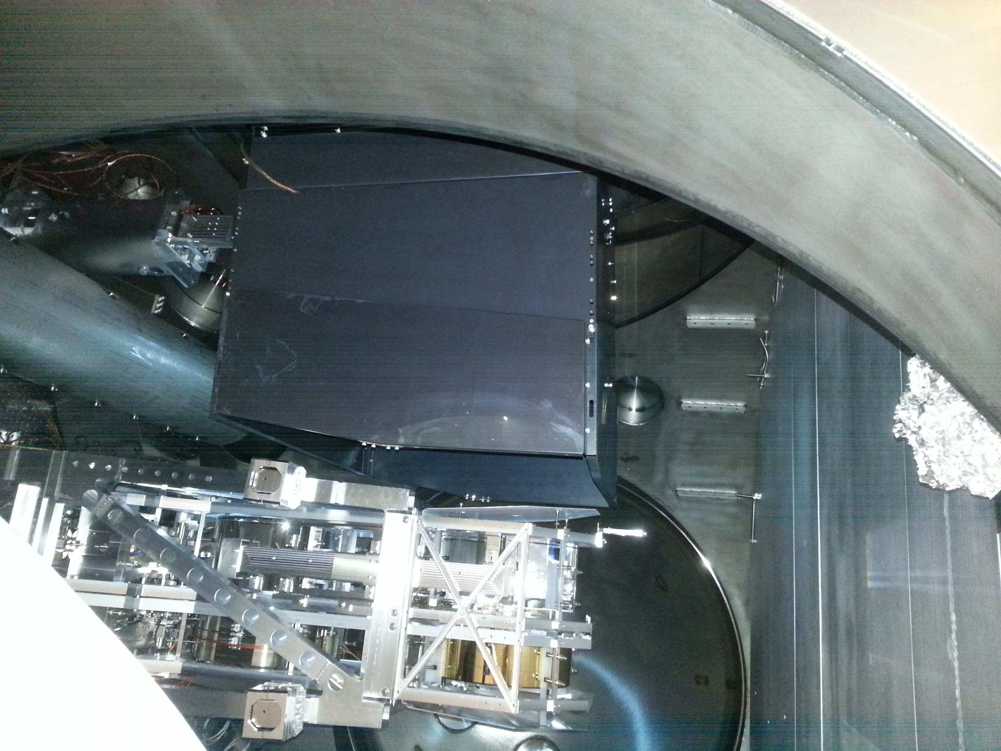
Today the ITMY ACB suspension and box assemblies were installed in BSC1. There is good clearance with respect to the ITMY suspension.
Pushers and clamps are installed in preparation for alignment work to commence on Monday.
The photodiode cable is still to be connected followed by a functionality check by Richard M.
The full payload is not in place; masses currently at clean and bake will be installed Monday, followed by a short period of balancing.
Attached is a photo of the installed baffle, along with a bonus shot of a happy Mitch.
Just for interest what was the particle counts ? Interested to see how much stirred up during this work
8:15-8:45 Morning Meeting
8:50-11:30 Heading into the LVEA to continue with HAM2/3 work – Matt/Jeremy
8:55-11:30 Contamination & Control work in LVEA - Jeff B
8:59-12:00 Going to End Y to work on illuminator – Aaron
9:15-12:00 Working on Optics Lab/Laser ON – Nathan
9:35-11:24 Locking/ Unlocking suspension in LVEA (BSC1 & BSC3) – Travis
9:39-11:24 Heading into the LVEA to work on ACB – Mitchell/Mike V.
9:52-12:18 Stage Viewport Preparation in LVEA – Gerardo
10:20-12:18 Joining Gerardo in the LVEA for Electric Field measurements – M. Laundry
10:22-11:30 HAM 2 testing in LVEA – Stuart/Arnaud
10:24 - Restarting h1odex model - Dave
12:13- 14:50 Heading back to the LVEA – Matt/Jeff B/Jeremy/Apollo
12:17- 14:50 Heading back to the LVEA – Stuart/Arnaud
12:43-     Going to End X to work on illuminator – Aaron
13:12-13:56 Working at End Y – Karen
13:18-     Replacing BSC2 ISI chassis in Electronics room – Filiberto
13:40-LVEA transitioning to Laser Hazard – Richard
14:21-12:18 Back to the LVEA for Electric Field measurements – Gerardo/M. Laundry
14:23- LVEA transitioning back to Laser SAFE – Richard
14:37- 15:40 Returning to the LVEA to work on ACB – Mitchell/Mike V.
model restarts logged for Thu 24/Jul/2014
2014_07_24 05:18 h1fw0
unexpected restart of h1fw0
Summary: Eight years of wind data at 3 LHO stations were analyzed. Fifteen percent of hours had wind speeds exceeding 10 m/s, the speed at which displacement and tilt from wind start to significantly increase the seismometer signals. Nearly 25% of hours in April, the month with the highest average wind speed, have winds exceeding 10 m/s. Data are also shown for individual stations; readings for EY are the highest.
Introduction: The analysis of wind data is important because wind speeds over 10 m/s increase ground motion and thus affect interferometer performance. This increase in ground motion is caused by wind interacting with the topology of the site and, most importantly, the surfaces of buildings. In addition to producing displacements, wind blowing on the buildings can tilt them, which can produce spurious acceleration signals from seismometers.
Methods: Eight years of data between 2004 and 2012 were analyzed for patterns across the years. The data was extracted from DataViewer for the Corner Station (CS), End Station X (EX), and End Station Y (EY). The "Maximum Channel" was selected of the "Hourly Trend" setting within DataViewer. This time period was selected because it was not missing more than 58 days of data at a single time in the series and only a total of 218.7 days were missing from the entire data source. This amounted to about 8% of the data missing from the entire data set. The data was considered missing if DataViewer did not provide it.
Results: The first figure shows that 15% of the hours in the 8 years analyzed exceeded 10 m/s, which significantly increases ground motion. The second figure shows that, during each of the spring months, the wind was greater than 10 m/s in more than 15% of the hours, peaking at 24% in April. The third figure shows that the average hourly maximum wind speed varied the most from year-to-year in the month of February. The fourth figure includes statistics for the individual stations. Averages for EY are higher than for other stations. For example, 27% of April hours exceed 10 m/s at EY while the average for all stations was 24%.
Margarita Vidrio, Robert Schofield
In Fig 5, the wind speeds exceed 10 m/s thirty eight percent of the time in June at 2 AM and April at 11 PM. Also, the month of December shows a consistent percentage (between 8%-10%) of wind speeds over 10 m/s across all times of the day.
Jeremy B, Stuart A, Jeff K, Arnaud, Jeff B, Matt H, Apollo, Richard M
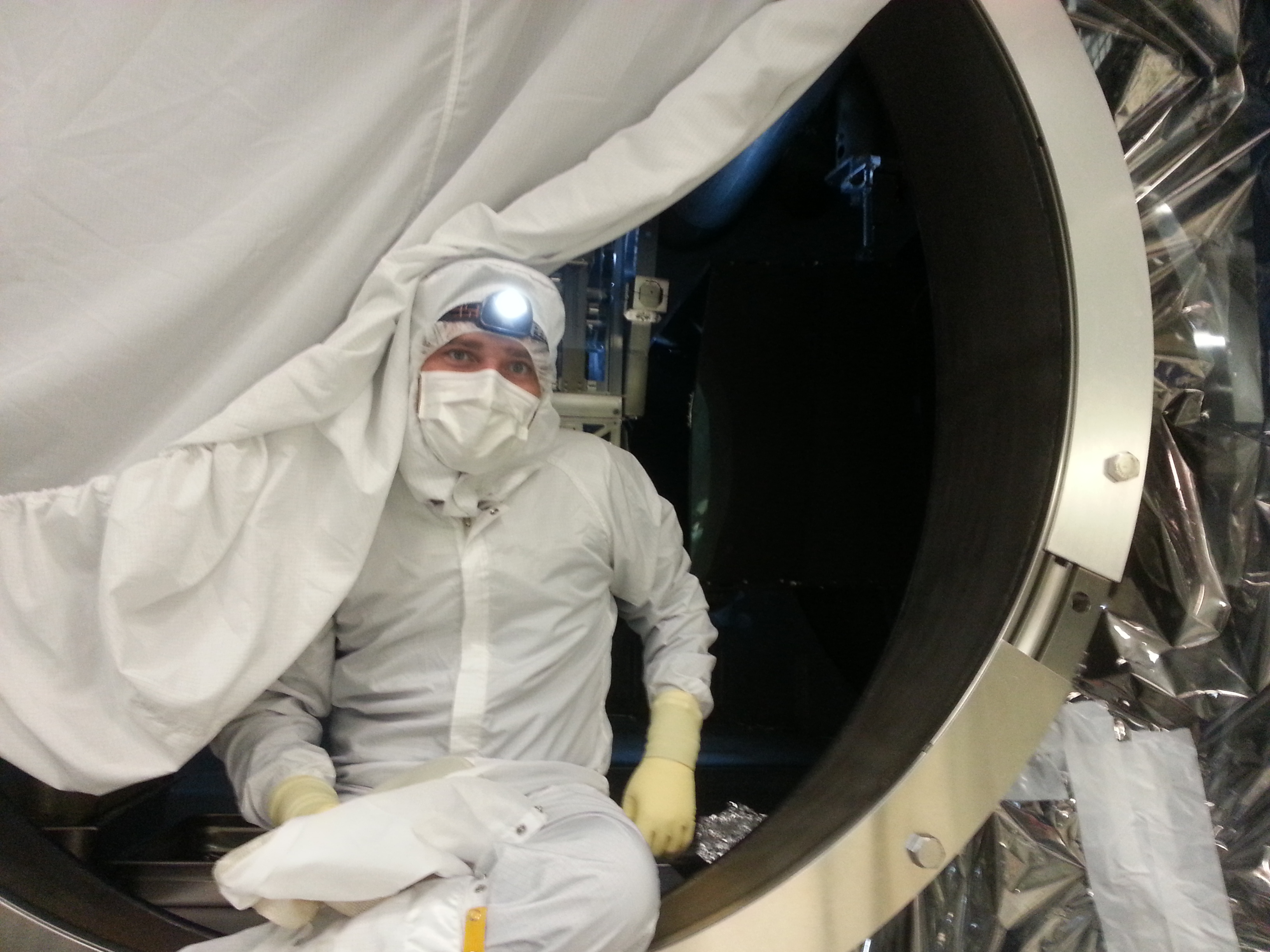
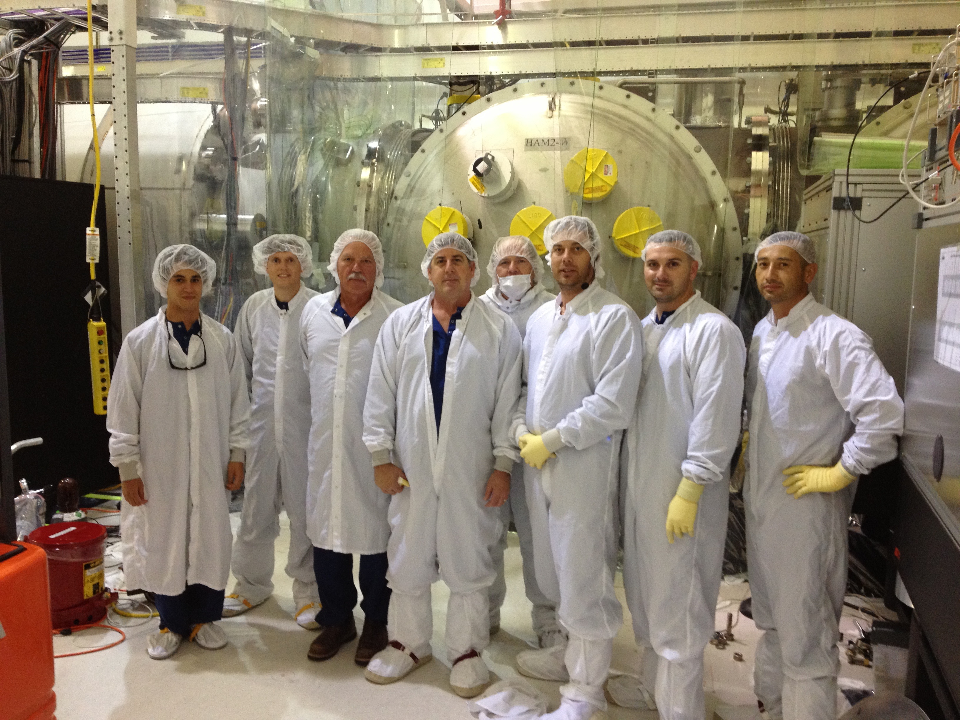
Success....HAM2 closed up :-)
Quick rundown of events.
Entering HAM2 straight after doing door work on HAM3 and the particle counts were zero. We had some troubles with PRM showing signs of rubbing overnight so we looked at this first. I didnt find anything glaring but saw a couple stops kinda close. We backed these off ran another set of TFs and got a clean bill of health. Then to save time later we centered all ther OSEMs on all four suspensions on all stages. After this I locked all four HXTs's to get ready for FC pull
Jeff B went in and did a quick last wipe down, put in wafer and monitor optic, removed optics/wafers that were still in chamber, etc. We were all straged to pull FC but couldnt get low particle counts. People were working in BSC's so asked the to stand down to let the particle counts drop.
After a quick lunch to let the particle counts settle, it was all systems go. On the way out we bumped into Mike Landry et. al. who had been doing tests with the large optics/top gun. I am sure he will write a report on his work but he indicated it took ~9mins for the fields to drop. Thus we decided we should blow the smaller optics for 5mins continuously with the top gun after FC pulled. As I was worried about the pony sized bottles running out we dragged a large cylinder out there for the top gun.
Particle counts showed us good to go and so we pulled PR3, then MC1 then PRM FC. I went for MC1 now due to the awkwardness of having to unlock that suspension and how have to get on the table to do so. And I didnt want to do this with a half unlocked ISI. I inspected each optic for particulate and Arnaud/Stuart have a log of what I saw (which they will post). We also pulled the FC on the moitor optic. After I reminded myself about 50 times about it :-). We actually had to pull FC twice on it as after I pulled the outer layer, we saw there was still FC on the backside, so had to remove optic to pull backside FC and put optic back. Afte unlocking those three suspensions, TFs were taken on all three by Jeff K/Arnaus and given the all clear. Once the all clear given, the ISI was unlocked on east side and door went on.
Whilst door being put on on east side I pulled the FC on the MC1 suspension (particle counts were low), and unlocked the suspension. We found we had to change some of the OSEM positions on the three stages. TF's were taken on this suspension and given the all clear. Whilst TFs were being taken, Richard M transitioned us to laser hazard, and I visually inspected the ISS array cables one last time and they all looked plugged in.
Once TF's were given the okay, the offset settings for the MC mirrors for when we flashed the mode cleaner successfully in the past were applied and the mode cleaner flashed right away. YES.
ISI on west side unlocked and door went on :-) :-)
Stuart/Arnaud have a detailed log of particle counts/timeline/particles per square inch on the optic which will post to this log
Pic: The HAM closeup crew. Thankyou to all who have helped get LHO to this point. Its amazing to be to this point and when we had schedulded it
Attached below is a log and particle counts taken during the HAM2 work covering the period 1056 (local) to 1431 (local). Thanks to Arnaud for logging the afternoon session.
Jeremy B, Matt H, Jeff B, Apollo
As you may remember from one of my alogs last night, i forgot to pull the FC on the witness optic in HAM3. It was decided to play it safe and pull the door to get at it. So before anyone else started in chamber work we quickly pulled the door. Particle counts in cleanroom were 10 counts and straight after the door came off was also 10 counts in chamber. Door came off at 9.09 am, Half the ISI was locked....and whilst ISI was being locked I looked at MC2 optic. Looked same as yesterday which is awesome. I tried pulling the FC on the small optic and in doing so it ripped so I only had a little bit come off with first go (I think the layer was to thin). So had to try to get at it with a gloved hand to get the rest. We did so, but it definitely meant that the cautious approach was the right one. We did a quick check to make sure we got all the FC, unlocked the ISI and the door went back on at 9.22am (off for around 13mins). Jeff checked particle counts as the door was jamming shut with the chamber and saw no puff of particulate.
Stuart has a detailed log of timeline and particle counts that hoping he will add to this
Attached below is a log and particle counts taken during the HAM3 work covering the period 0900 (local) to 0922 (local).
Matt H. requested that we verify the ISS PDs were still connected in vacuum. I was able to get to the all 16 cables and tested each pair. They all tested fine with a reading of approximately .384VDC Anode to Cathode and OPEN Cathode to Anode on my Fluke 87V set to diode test. The last set I tested seemed to be reversed so I left them disconnected until I can have better access to the chassis under the chamber behind the HEPI support Structure.
Below is the instructions I received from Peter K and passed on. Thanks Richard for doing this
The only way to test all the diodes without laser light is to use the diode
tester function of a multimeter. To do that you'll have to disconnect the
cables from the electronics that's where they were when we put the array
in. With the multimeter on diode test, the negative (black) lead goes to the
cables/connector labelled cathode. The positive (red) lead goes to the ones
labelled anode. Touch the centre pins of the cable SMA connectors. If
everything is okay you'll get a buzz and a voltage reading just over 0.3 V
(either 0.38 or 0.34, don't remember exactly which).
J. Kissel, R. Schofield

I discovered a lonely, forgotten, disconnected GS13 hiding under BSC9 (H1 ETMX) chamber today. I attach pictures.

Things that Robert and I can surmize:
- It's serial number is 574, and has a "property of the USGS, greater than $5k" sticker on the side with the number G12077 and a bar code.
- It may have been used for S5/S6 feed-forward studies (Will check with Mike, Keita, Richard)
- Ski may have purchased it, given the bar-code on the side (Will check with John)
- It's a 2005-ish era model, based on the color of its can and unfinished look of the feet.
- It's currently configured as a horizontal
- It claims of a broken locking mechanism, but after a few turns the mass seemed locked enough for transport
- It's functionality is unknown.

Finder's keepers ...
J. Kissel for R. McCarthy, M. Landry, K. Kawabe, R. Schofield, B. Lantz, and J. Giaime

Various hazy memories have added up to a conclusion: this above mentioned GS13 was part of the S5/S6 differential feed-forward work on H1. It's pair at EY is also disconnected, but is in more "formal" storage on the wire racks in the change room / air lock before the YVEA. There're actually two on that rack, I attach pictures of both. Robert believes the other is "his," i.e. purchased with PEM dollars (though does not know which is whose). Lantz and Giaime believe the non-PEM GS13s were originally purchased for LLO's PEPI prototyping.

In summary -- three GS13s, all in the horizontal configuration, serial numbers:
574     EX, under BSC9
578     EY, on cleanroom racks
584     EY, on cleanroom racks
All have custom readout cables attached, with signal readouts on a BNC and power on a 4-pin lemo.

574 claims to have a broken locking mechanism, and 578 is missing it's back, adjustable leveling foot. Interestingly, the locking knob on 584 has a groove carved out of it. Perhaps this might have been used to prototype a locking mechanism (originally a part of the aLIGO design before Stanford innovated the lock-free GS13s we have today).

And now you know... the rest of the story.
J. Kissel

I found *another* disconnected, unpodded GS13 sitting in the North East (+X,-Y) corner under BSC5 (H2's ETMX) chamber. His serial number is 568, and has a similar property barcode on it as the others, and it's configured as a vertical, so my guess is that each end station had an horizontal and a vertical. The EY one's are locked up, and I didn't bother checking their configuration. They're marked as "H" on the horizontal leveling feet, but that is not necessarily indicative of the configuration since they get changed and the label is oft-not updated. I attach pictures.

I locked the instrument, and brought it out the change room (similar to where S/N 578 and 584 are stored at EY).

This brings the collection up to:
S/N     Config      Current Location
568        V        EX, in change-room, by bench
574        V        CS, In my office
578        ??       EY, on change-room racks
584        ??       EY, on change-room racks


/ligo file system is back. I tried to remotely power cdsfs0 down, but it got stuck in the process. Patrick powered it down using the front panel button, then powered it up. It did not do an automatic fsck and rebooted quickly. All systems appear to have reconnected to the file system seamlessly.
I checked the vacuum alarms to cell phones and MEDM screens to web are working. I verified the DAQ was unaffected. Patrick says the workstations in the control room became unstuck without any reboots needed. Some workstations are locked out by users and may have been running transfer functions, Patrick is emailing the relevant commissioners to check their TFs.