Kate G, Calum T, Rich A, Matt H
First of all a BIG/MASSIVE/ENORMOUS thankyou to Calum, Kate and Rich for putting up with a slave driver like me and working a 12 hour shift with me on a saturday
Standing of chambers at the moment as I remember it:
HAM2
PRM..locked…however still need to lock optic barrel stops and remove front optic EQ stops..then ready for FC
PRM baffle…removed
PR3..locked. Ready for FC
MC3..locked…however still need to lock optic barrel stops and remove front optic EQ stops..then ready for FC
MC1..partially locked
Kapton washers not installed on picomotors yet
ISI…locked
HAM3
MC2…FC applied and unlocked
PR2….FC applied and unlocked
Large Kapton washers installed on all picomotors
ISI…unlocked
Covers pulled back from ISI
Coarse wipe down of chamber has occurred
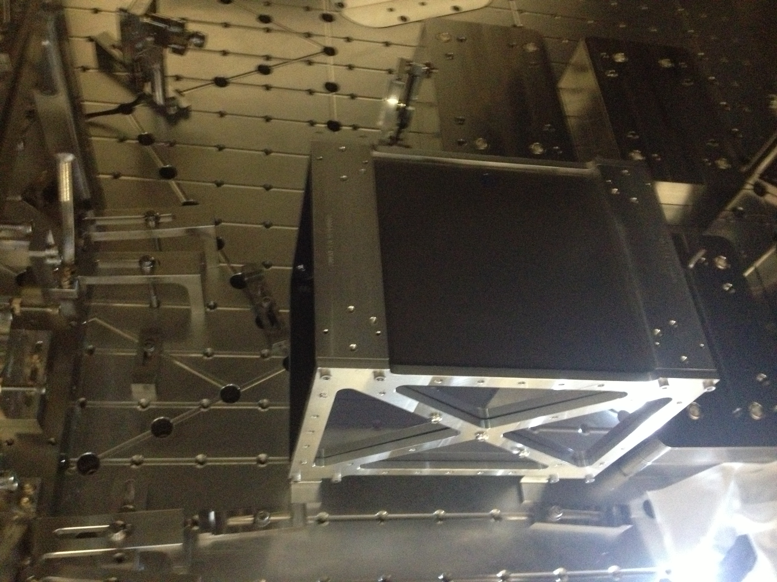
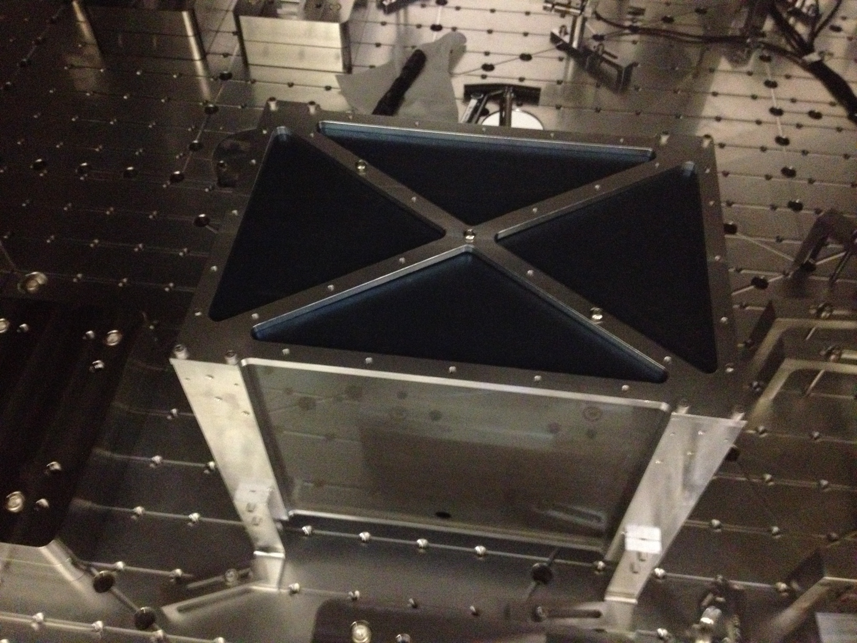
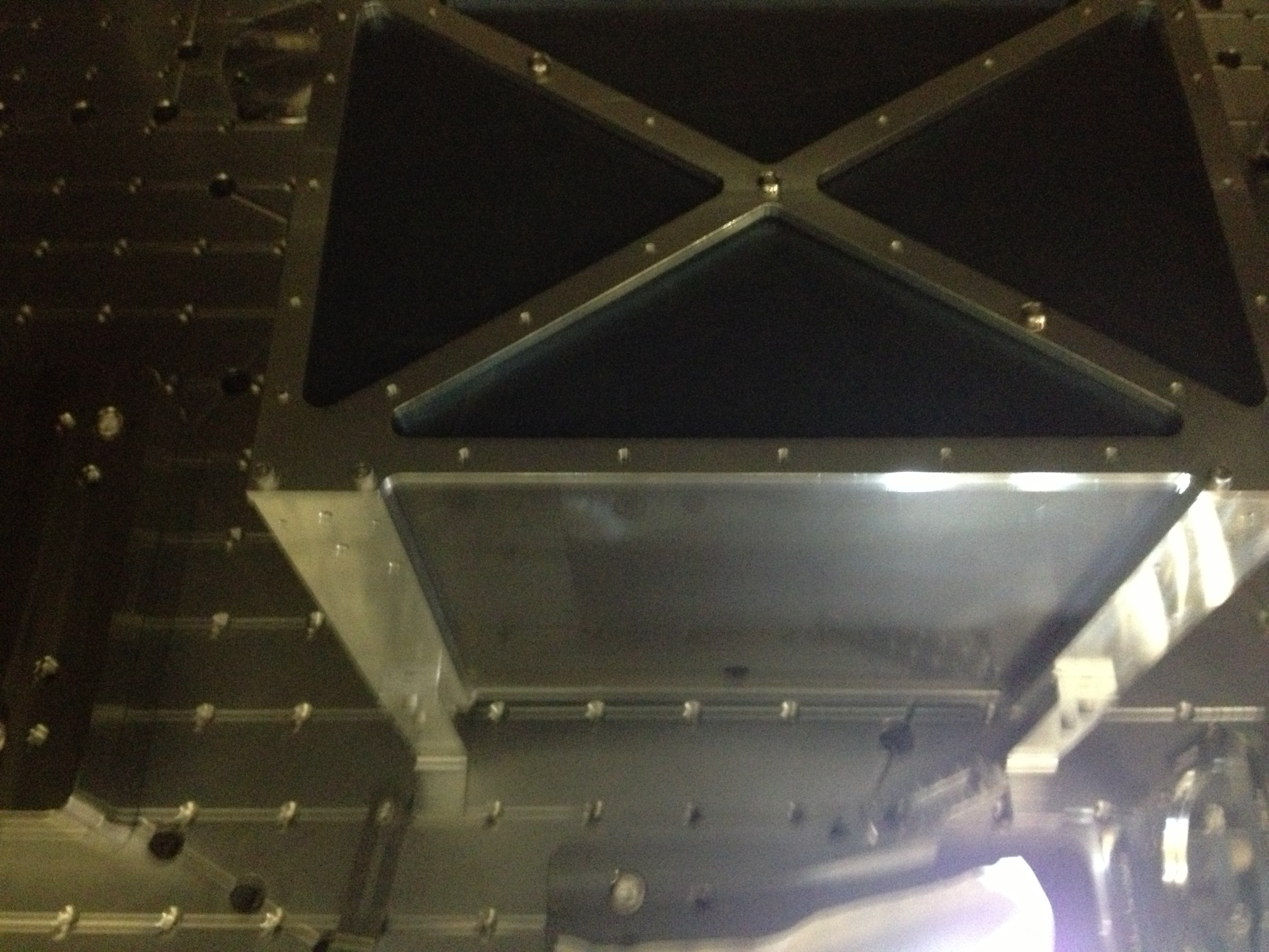
BSC2
Beamsplitter optic…locked
ISI…locked
First contact applied to optic...still need to paint "crust"
New baffle installed
Old baffle needs to be reinstalled after FC pulled
Chamber wipe down occurred
HAM4
SR2..locked…however still need to lock optic barrel stops and remove front optic EQ stops..then ready for FC
TCS optic in front of SR2 optic removed
ISI…locked
HAM5
Faraday..unlocked
ISI…locked
SRM…locked…no FC will be applied
SR3…locked. Spray FC applied, need to paint edges
SR3 front baffle removed
Chamber wipe down occurred
BSC3
Suspension..locked
FC applied to optic…..still needs outer crust applied I believe
Arm cavity baffle still pulled back I believe.
Particle counts
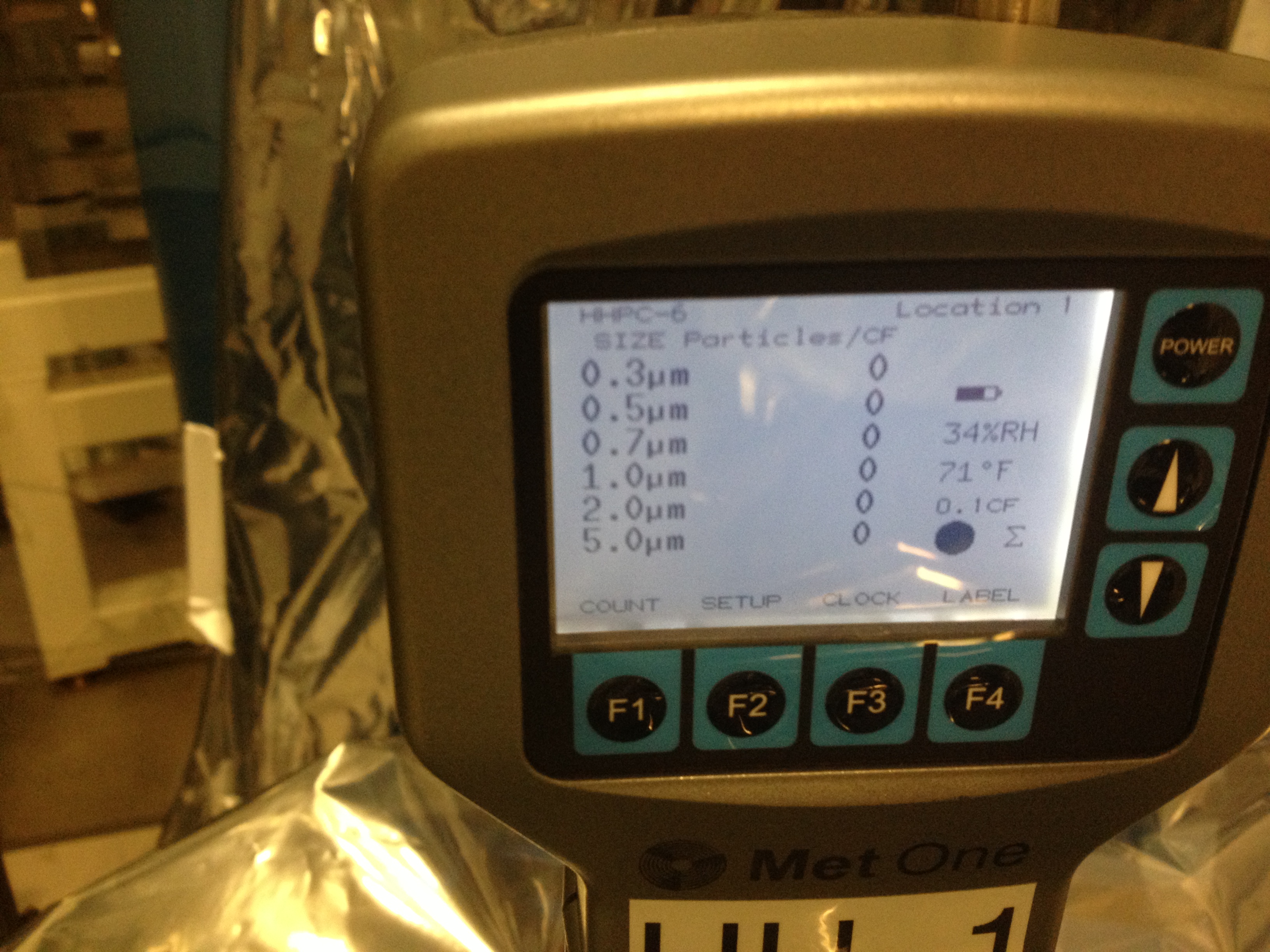
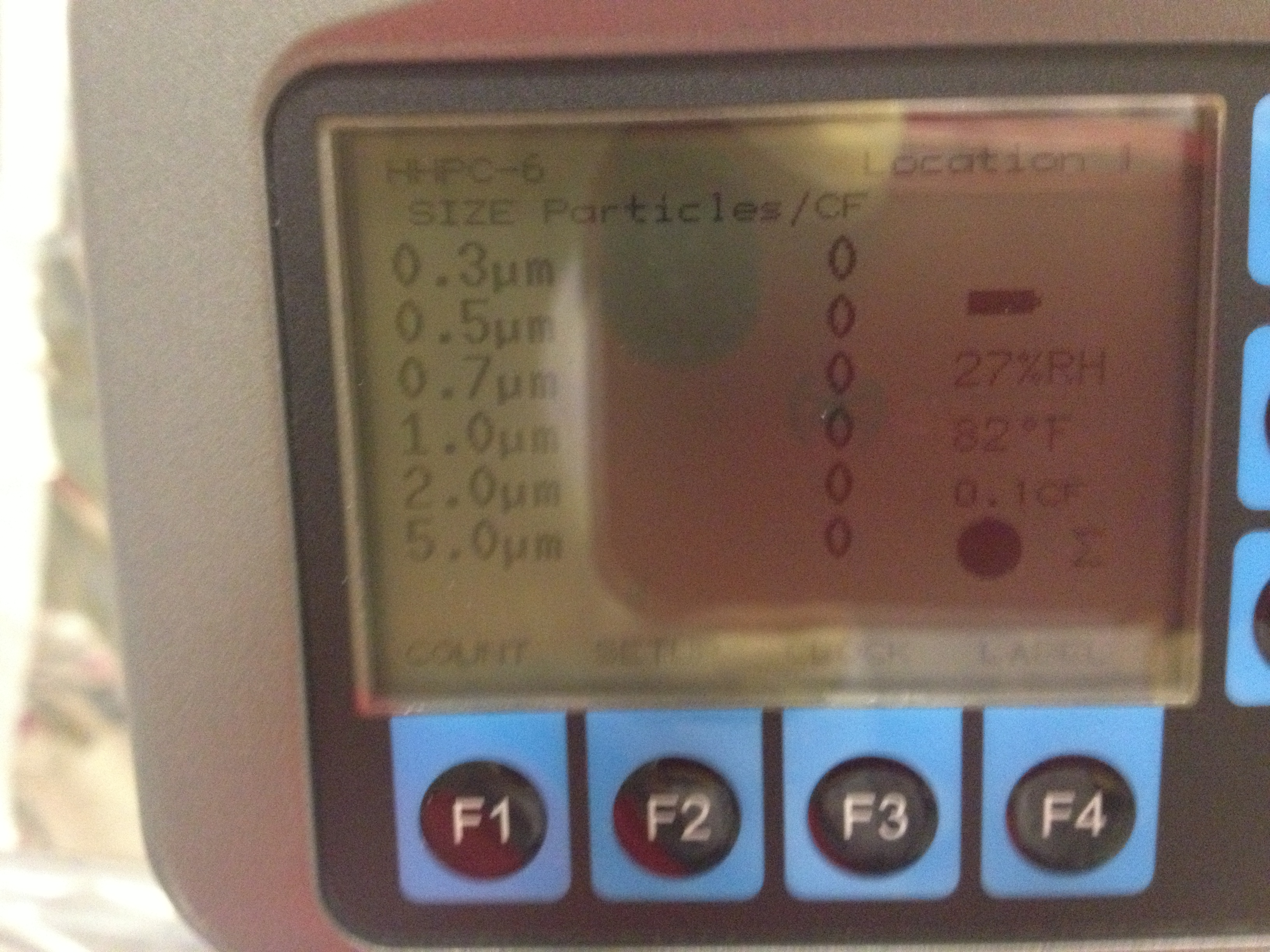
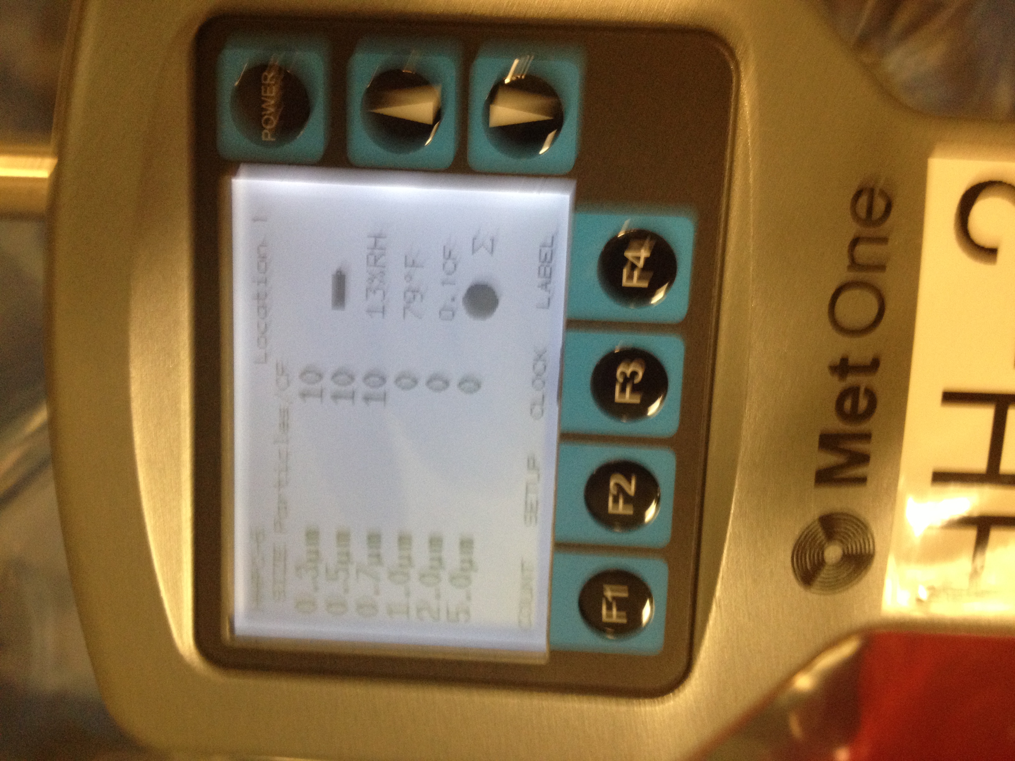
HAM4
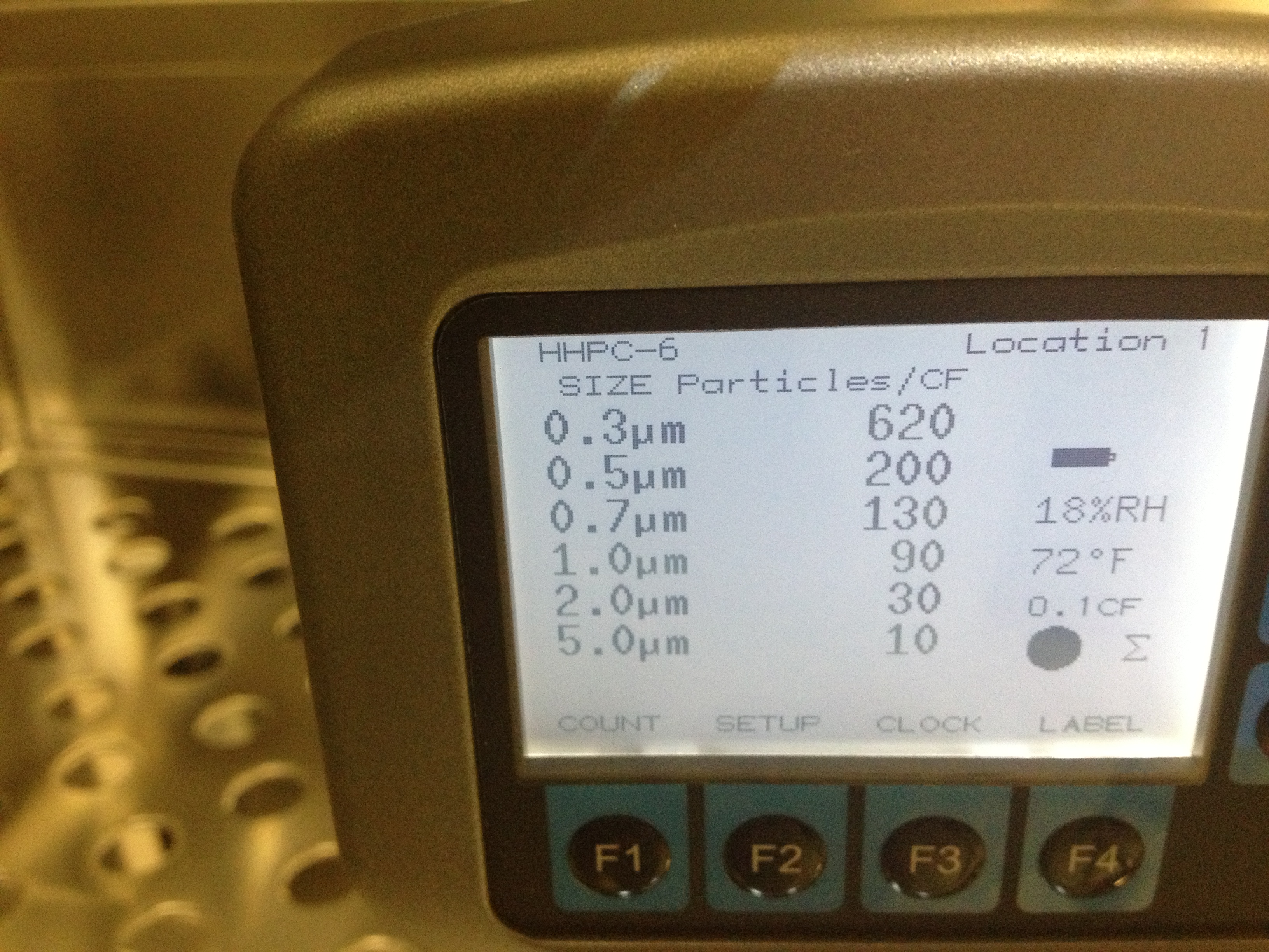
In cleanroom start of arvo session
All counts zero
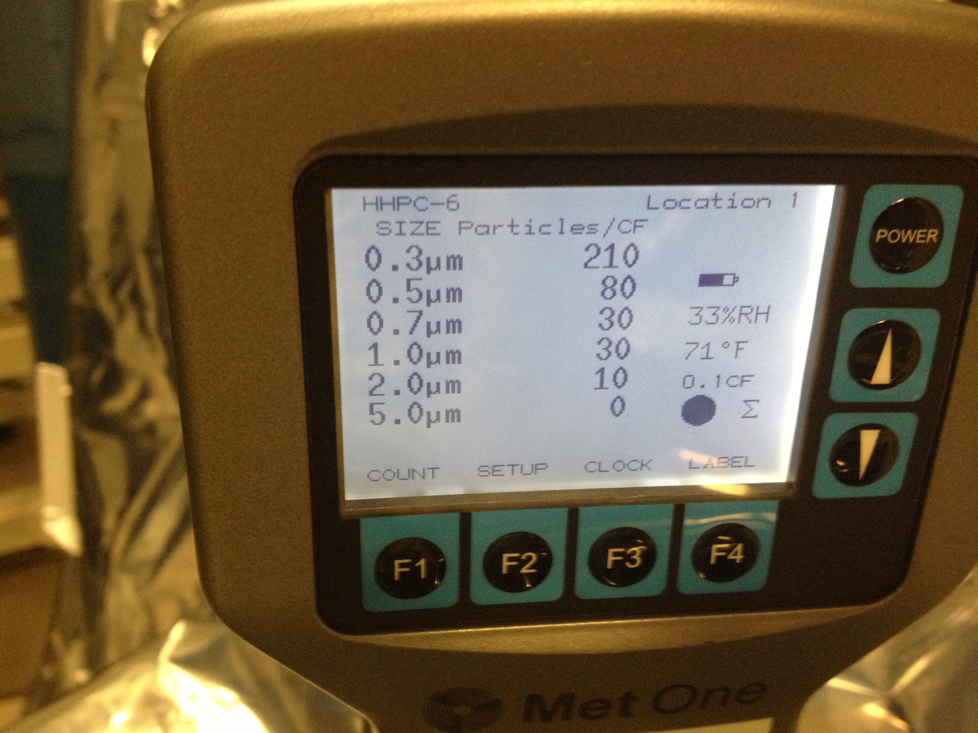
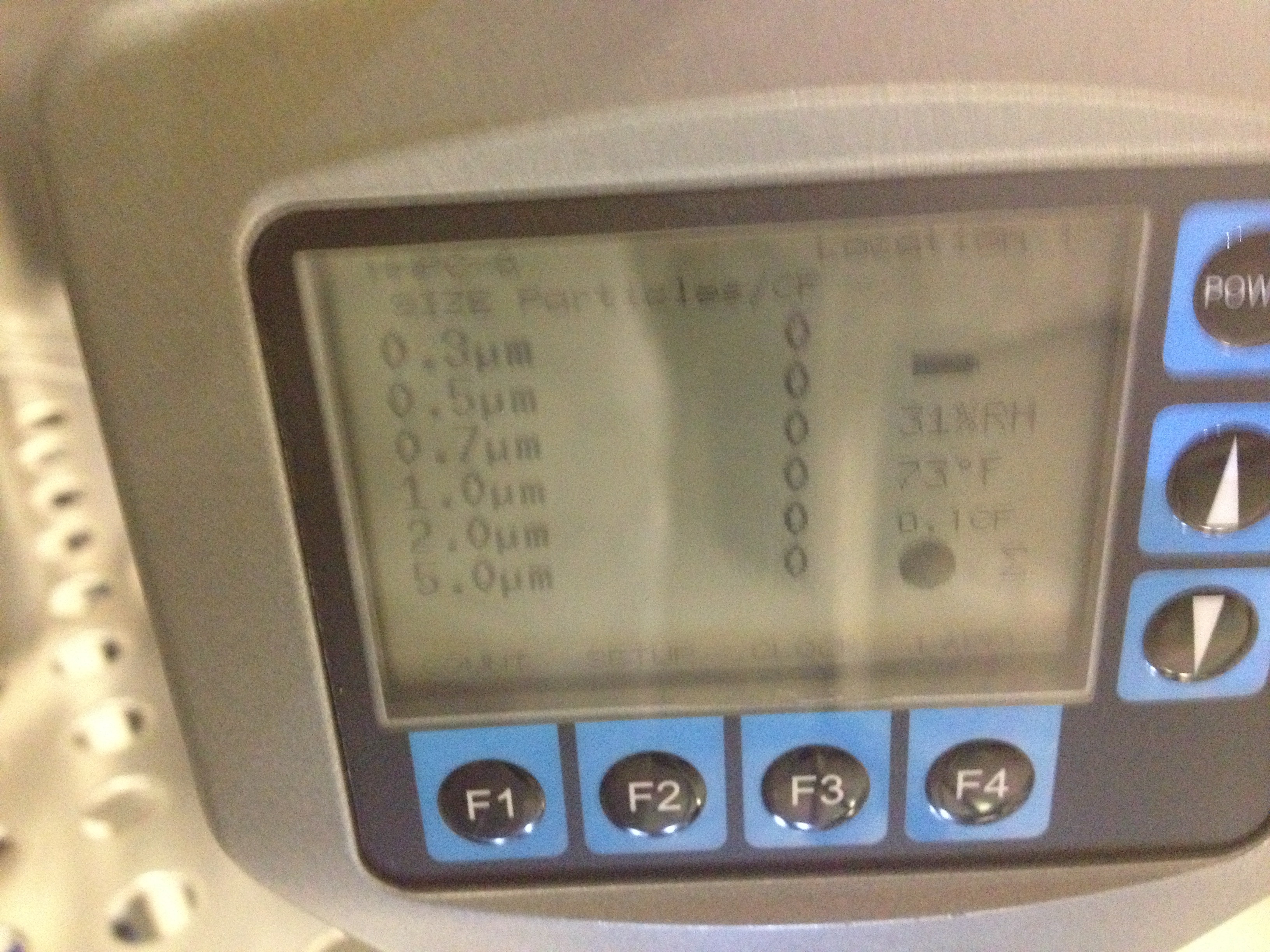
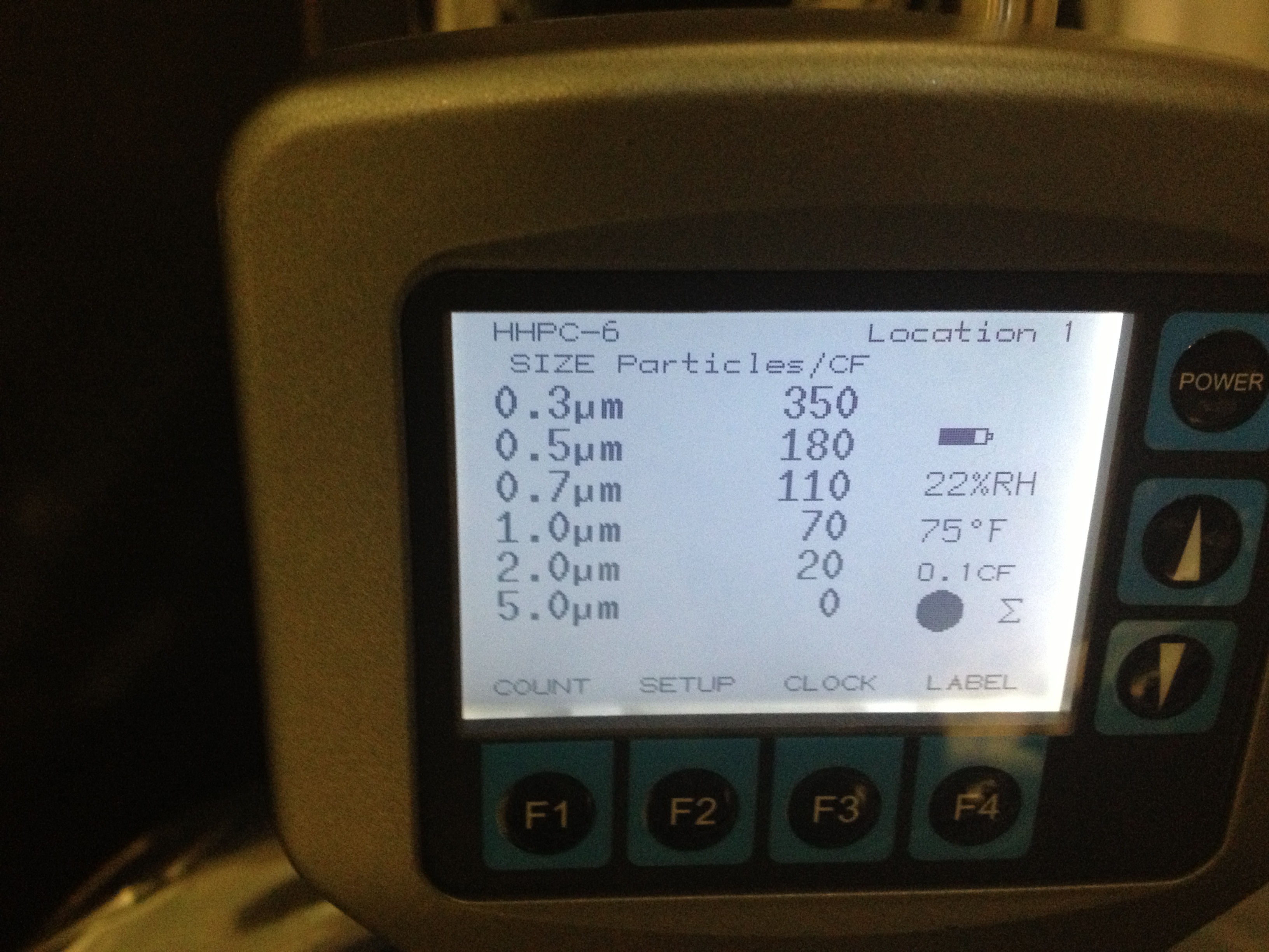
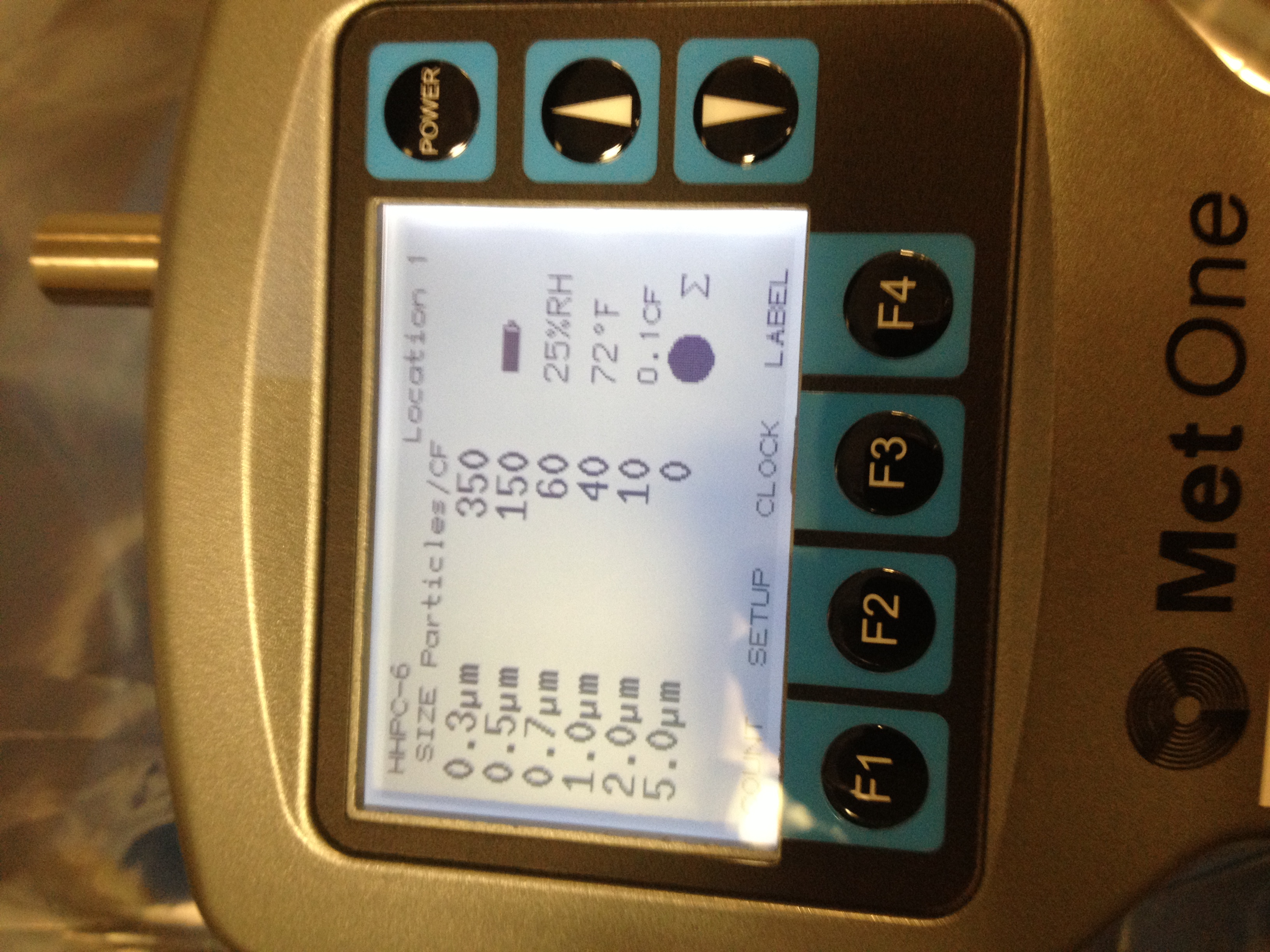
In chamber start of arvo session
0.3um...210 counts
0.5um...80 counts
0.7um...30 counts
1.0um...30 counts
2.0um ...10 counts
5.0 um....0 counts
Probably high due to baffle work
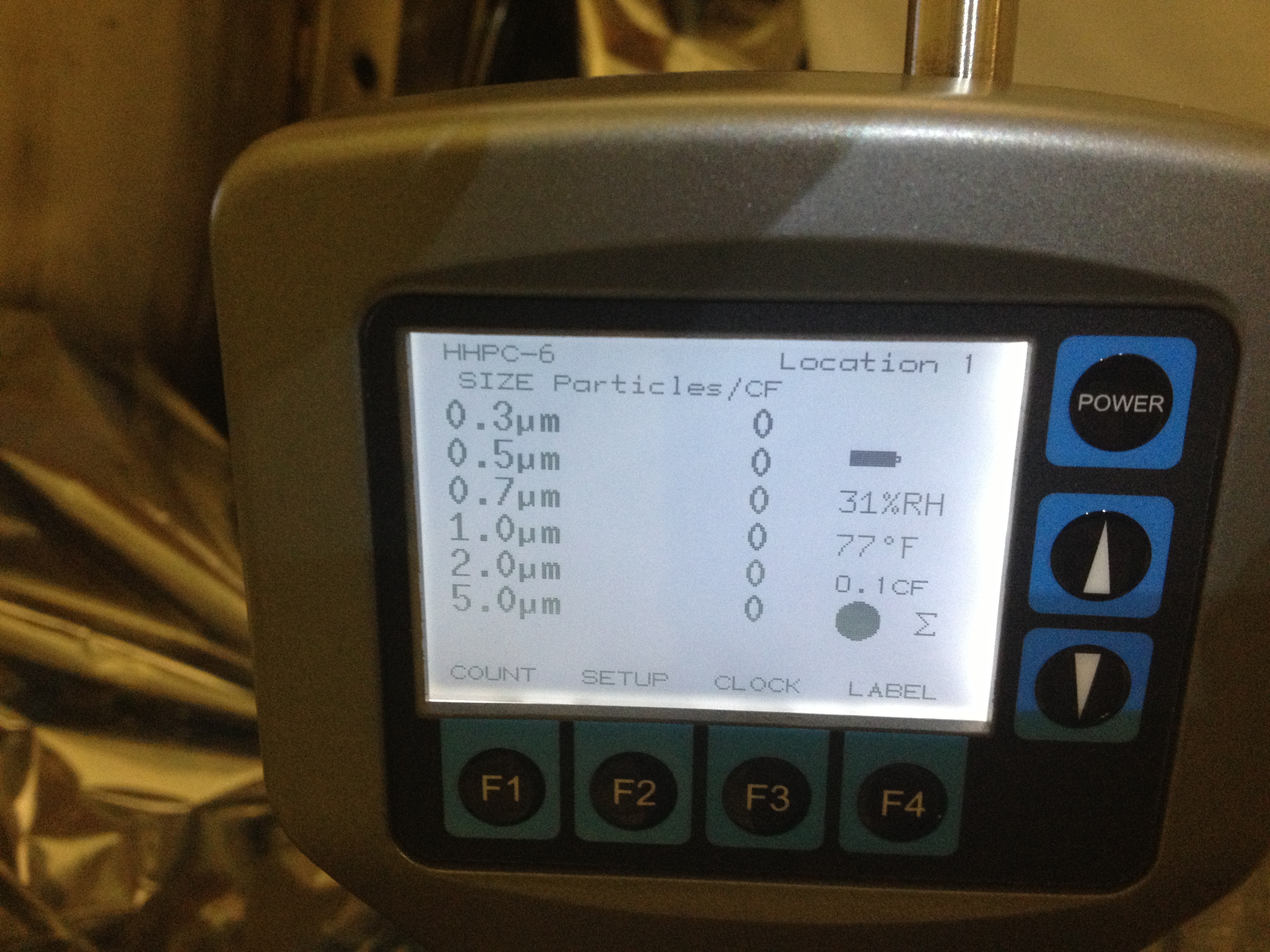
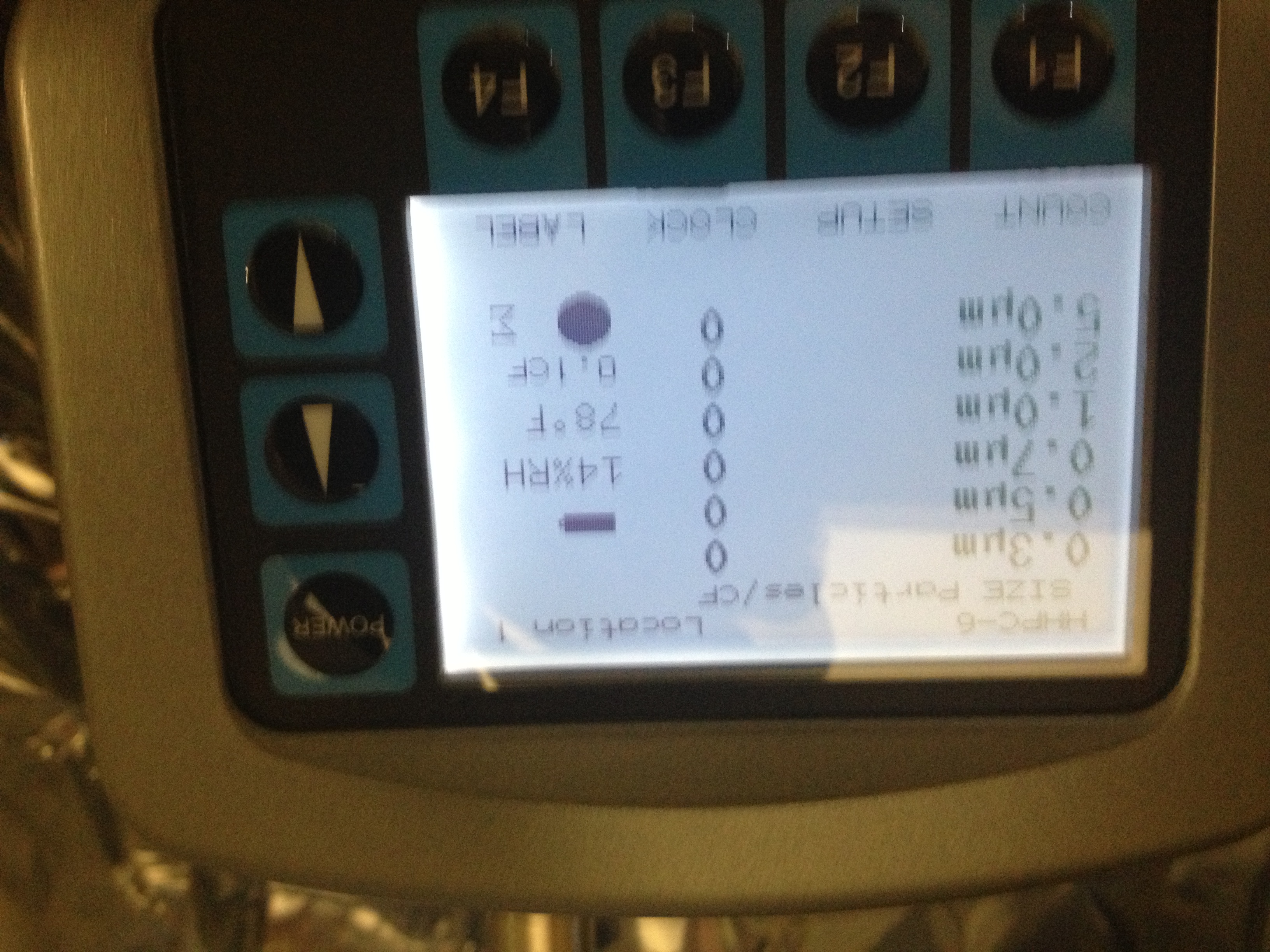
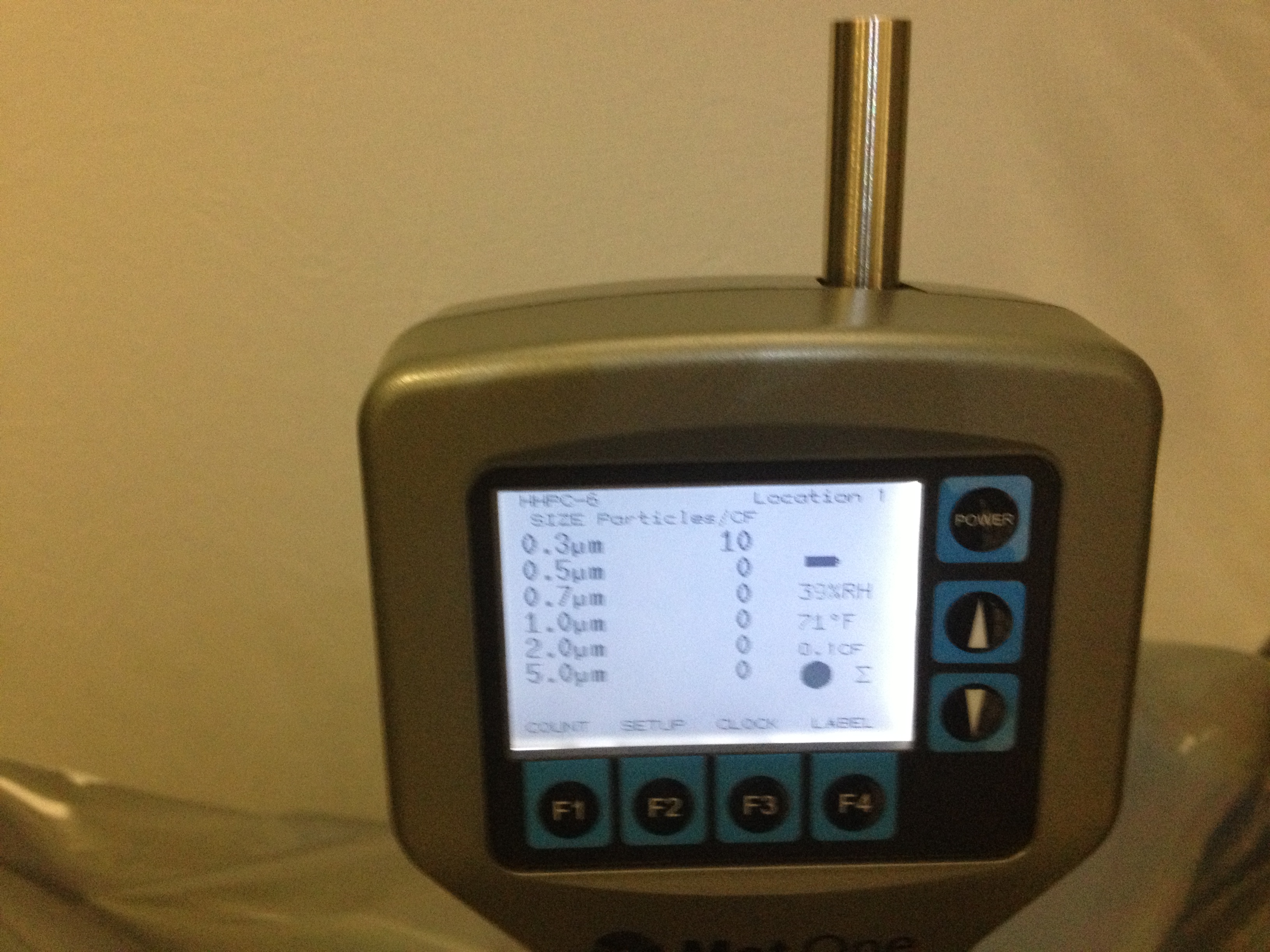
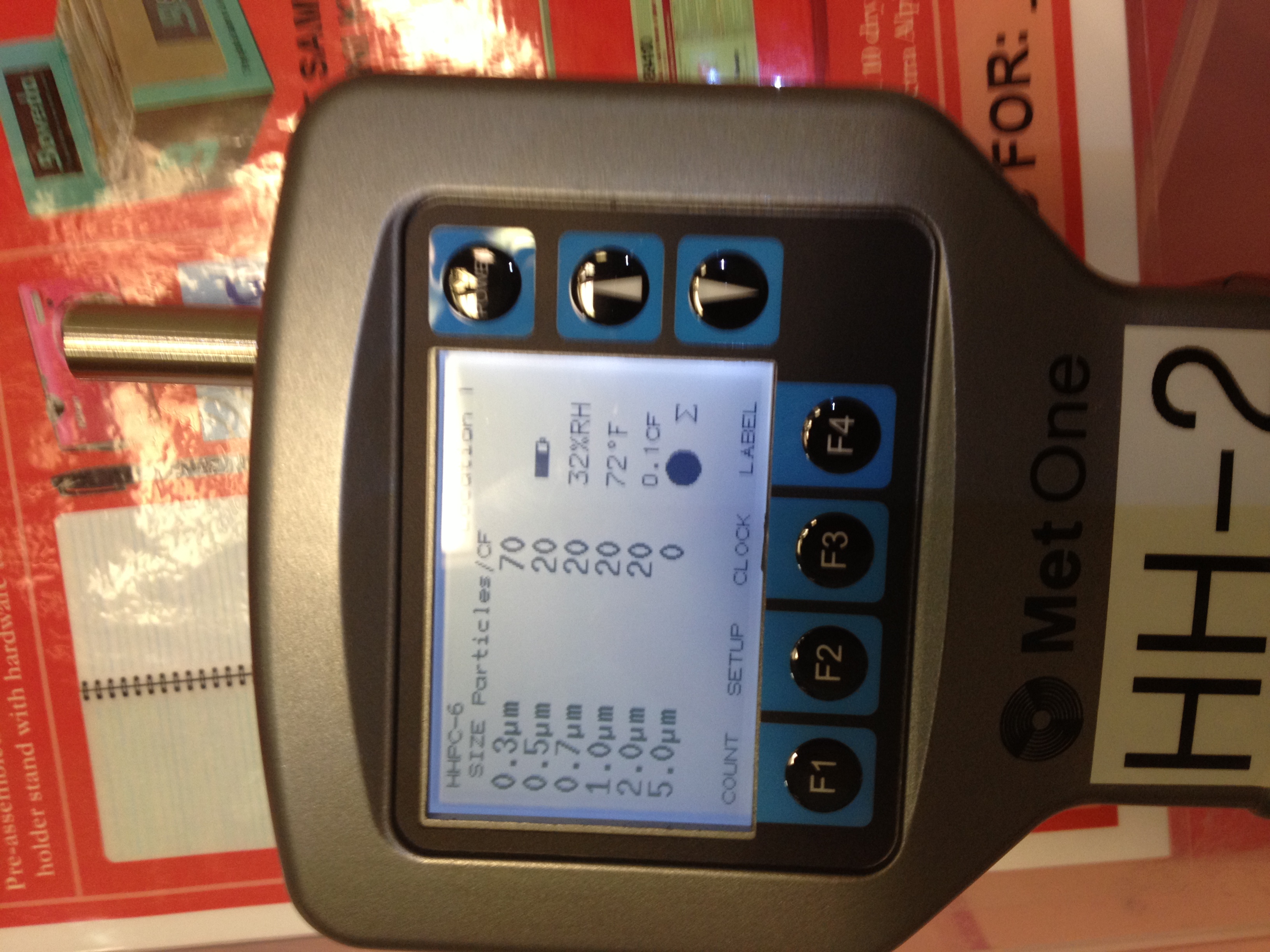
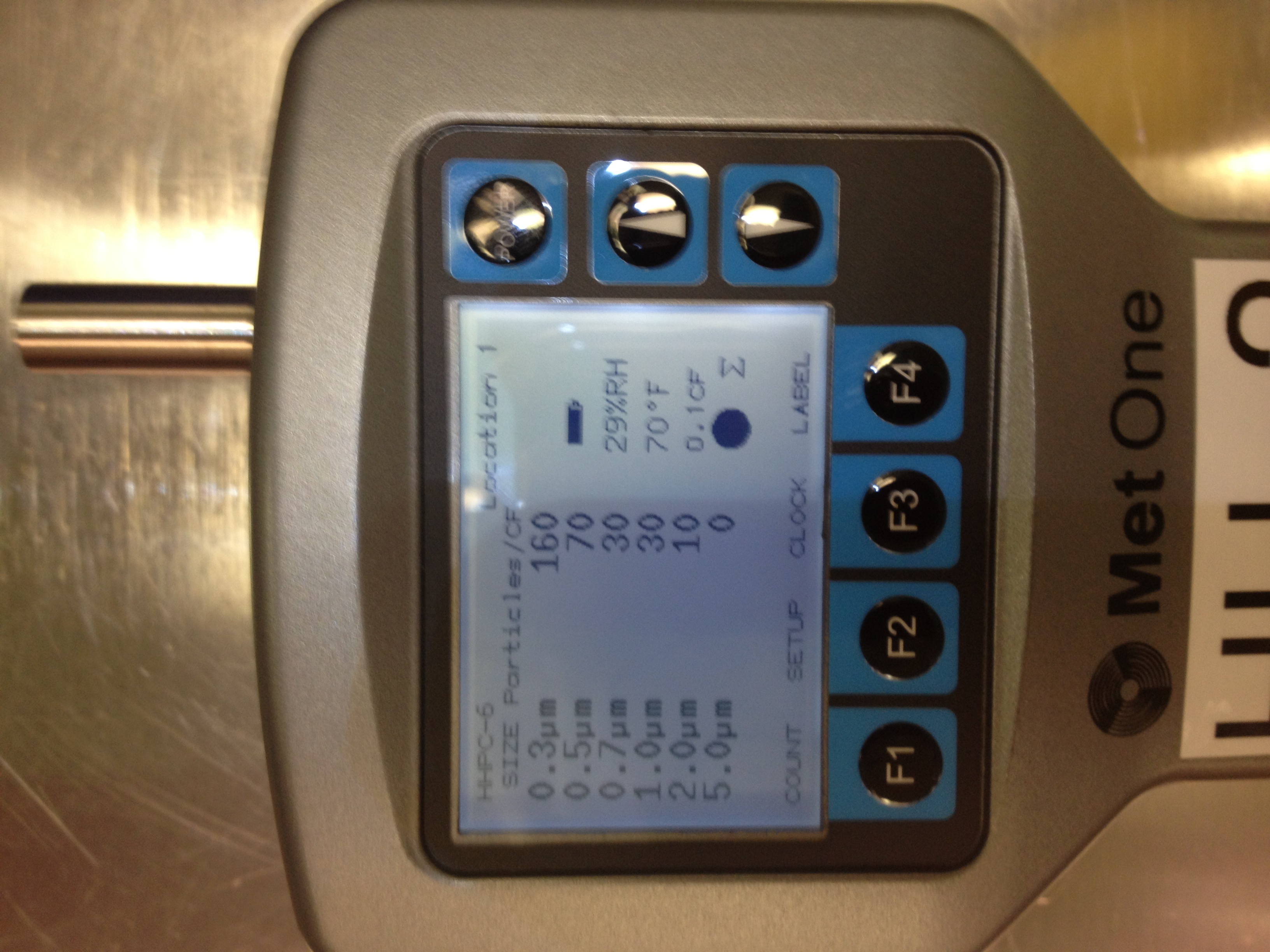
Pics attached if people interested in RH/temp
Focus of tomorrow is to try to finish HAM4 and HAM5, maybe finish BSC3 and BSC2 first contacting, and do some more work in HAM2. See how we go


No surprise,
According to the weather station at PASCO airport (KPSC) the relative humidity on Sunday ranged from 71% at 5am to 21% at 6pm.
The indoor humidity is influenced by the outdoor humidity and temperature.
Inside a chamber the air near a door is a mixture of purge air and LVEA air. The purge air is nominally 0% RH but the LVEA has been ranging between 20 and 40 recently. In addition those water molecules are moving way faster than the purge air and are very happy to move upstream.