jim.warner@LIGO.ORG - posted 16:30, Tuesday 22 April 2014 (11513)
HAM5 ISI TF's running on OPSWS0
No touching.
No touching.
- PSL went down today and Sheila brought it back up, diffracted power is a bit low in the ISS.

- Sheila to ISCT1 to work on cameras 9:00 AM PT

- Fil to EX and EY 9:10 AM PT

- Richard and Peter to EY to work on ESD 9:15 AM PT

- TCS Aussie Crew: Aidan, Matt, David working on CO2X and CO2Y tables, turning on laser.

- Mark(Apollo) going to EX and EY to look for tools 11:15 AM PT

- Gerardo and Mark Barton to H2 PSL Enclosure

- Corey to HAM6 bay to turn on laser for camera work

- Ken running conduit from CO2X table to H1 chiller pods

- Apollo breaking bolts at HAM5&6, Jeff Bartlett taking dust counts, temporarily disabling dust monitor 15

- Hugo updating MEDM screens remotely from Stanford

- Jonathan working on OS upgrade on SVN and Bugzilla

- Filaberto working on output stages of the ETM UIM coil drivers.

- Guardian machine reboot, IMC remained locked in that time during entire reboot and came back in a locked state!

- Cleared HEPI L4C stat monitors.
Scott, and I finished what we could of the actuator sub assemblies. There are a few parts that are currently MIA that will effect the last unit.

After lunch Jim and Hugh came to the rescue and aided with the installation of unit 2's horizontal GS-13's.
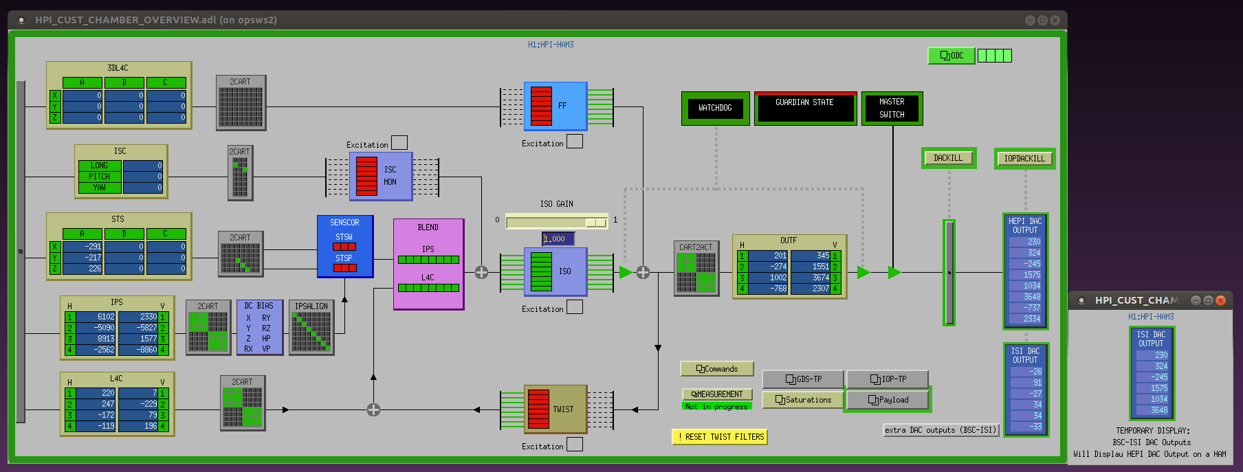
The HEPI overview screens were not displaying the ISI DAC outputs correctly. This was fixed on the HEPI overview screen template, and the update was ported here at LHO.
The update required to add the ISI_DAC macro substitution to the macro substitution text files of HEPI, which was done too. The new version of those files was committed to the svn -r7772
Details about the content of the update can be found in SEI aLOG #453
Work was performed under WP 4588, which can now be closed.
I removed 1,647 SUS channels from the conlog include file. These channels were unmonitored and assumed to no longer exist after model changes. I regenerated the conlog pv_list using this updated include list.

The channel counts are now:
all: 118787
monitored: 118787
unmonitored: 0
We are redefining what the EPICS audible alarm system, reducing it to only include alarms which are not accessible via other data channels and which need URGENT operator/staff attention. To this end I have removed the CDS and PSL alarms from the operator alarm station. This leaves the VACUUM, FMCS, DUST and SOFTWARE_WATCHDOG alarms in place. I had re-worked the Software Watchdog alarms last week to remove duplicate and spurious reporting of these alarms.
Coupled with this is the requirement that urgent alarms also send text messages to cell phones to cover times when the operator is not on duty.
Daniel would like non-urgent alarms to be reported by a new system which filters the data before presenting it to the operator. Currently alarm status is available on MEDM screens which the operator checks regularly.
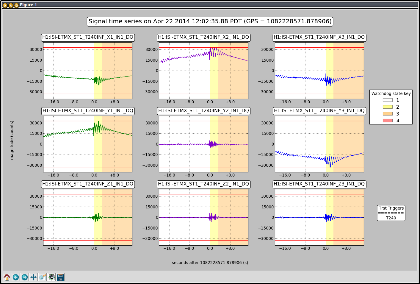
We had ETMX running Tcrappy and sensor correction. We don't know why it tripped.
Now I will put it back to Tbetter with sensor correction because the microseism has come back down.
I noticed that the fiber polarization (in wrong pol) at EY had drifted back up to 32%. The normal procedure for this is to turn the controller back on and adjust the settings; this never seemed to disturb anything. When I turned the controller on it made a funny noise (it sounded like the waveplates were moving rapidly), and BOTH EX and EY polarizations got drastically worse. I manually adjusted both polarizations, and they are back down now. I turned the box off. I did not want to turn the box back on. Clearly this is not good...

The temperature in the MSR were the polarizer is located is varying a lot more now with the change in weather (and between day/night). As I recall, it's pretty sensitive to temperature changes... and the MSR isn't really temperature controlled to a high degree of accuracy beyond 'not hot'.
Did another initial y-arm alignment from scratch.

- TMS pointing to hit the center of ITMY, with the hitting-catch-at-all-four-cardinal-directions technique (Pitch -107.0, Yaw: -25)
- ITMY pointo to the Baffle PD's:
   BPD 1:  Pitch: 197.0, Yaw -157.5
   BPD 4:  Pitch: 230.7, Yaw -191.5
   Center: Pitch: 213.85,Yaw -174.5
- EMTY pointing to center, with the hitting-catch-at-all-four-cardinal-directions technique (Pitch -107.7, Yaw: -34.1)

- This brought back good flashes at the center of the reference camera, without any move of the BS or PR3.
As mentioned in alog 11488, I had pulled the ALS EY REFL common mode board. I have modified the second boost stage so that it is the same as the first (pole at 100 Hz and a zero at 1 kHz). The serial number is SN S1102632. In detial:
The board is now back in the rack and the TFs look good.
This is a tabletop photodetector interface (D1002932-V5, S1103811) in ISCTEY that was misbehaving yesterday. I opened it and found this.
None of the power connectors for Thorlabs PDs and BBPDs were soldered to the board. And one of the connectors was loose (right-most one in the video). See how the legs move as I wiggle.
It's a miracle that it worked at some point. I soldered all of the connectors.
(If avi doesn't play, try mov file, though the time of the mov file seems to be out of whack.)
I opend and checked two randomly selected "Table-Top" boxes (D1002932-v4) from the twelve boxes in Mid-Y storage, serial numbers S1103796 and S1103810, for quality of build and found them to be in good shape. The front circuit card was soldered onto the panel connectors. All screws and fasteners were tight. The general quality of work looked good. Let's hope the box Keita found (S1103811) was an oversight.
I've rebooted h1guardian0 as a requested test to see if it recovers gracefully after a restart, which it appears to do. Also, I took the opportunity to configure the IPMI management port during the reboot. Note that when I logged in to reboot the machine, there were 20 zombie processes reported. That's probably not great since it was just rebooted yesterday.
The Apollo crew was breaking loose the bolts at the septum between HAM 5 and HAM6 to prepare for the upcoming HAM5 installation work. Monitored the dust counts before and during the work on the bolts. Before work started the dust counts in the cleanroom were zero. During the loosing process counts were in the 40 to 60 range while the bolts were actually being turned. Shortly after the wrench work stopped the counts dropped back to zero. I saw no counts over 100 0.3 micron particles during the monitoring; larger particle counts were generally less than the 0.3 micron counts.
I am about to start upgrading drivers on the DAQ as specified in WP4583. There will be NO DATA recorded during the period when the data concentrator is rebooted - as it is due for a full FSCK at boot, this will be a period of 10-15 minutes. For the remaining system upgrades, there will be intermittent access to the recorded data as those systems (h1nds1, h1fw1, h1broadcast0) are rebooted. Changes to h1nds0 and h1fw0 will happen at a later time. Further updates will be posted to this entry with specific downtime.
DAQ Downtime Report
h1dc0: 16:07:40 - 16:18:00 UTC There is NO data recorded by the DAQ during this period.
h1nds1: 16:26:00 - 16:28:20 UTC
h1fw1: 16:33:55 - 16:55:50 UTC There is NO data available via h1nds1/h1fw1 for this period. Use h1nds0/h1fw0 for frames ending/starting in this timeframe.
h1broadcast0: 17:06:55 - 17:16:00 UTC
Most installs were uneventful. However, on h1fw1, the MTU was not set to 9000 in /etc/conf.d/net as it is on h1fw0, which prevented daqd from running after restart. I changed /etc/conf.d/net to match and rebooted to fix; I have no idea how it ever worked before. On h1broadcast0, I disabled the items in local.start that are only useful for a data concentrator; h1broadcast0 being a clone of a data concentrator had these unnecessary additions.
Technical Details
(l inadvertently left these out of the original entry)
The change is to upgrade the Myricom ethernet adapter drivers for the DAQ broadcast network to version 1.5.3.p3, compiling them with the MYRI10GE_ALLOC_ORDER=2 option and using the big_rxring firmware at driver load. This is to attempt to reduce the number of dropped frames that are seen occasionally, most often on the framewriters, that also trigger 'retransmission request' errors in the daqd log. And additionally, on the data concentrator to make use of the MYRI10GE_THROTTLE option to see if tuning the packet emission rate has any effect for the receiving systems. The primary method of measuring any change is to use the SNMP monitoring of the DAQ broadcast switch to monitor the dropped/paused frames per host port. The same changes on the test stand indicate some improvement.
Things were working fine till 9:00 AM PT, then the PSL shut off due to a chiller error. Sheila was notified of this. When the PSL comes back online, I'll append its status with a comment.
This is Thomas
Sheila turned the laser back on, she thinks the chiller may have caused the trip, but it didn't need re-filling.

- Laser is ON
- Output power = 27.5 W
- Watchdog is RED
- PSL SYSSTAT.adl is all green

- PMC just came back online
- PMC Reflected power at 1.4 W and Transmission at 10.0 W

- Ref Cav just came online
- Camera looks ok and trans PD threshold is at .75

- ISS is at 6.58% diffracted power
- Just came back online.
Aidan. Matt. Dave H.
The CO2X laser was energized and aligned to the initial polarizer and AOM. The AOM was energized (the external RF input and power appear to work successfully) and set to maximum modulation depth. The AOM was aligned to the Bragg angle to maximize the diffraction efficiency (this has yet to be measured).
The cable connecting the voltage and current monitor channels from the laser power supply to the ADC had to be rewired as the I_MON and GND pins were back to front.

