J. Kissel, for S. Dwyer, J. Rollins, D. Barker, A. Pele, J. Batch, H. Radkins, D. Sigg, K. Kawabe, S. Ballmer
Several things went down at the same time during my melee with the front-ends yesterday (see LHO aLOG 11464), with little indication of the problem, which gave us a proper Monday morning adventure.
After much digging we think we've uncovered the time-line of how things went bad:
(1) 2014-04-20 18:51 UTC (Sunday, 11:51 PDT) Kissel requests IMC Guardian to enter DOWN state, MC REFL Camera loses signal. Unclear what this did, but the guardian does not touch any alignment signals #foreshadowing. This is very shortly after I post the "I'm getting started" LHO aLOG 11463.
(2) 2014-04-20 20:40 UTC (Sunday, 01:40p PDT) After two successful front-end model install/restarts (PR3 and MC1), the install/restart of MC3 causes h1sush2a front-end computer's IOP throws a FIFO error. This results in the familiar error that drive appears to come out of the user model, but does not get past the IOP out to the real world. (see LHO aLOGs 7385, 8424, 8964)
(3) 2014-04-20 21:38 UTC (Sunday, 02:38p PDT) The guardian computer crashes because it ran out of memory. This rendered all guardians non-functional.
Fixes (in chronological order):
(A) (for 2) 2014-04-21 16:45-17:00 UTC (Monday, 09:45a-10:00a PDT) all h1sush2a user models (h1susmc1, h1susmc3, h1susprm, h1suspr3) killed, h1iopsush2a restarted, all models started
(B) (for 3) 2014-04-21 16:50-18:00 UTC (Monday, 09:50a-11:00a PDT), Jim physically reboots guardian machine, Jamie logs in remotely and fixes things.
(C) (for 1) 2014-04-21 18:25-19:00 UTC (Monday, 01:25p-02:00p PDT) Fix (2) and (3), and *realign MC WFS path* to regain WFS centering and good camera shot.
Detailed Commentary:
(A,2) The FIFO error (2) is frustrating, not only because I still haven't put the error indicator on the SUS screens (totally my fault, accepted), but also because the error indication itself is indicative of two different things:
- When a USER DACKILL has said "I'm in a bad state, ignore the DAC outputs from my model."
- When the IOP throws a FIFO error.
Maybe other things of which I don't know, as well.
This is bad because, although hopefully now much more rare, the USER DACKILL trips whenever the USER watchdogs trip to ensure that no drive signal gets out of the USER model's domain. This connection between USER watchdogs and USER DACKILLs was established in the overly-cautious time after the 2012 fiber break, when we weren't sure that stopping the last output (i.e. what the user watchdog does) actually stopped the drive. Perhaps it's time to just remove this layer...
(B,3) The only information I have about the guardian failure is what you see in LHO aLOG 11470. Hopefully Jamie can give a more complete report in the coming days.
(C) We have NO IDEA why the MC REFL path had changed. Note that Stefan recalls a similar incident in February (see LHO aLOG 10335).
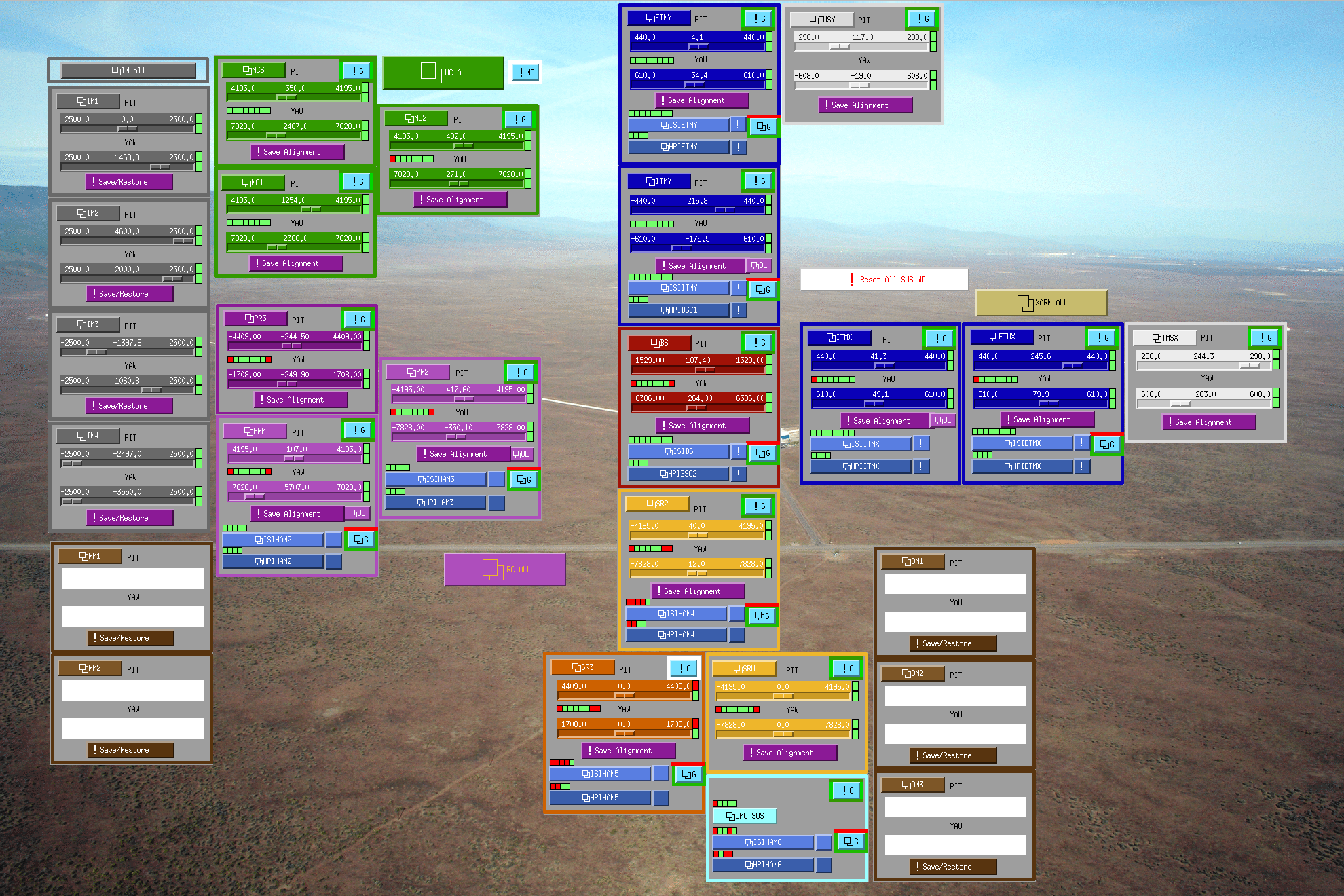
Once we recovered the MC SUS drive, and guardians re-aligned SUS and HEPIs, we spend the usual hour or two convincing ourselves that every drivable object was in the same place:
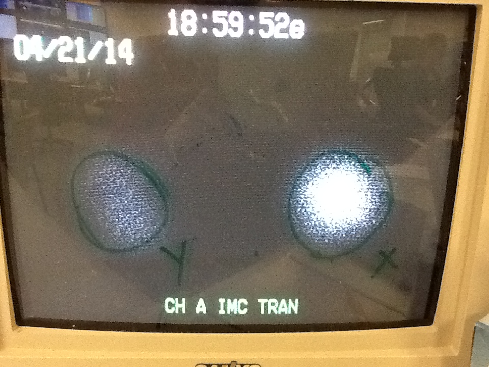
- The TRANS path showed good behavior. The transmitted light from the mode cleaner looks as it did before, H1:IMC-TRANS_OUTPUT is ~3800 [ct], H1:IMC-IM4_TRANS_SUM_OUTPUT is ~25 [ct], and the splotch on the IMC TRANS camera looks centered and the same.
- Moving around the PSL PZT only decreases the TRANS signal, indicating that the input pointing is still good.
- SUS are in the same place. All bottom stage OSEMs showed the same locations as before, alignment sliders had correct offsets in place, MC WFS offload values were roughly the same (and small compared to the offsets).
- HEPI were in the same place. Aside from trends of the CPS on both HEPIs and ISIs, we slowly translated HEPI in X and Y, which moved BOTH REFL and TRANS camera signals, indicating the REFL change is not common to both signals.
- Sheila locked up the X arm to get a straight-shot to PR3, which bounces off of PR3, through PR2, then back to HAM1 and onto ISCT1. Since the beam is large on PR3, its also quite sensitive to HAM2's alignment. The green remained aligned on PDs in ISCT1.
Given that there's *no* active steering between MC1 and the REFL WFS / Camera, we just don't understand how a reboot of any computer would change this paths alignment. The best theory is that there's a loose optic in the path on HAM2, which gets jostled during a HEPI / ISI trip/reboot. Conscious of shaking more important things, I always ramp down the control and offsets the ISIs and HEPIs before doing model restarts, but ... like I said, it's all we've got.
Sarah would be proud.


DAQ Downtime Report
h1dc0: 16:07:40 - 16:18:00 UTC There is NO data recorded by the DAQ during this period.
h1nds1: 16:26:00 - 16:28:20 UTC
h1fw1: 16:33:55 - 16:55:50 UTC There is NO data available via h1nds1/h1fw1 for this period. Use h1nds0/h1fw0 for frames ending/starting in this timeframe.
h1broadcast0: 17:06:55 - 17:16:00 UTC
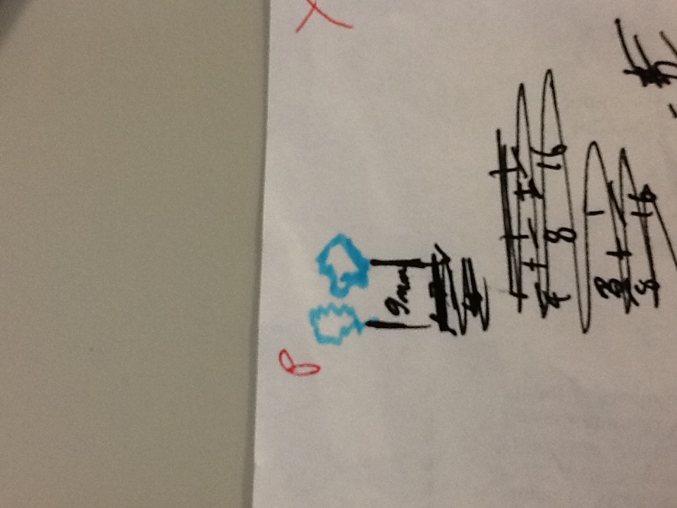
Most installs were uneventful. However, on h1fw1, the MTU was not set to 9000 in /etc/conf.d/net as it is on h1fw0, which prevented daqd from running after restart. I changed /etc/conf.d/net to match and rebooted to fix; I have no idea how it ever worked before. On h1broadcast0, I disabled the items in local.start that are only useful for a data concentrator; h1broadcast0 being a clone of a data concentrator had these unnecessary additions.
Technical Details
(l inadvertently left these out of the original entry)
The change is to upgrade the Myricom ethernet adapter drivers for the DAQ broadcast network to version 1.5.3.p3, compiling them with the MYRI10GE_ALLOC_ORDER=2 option and using the big_rxring firmware at driver load. This is to attempt to reduce the number of dropped frames that are seen occasionally, most often on the framewriters, that also trigger 'retransmission request' errors in the daqd log. And additionally, on the data concentrator to make use of the MYRI10GE_THROTTLE option to see if tuning the packet emission rate has any effect for the receiving systems. The primary method of measuring any change is to use the SNMP monitoring of the DAQ broadcast switch to monitor the dropped/paused frames per host port. The same changes on the test stand indicate some improvement.