arnaud.pele@LIGO.ORG - posted 09:38, Friday 18 April 2014 - last comment - 17:05, Friday 18 April 2014(11432)
HEPI Position Control or fluid flow appears to NOT contribute to ETMY ~10hz Resonance
Arnaud & Hugh
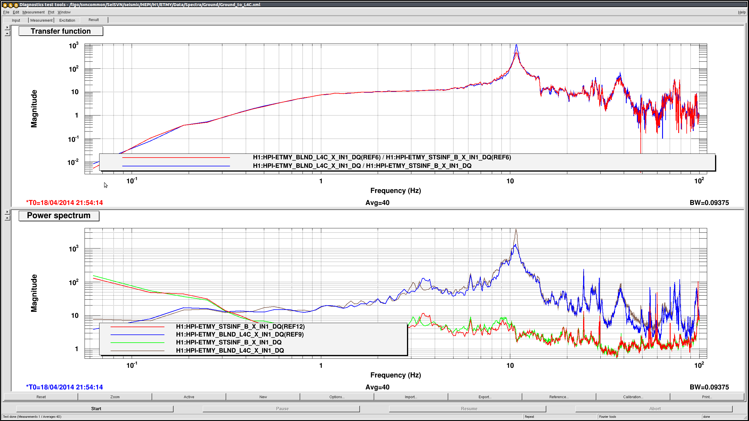
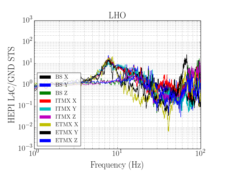
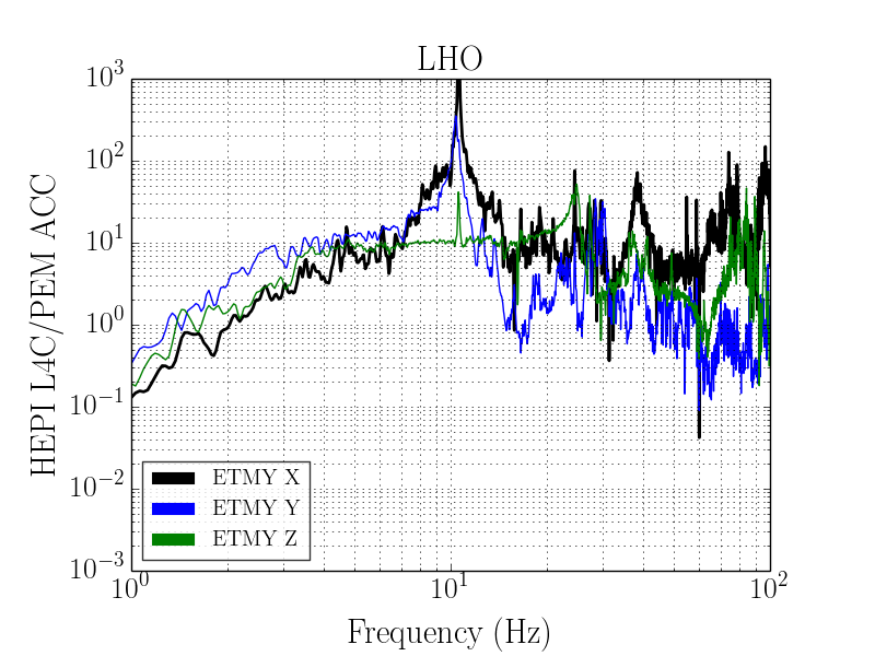
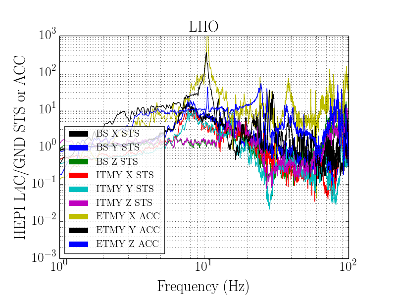
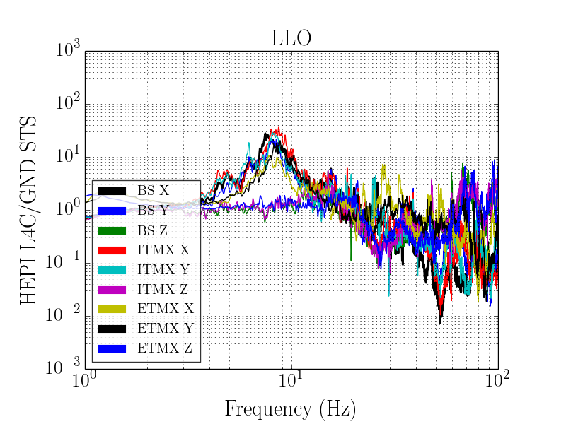
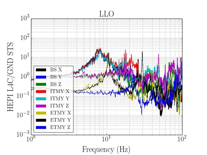
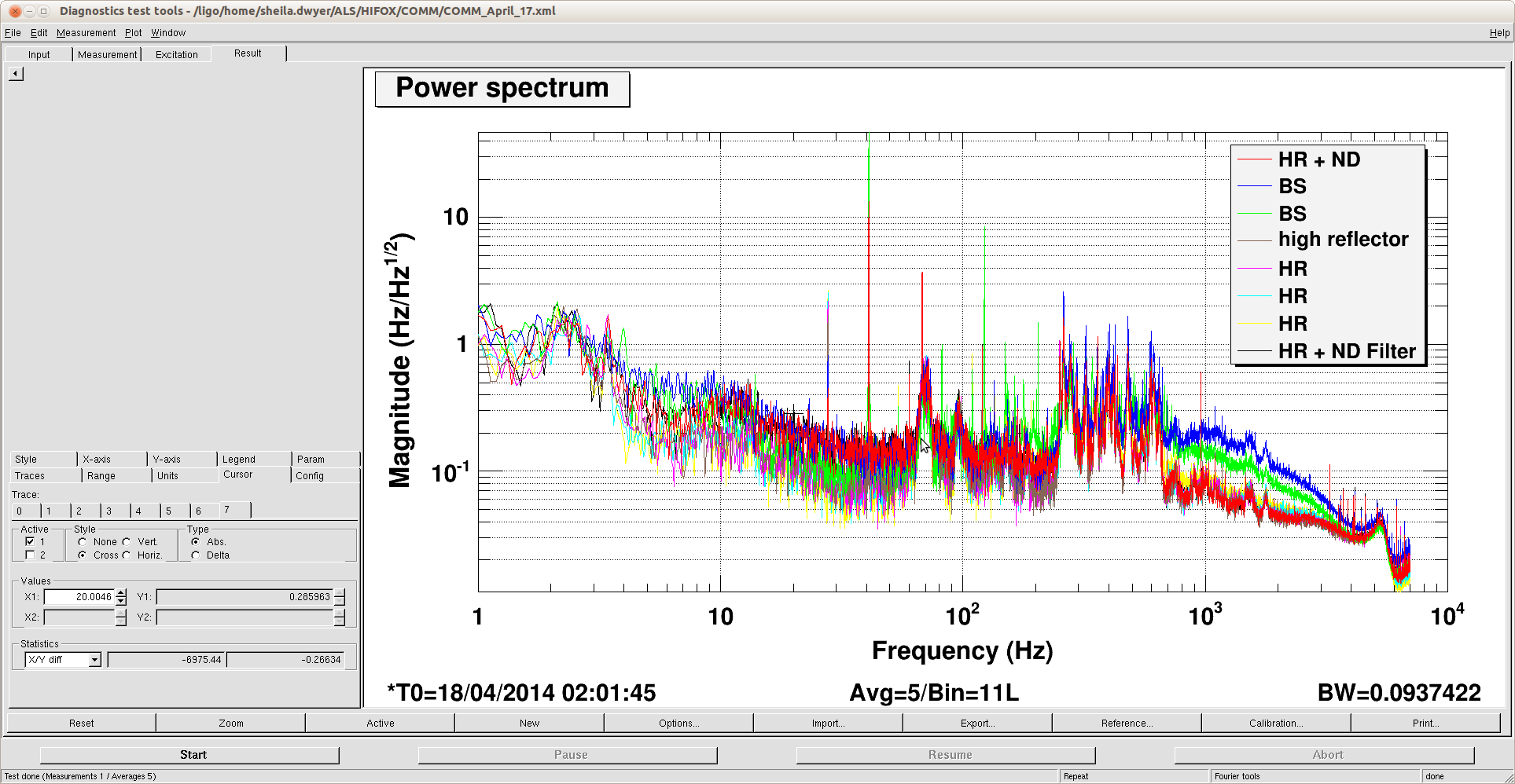
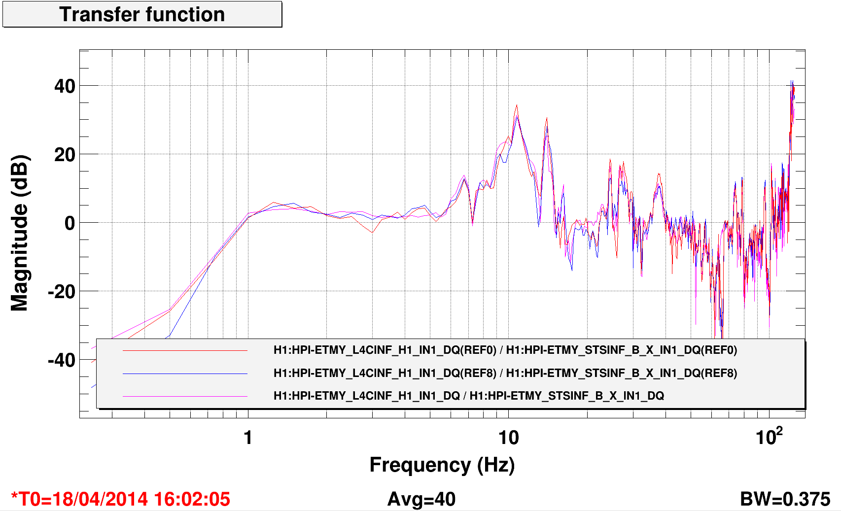
We quickly looked at this. We didn't expect an effect but HEPI PS control runs at ~10hz (Epics) and we could check so we did. The attached looks at the Pier top horizontals over the ground STS2. All the horizontsl HEPI signals looked the same wrt both horizontals of the STS2s. First Ref is ISI OFF, HEPI position loop ON, Second Ref is ISI OFF, HEPI Position Loop OFF, current trace is with the fluid flow zeroed. No affect evident.
Images attached to this report
Comments related to this report
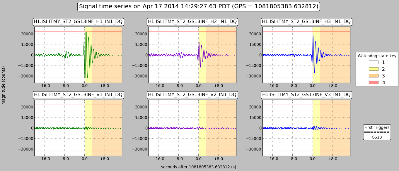
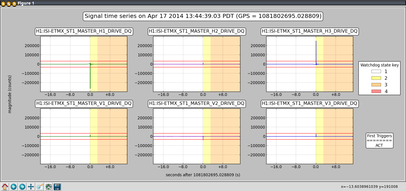
I guess I was wrong. After taking a closer look at it, closing the position loops on HEPI is actually amplifying the motion at 10Hz, by a factor of ~3. References are with position loop off.
Images attached to this comment