Looking at the REFL baffle will tell me if our current alignment is sufficient to get the REFL beam from the first surface of PRM into HAM1. When I looked at the beam before, it was slightly clipped on the East side of the aperture of the baffle, so misaligned in yaw. I have no knowledge of the alignment state of PRM at the time I saw this clipping. When I have the beam back and a locked IMC, I'll be able to evaluate the REFL/PRM alignment. FYI - there is currently a yellow viewport cover without stickers on the East HAM2 door - this is not an invitation to remove the viewport cover without a work permit or contacting the Control Room! I will either switch the viewport cover to one that has stickers, or get the proper stickers for this cover, before we open the PSL shutter.
The area between HAM4 and the high bay/LEA roll-up door was cleared in preparation for the ISI install. The BSC ISI storage container was flown from that area to the North Bay. First cleaning was done on HAM4 and its cleanroom (yesterday). The HAM storage container was moved away from HAM4's north side and the bolts were loosened on the south door. Second cleaning will take place ASAP.
Sorry for the double entry. The submit button stuck...
The area between HAM4 and the high bay/LEA roll-up door was cleared in preparation for the ISI install. The BSC ISI storage container was flown from that area to the North Bay. First cleaning was done on HAM4 and its cleanroom (yesterday). The HAM storage container was moved away from HAM4's north side and the bolts were loosened on the south door. Second cleaning will take place ASAP.
The forklift was flown into the West Bay so that SEI could use it for adding mass to the ISI.
Raised HIGH alarms to 85 deg F ops@operator0:~ 0$ caput H0:FMC-MY_AH_COOLTEMP_2_DEGF.HIGH 85 Old : H0:FMC-MY_AH_COOLTEMP_2_DEGF.HIGH 75 New : H0:FMC-MY_AH_COOLTEMP_2_DEGF.HIGH 85 ops@operator0:~ 0$ caput H0:FMC-MY_AH_COOLTEMP_1_DEGF.HIGH 85 Old : H0:FMC-MY_AH_COOLTEMP_1_DEGF.HIGH 75 New : H0:FMC-MY_AH_COOLTEMP_1_DEGF.HIGH 85 ops@operator0:~ 0$ caput H0:FMC-MX_AH_COOLTEMP_1_DEGF.HIGH 85 Old : H0:FMC-MX_AH_COOLTEMP_1_DEGF.HIGH 80 New : H0:FMC-MX_AH_COOLTEMP_1_DEGF.HIGH 85 ops@operator0:~ 0$ caput H0:FMC-MX_AH_COOLTEMP_2_DEGF.HIGH 85 Old : H0:FMC-MX_AH_COOLTEMP_2_DEGF.HIGH 80 New : H0:FMC-MX_AH_COOLTEMP_2_DEGF.HIGH 85 ops@operator0:~ 0$ caput H0:FMC-MY_VEA_202A_DEGF.HIGH 85 Old : H0:FMC-MY_VEA_202A_DEGF.HIGH 75 New : H0:FMC-MY_VEA_202A_DEGF.HIGH 85 ops@operator0:~ 0$ caput H0:FMC-MY_VEA_202B_DEGF.HIGH 85 Old : H0:FMC-MY_VEA_202B_DEGF.HIGH 75 New : H0:FMC-MY_VEA_202B_DEGF.HIGH 85 ops@operator0:~ 0$ caput H0:FMC-MY_VEA_202C_DEGF.HIGH 85 Old : H0:FMC-MY_VEA_202C_DEGF.HIGH 75 New : H0:FMC-MY_VEA_202C_DEGF.HIGH 85 ops@operator0:~ 0$ caput H0:FMC-MY_VEA_202D_DEGF.HIGH 85 Old : H0:FMC-MY_VEA_202D_DEGF.HIGH 75 New : H0:FMC-MY_VEA_202D_DEGF.HIGH 85 ops@operator0:~ 0$ caput H0:FMC-MX_VEA_202A_DEGF.HIGH 85 Old : H0:FMC-MX_VEA_202A_DEGF.HIGH 75 New : H0:FMC-MX_VEA_202A_DEGF.HIGH 85 ops@operator0:~ 0$ caput H0:FMC-MX_VEA_202B_DEGF.HIGH 85 Old : H0:FMC-MX_VEA_202B_DEGF.HIGH 75 New : H0:FMC-MX_VEA_202B_DEGF.HIGH 85 ops@operator0:~ 0$ caput H0:FMC-MX_VEA_202C_DEGF.HIGH 85 Old : H0:FMC-MX_VEA_202C_DEGF.HIGH 75 New : H0:FMC-MX_VEA_202C_DEGF.HIGH 85 ops@operator0:~ 0$ caput H0:FMC-MX_VEA_202D_DEGF.HIGH 85 Old : H0:FMC-MX_VEA_202D_DEGF.HIGH 75 New : H0:FMC-MX_VEA_202D_DEGF.HIGH 85
Light pipe installed for IOT2L's Mode Cleaner Transmitted path (and no blood was spilled---be sure to wear gloves when handling this ducting!).
Added stdenv.py to /ligo/cdscfg and stddir.py to /ligo/cdscfg/lho, at the request of Hugo.
Attached are plots of dust counts > .3 microns and > .5 microns in particles per cubic foot requested from 5 PM May 13 to 5 PM May 14. Also attached are plots of the modes to show when they were running/acquiring data.
Pier Interface Chassis S1202914 had Inductive Capacitive Sensor(KAMAN)SN S0812221-06-04 replaced due to railing outputs. New Inductive Capacitive Sensor was installed SN S0812221-06-22. Old unit is being sent back to manufacturer. F. Clara -
Dave B., Patrick T. This work falls under permit number 3887. This morning I installed new EPICS IOC code for the weather stations in /ligo/apps/linux-x86_64/epics-3.14.12.2_long_sc. The module code is davis_weather_monitor_ii-1.0.0 and the IOC code is weather_davis_weather_monitor_ii-1.0.0. The targets are in /ligo/lho/h0/target. The IOCs are running in screen on h0epics2. This was done primarily to change the channel names to reflect the aLIGO PEM standard in T1200221-v5. I also hard coded the alarm severities for the wind speeds in the database files. The wind speed alarm levels are set by hand and stored in the autoBurt.req files. The macro substituted database files are now generated from a template and substitutions files when the IOC is compiled. An iocBoot directory named ioch0_weather_cs was created and the target named h0weatherms was changed to h0weathercs. Dave renamed the minute trend files to reflect the channel name changes. his alog entry New medm screens were linked to in the site map that incorporated the channel name changes. The autoBurt.req files were updated.
The mapping for the channel name changes is attached.
(Caveat: Since the alignment was not really touched up, alignment fluctuation might be coming into play. Wait for WFS commissioning for a better data.)
Jan Pold asked and here it is.
1 Watt into MC. The transmission is monitored with IM4 transmission QPD as well as MC2 transmission QPD.
The whitening gain for both of the QPDs were 18dB (though I could have set it higher I don't think that would have made any difference).
Three stages of whitening filters were used for both: For MC2, it is a fixed one stage (0.4:40) plus two stages of switchable (1:10), and for IM4 since the fixed stage was not present I used all three switchable stages.
60Hz comb filter was turned off.
The input to each segment before dewhitening was 1000 to 6000 counts (mostly AC), so it's decent.
The beam was not centered at all: For MC2, [P,Y]=[0.14, 0.55], and for IM4 this was [0.22, 0.07].
Anyway, the spectrum was measured for SUM_IN1_DQ channel, divided by DC and plotted. The data was saved as
/ligo/home/controls/keita.kawabe/RIN
ISS status:
Digital loop on, first loop on, second loop off.
PD B was used.
PSL-ISS_GAIN 9.6dB.
Diffraction 13 to 16%.
It turned out that HVAC was/is blasting full. We'll try science mode -ish HVAC with Robert at some stage.
Yesterday I swapped the PDA100A that was used as a monitor for the IR power on the ALS table for one of the SMAPD1As. Currently there are 65 mW in the IR path before the PBS and 0.91 mW incident on the PD. That means the splitter ratio, which will depend on the half wave plate, is 1.4% now and responsivity is 0.36 A/W, which might be low because the PD might not be well aligned. I also double checked the calibration of the fiber transmission PDs, they are OK within 15%. I also saw that there was no beat note because the beams were badly misaligned. After tuning up the alignment I saw 300mV pp (-9dBm) after the 13dBm amplifier.
[Cheryl, Chris, Kiwamu]
This morning we have prepared a calcite polarizer (SN#2) which will be installed in the IMC_REFL path on IOT2L. Right now it is put aside out of the main path and will be installed tomorrow.
And we installed the calcite later yesterday (Tuesday). It seems working fine -- it creates P and S polarizing beams as expected. We also installed a HWP in front of it to allow us to adjust the amount of S-polarization propagating through the calcite.
It was responding very slowly, making it hard to even move the mouse around the screen. Restarting did not fix the problem, which is also present on the corner machine. If I use a mac instead of one of the control room machines, it works fine. Also, several control room machines are no longer running the terminal server client. They just say there was an error launching the application, operator1, opsws0 and opsws1
Patrick set up the remmina remote desktop on the ubuntu 12 machines, those are usable now.
15 days of pumping is shown in the attached plot.
Several annuli remain to be pumped down.
HAM1, HAM2 - since HAM 1 is vented this annulus system(HAM1/HAM2) cannot be evacuated. Provided there are no big leaks this should be ok.
HAM 4 septum - liikewise HAM4 is vented so the septum annulus cannot be evacuated. Same comment as above - ok but not optimum.
BSC1, 2, 3 not yet evacuated.
A comparison of the pumpdown curve for the yend and the LVEA which both have a full test mass chamber assembly give the following pressure vs time dependences on the assumption of a 1/t water emission law: 2.3 x 10^-5 LVEA P(tdays) = ----------- torr t(days) 5.0 x 10^-6 Yend P(tdays) = ----------- torr t(days) The pumping speed ratio for water and hydrocarbons becomes F(LVEA) -------- ~ 1/4 F(Yend)
The LVEA volume includes one ITM/ISI assembly, one BSC/ISI assembly, and two HAM ISI assemblies with all their optics and cabling. HAM1 is NOT part of this volume due to the septum in place.
ENDY has the one ETM/ISI assembly.
I and Cheryl went to the floor, MC was locked, and PRM was aligned so the IFO REFL is centered on the baffle hole before HAM1.
New "aligned" value for PRM alignment slider is [P,Y]=[-730, 0] urad.
This used to be [-830, -50] in air, the change is quite small considering the fact that we're under vacuum now.
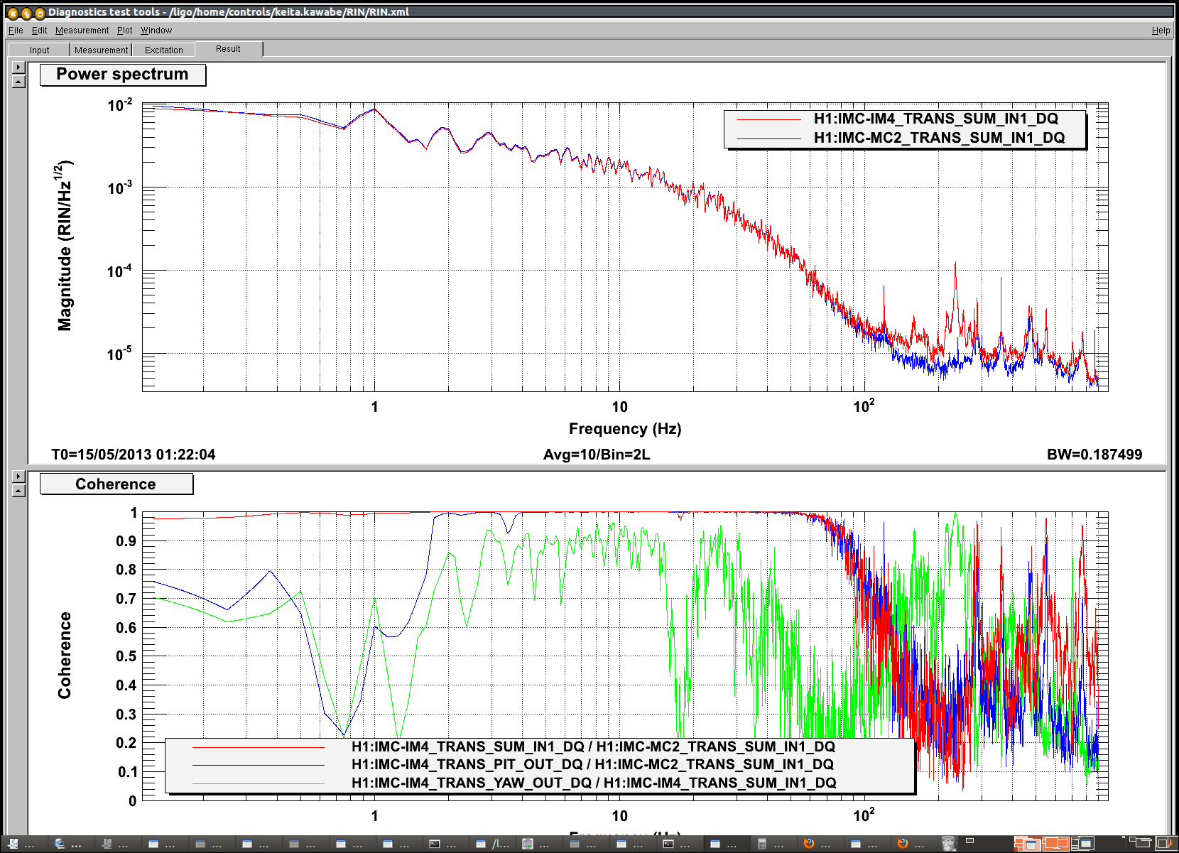
With this data even the most serious skeptic should agree that the IO alignment is OK. We should proceed to center IM4 and MC2 trans QPDs because they're quite off-center now.