JimW and I worked on getting the performance of BSC-EY comparable to the performance of BSC-EX, before handing off to SUS.
BSC-EY now has the following control tools installed:
-
Blend filters: Start, T750mHz, TCrappy, TBetter
-
Isolation loops: Lv1, Lv3
-
Tilt Decoupling: GND-ST1
-
Sensor correction: gains need to be tweaked.
We compared the performance of BSC-EY with the performance of BSC-EX, with both platforms under BSC-EX's most used configuration:
-
Blend filters: TBetter
-
Isolation loops: Lv3
-
Tilt Decoupling: GND-ST1
-
Sensor correction: off
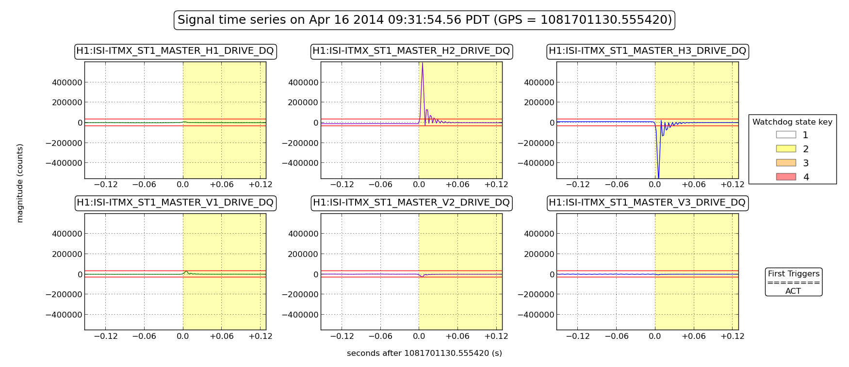
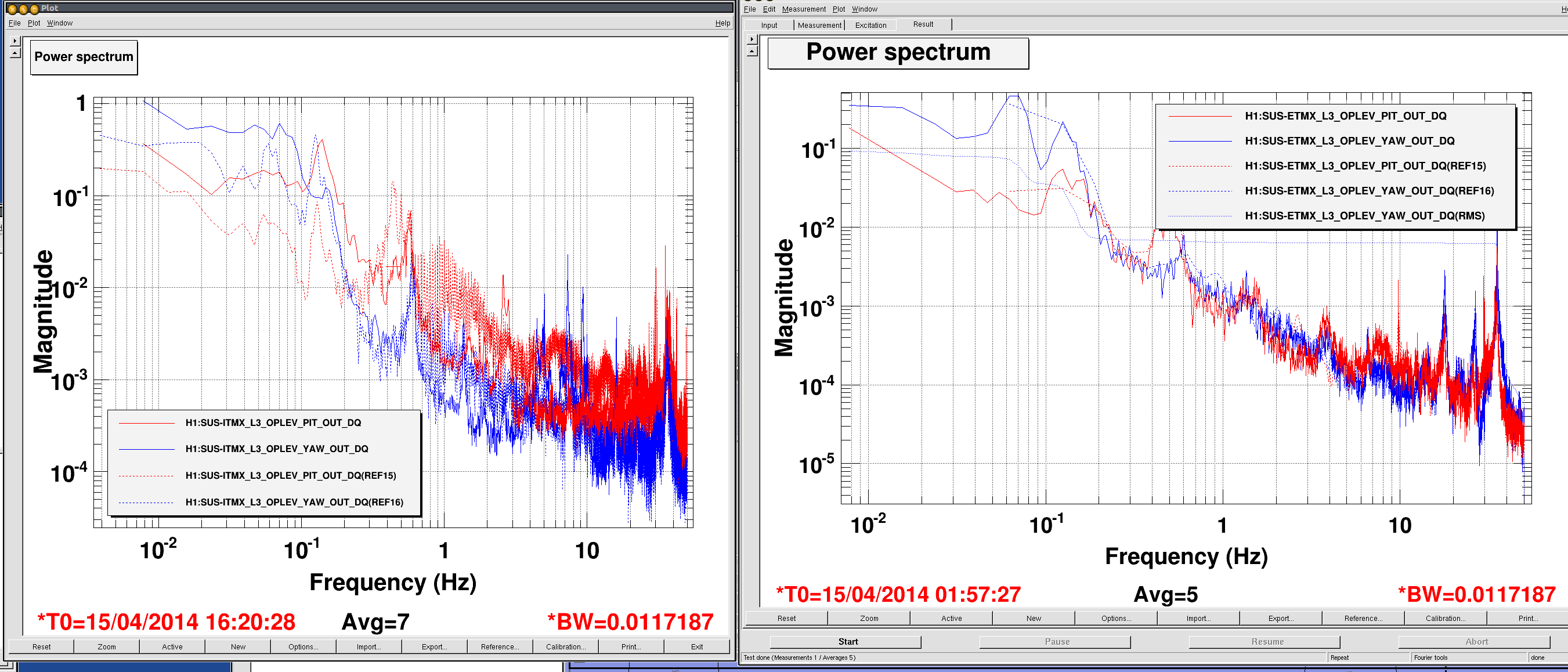
Attached Plots show comparable performance of the ISIs, at the projected suspension point, for similar ground motion at both end stations. (plots calibrated in nm and nrad).
One can notice a 10Hz peak, on BSC-EY spectra. We went ahead and took performance spectra at EY with the Isolation off. The peak is also there when the isolation and damping loops are off. Hence, the peak seen at 10Hz is neither caused, nor amplified, by the ISI active controls.
Since SUS provides plenty of isolation at 10Hz, we decided to give them the go ahead to start their testing.
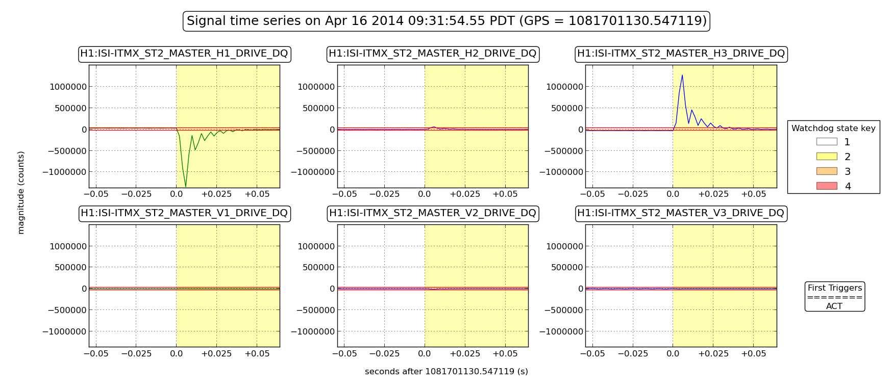
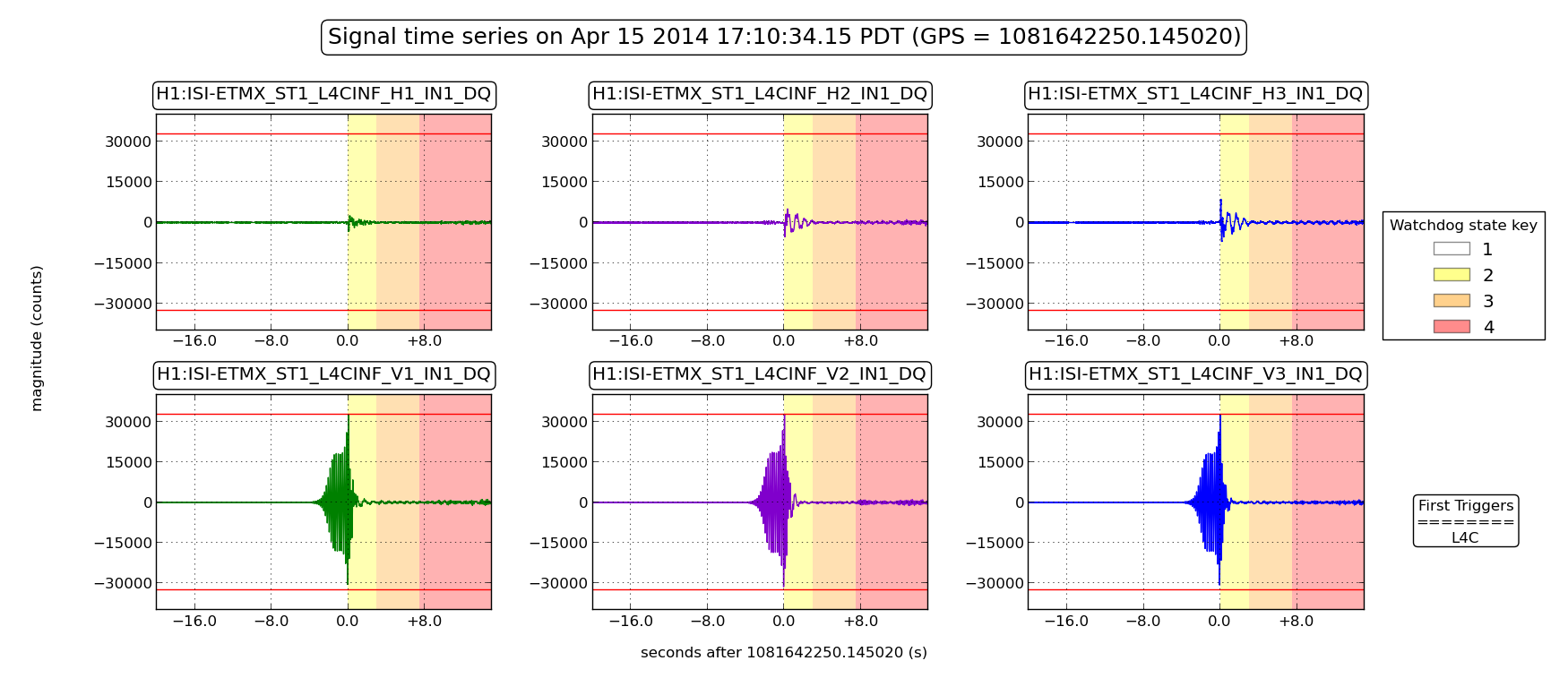
Meanwhile, JimW and I kept investigating. We noticed that HEPI L4Cs were seeing the 10Hz peak too, and that it is mostly seen on the vertical L4Cs (see Page 1 of last attachment). We were able to reduce this peak's amplitude by a factor of ~10 by simply turning HEPI position loops off (see Page 2 of last attachment). It looks like HEPI-EY position loops are somehow amplifying the 10Hz peak, but they are not its source, as the peak still appears clearly with HEPI off.


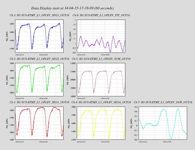
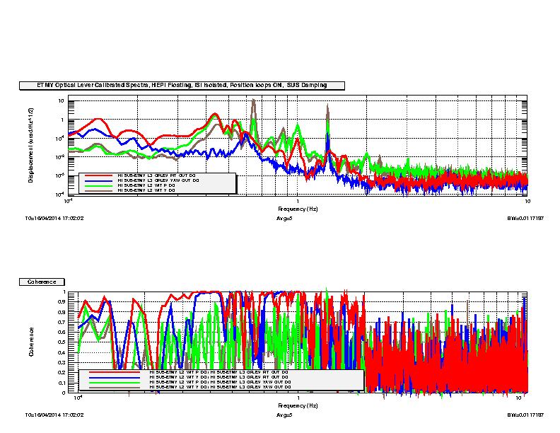
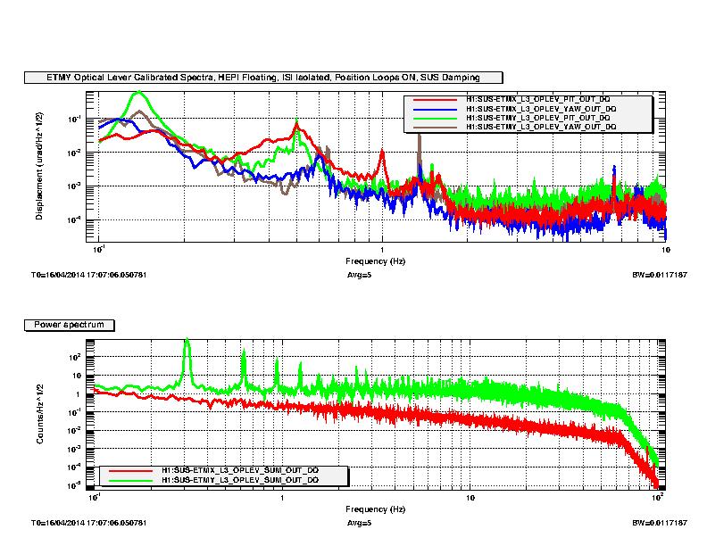