stefan.ballmer@LIGO.ORG - posted 15:21, Sunday 23 March 2014 - last comment - 08:38, Tuesday 25 March 2014(10944)
POBAIR_B_RF18 demod fuse tripped / sign for REFLAIR flipped ....
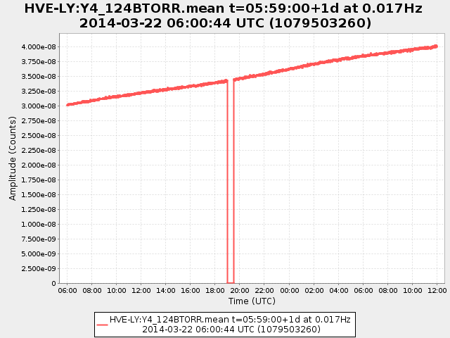
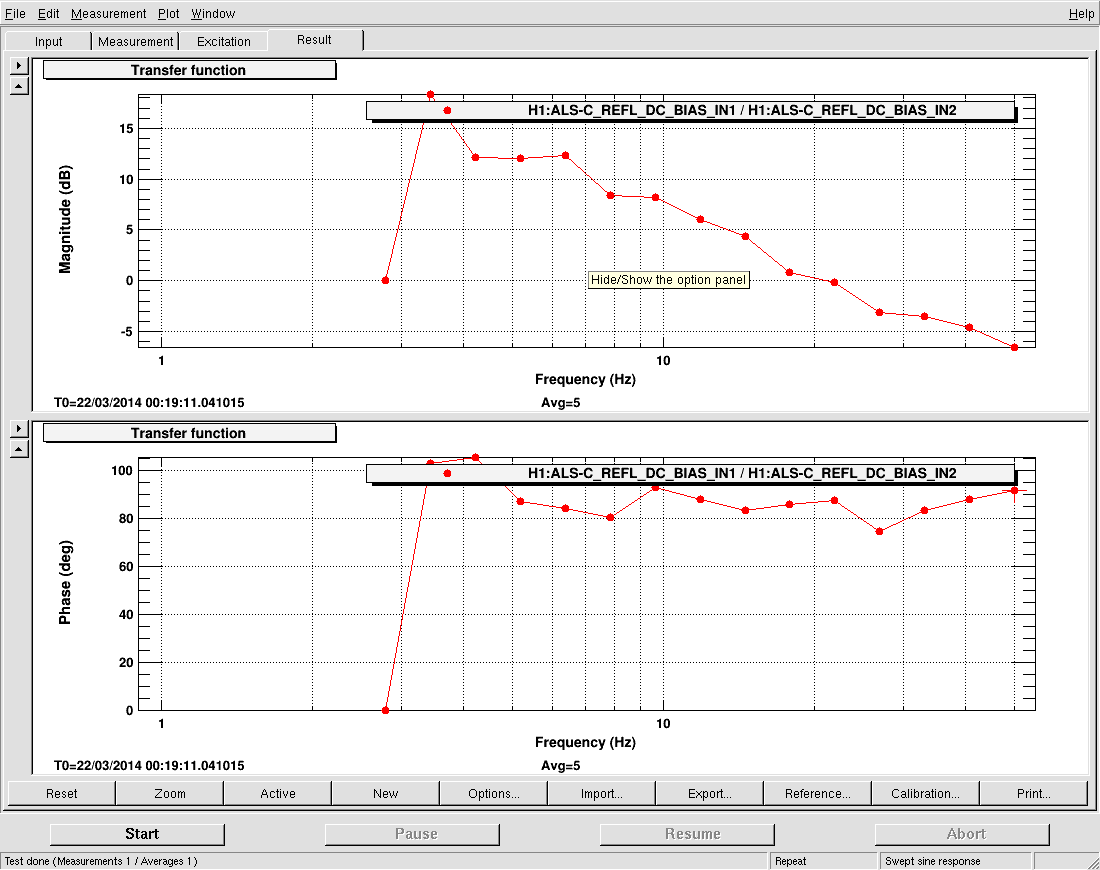
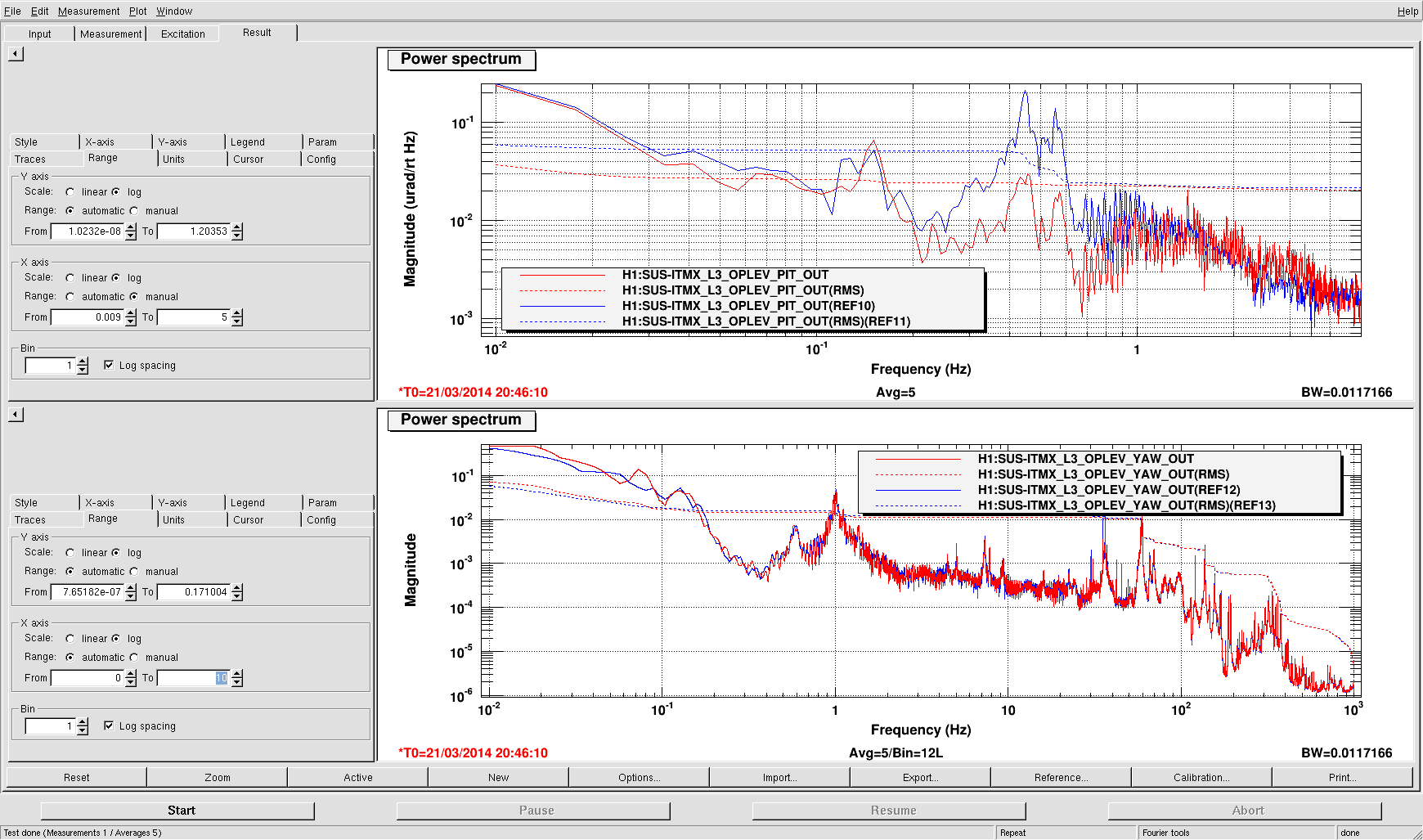
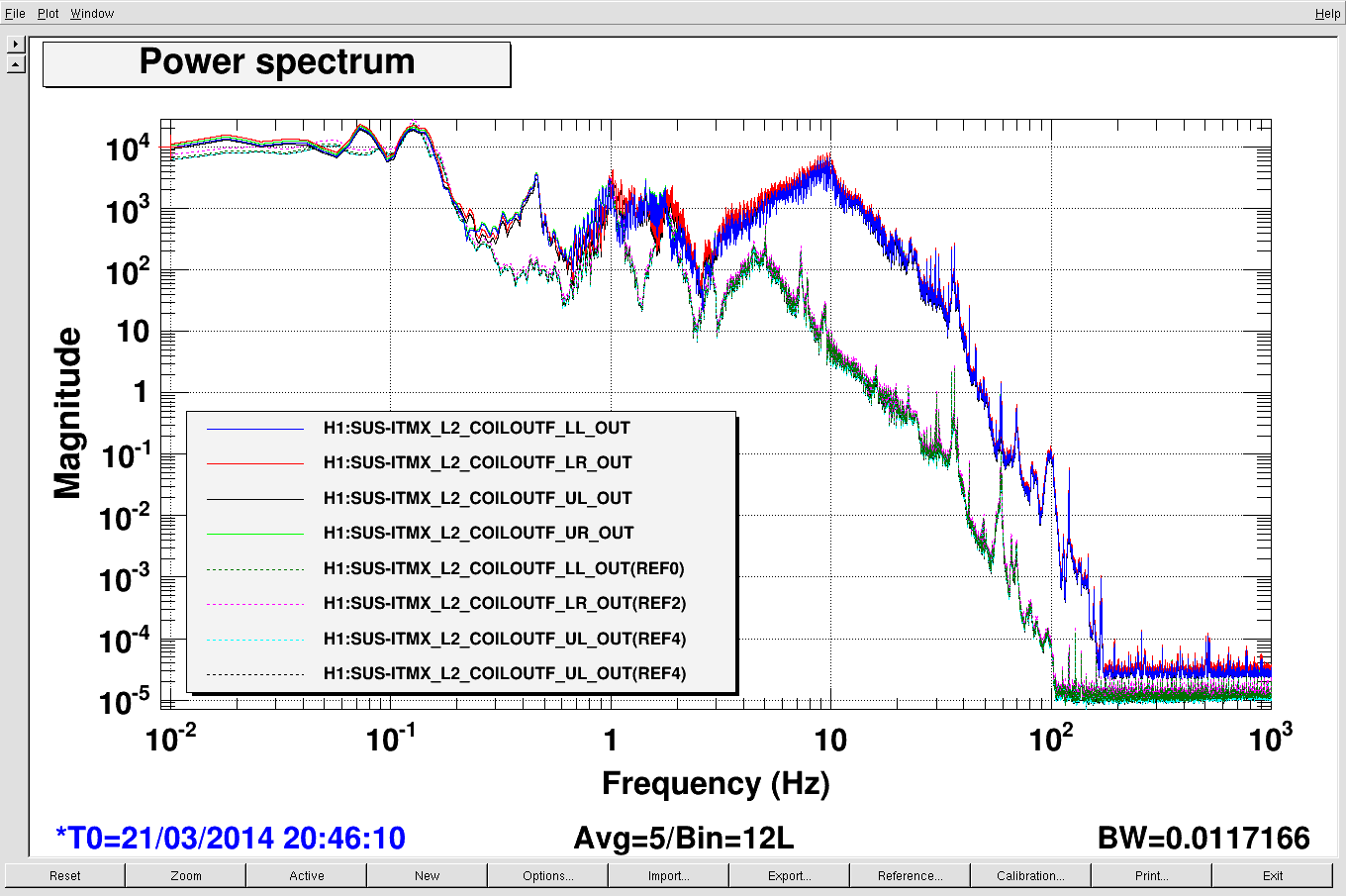
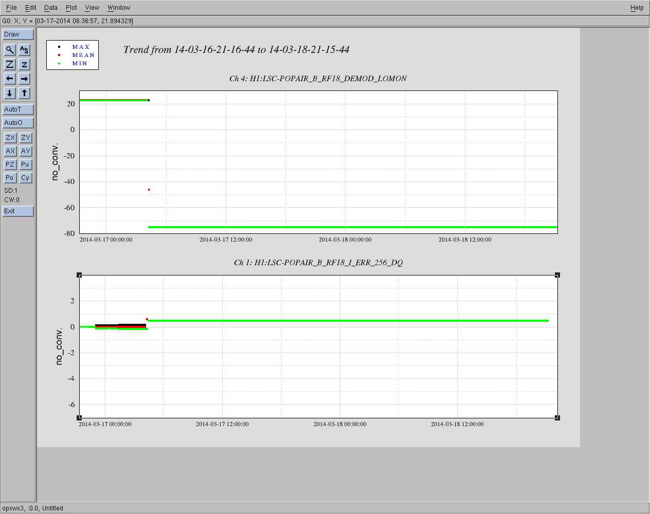
Dave O, Stefan

While attempting to lock the PRC we noticed that POB_Air_B_RF_I_Err was low on signal. We traced this back to a low de-mod signal (see attached plot). We traced this down to a tripped fused in the ISC_R2_Rack. This tripped on the 17th March. We tried to reset it but it simply re-tripped again.

When we locked PRX and PRY, we were also surprised that we needed to flip the feed-back sign in PRCL to lock on the carrier (compared to the settings the LSC guardian uses).
Images attached to this report
Comments related to this report
I assume by fuse you guys mean breaker right? I can't tell if this unit is now functional (as might be implied by successful locking mentioned in this post) or still problematic. I would like to understand this better in case it points to a potential flaw somewhere.
The negative regulator had the kapton insulation material under it not the gray that works. The -15 was shorting to the case. We replaced both +-15 insulating material. Unit was restored and is functional.
Unit D0902796 Serial Number S1000977 had insulation for both positive and negative regulators replaced.