Rolf, Jeff, Ben, Dave
Rolf added the susHWWD part to the h1susitmy model, which permits the front end to remotely reset the hardware watchdog and set the operational parameters (trip levels and time-to-trip). Communication is acheived via a single binary output channel from SUS ITMY.
We tested the binary I/O communication lines in both directions. The readback was tested by removing one or both of the 37pin connectors on the HWWD (from the Satellite Amp monitor port) which simulates a loss of LED current. The readback was not initially received by the model, but started working after the cable was reseated. We tested the control function by remotely resetting the watchdog and changing the time-to-trip from the defaut of 20mins to 2mins.
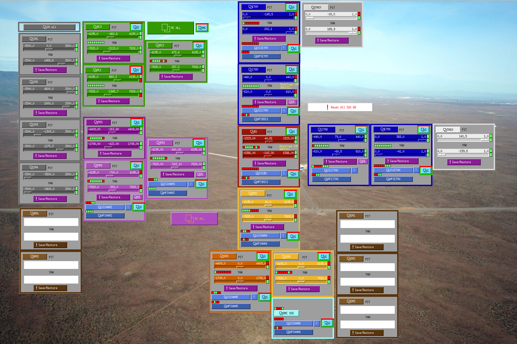
New MEDM screens have been built. An alarm handler was also built.
The running h1susitmy model has been built against the trunk (as of 9th January) to permit the new HWWD part to be used. I have subsequently reset the rtscore/release pointer back to RCG2.8.2
After lunch Jeff will put the ITMY SUS and SEI through a series of tests to verify the watchdog functions correctly.