greg.grabeel@LIGO.ORG - posted 15:35, Saturday 02 November 2013 (8363)
Mirror cleaning
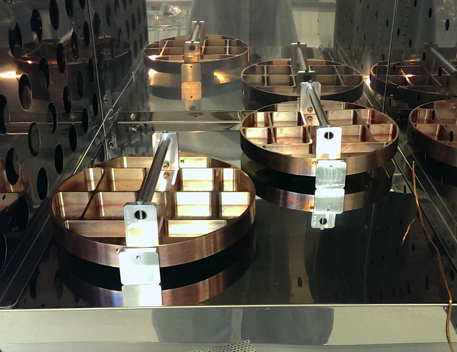
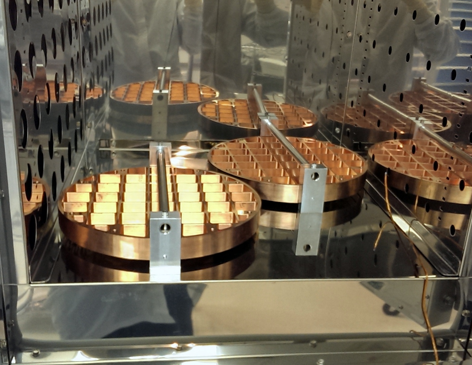
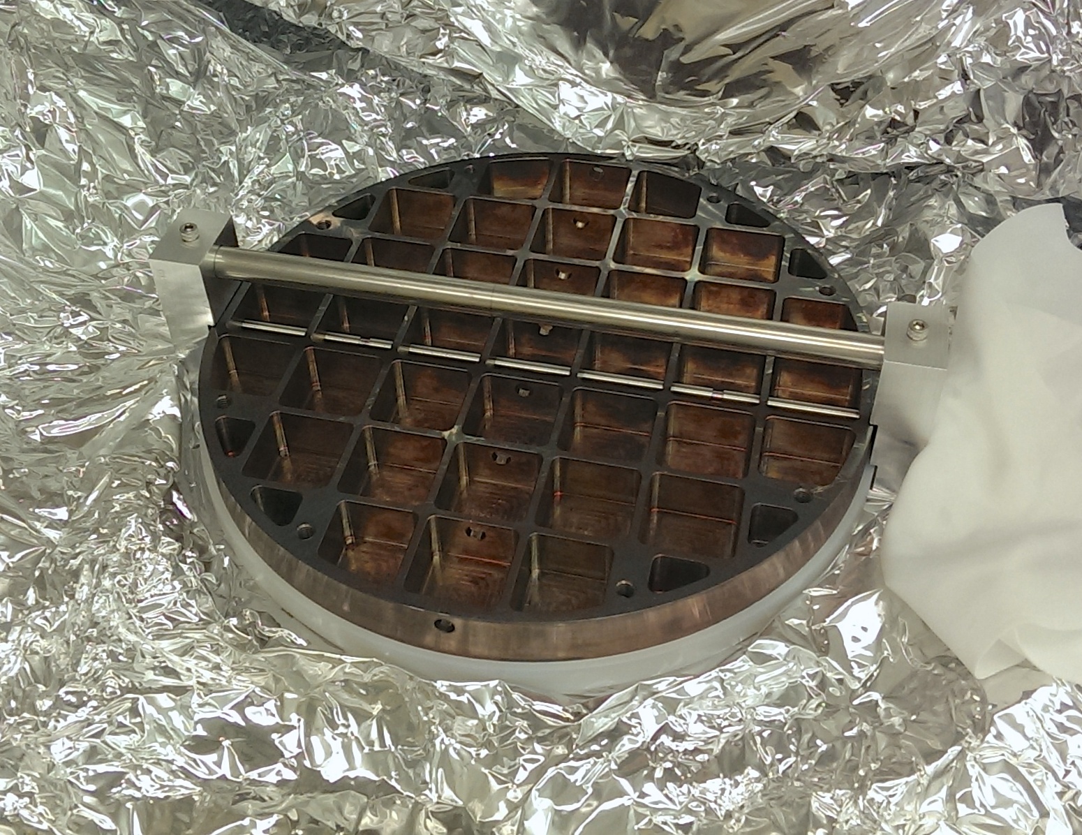
Chris S. Joe D. Greg G.

With the help of Joe and Chris the SM1 mirrors (SN 3,4) were cleaned and are air-baking now, they should be done Monday evening. The SM2 mirrors were also completed recently and are wrapped and bagged and ready for install.
Images attached to this report