S. Dwyer, J. Kissel, D. Barker [with help from R. Savage, P. King, D. Feldbaum, and K. Thorne by phone]
Since Sheila was the only cognizant PSL operator on site, and I wanted to learn, I followed her around as she made attempts to bring the PSL back up from yesterday's power outtage. As of ~2:00p PT (21:00 UTC), the PSL is now running in the following state:
- Low Power (32.1 W NPRO "front end" output power)
- FSS on, ISS off (see details below)
- PSL Enclosure is in "Science Mode" with air conditioning, fans and lights turned way down or off.
The full story:
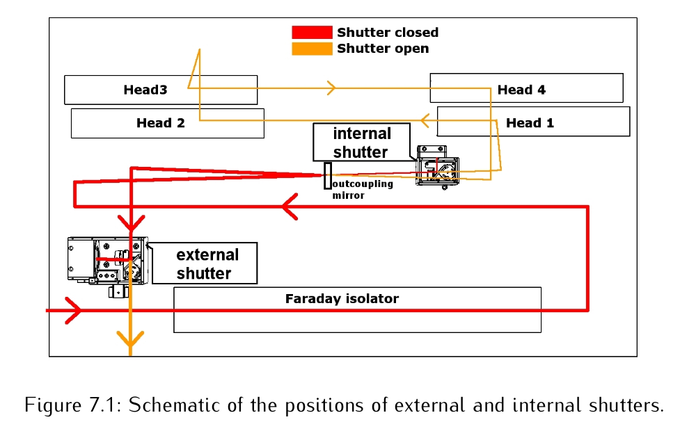
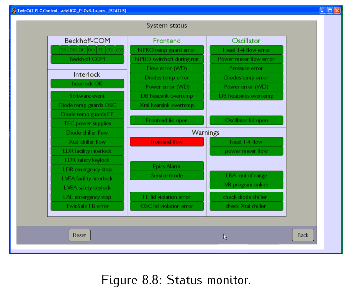
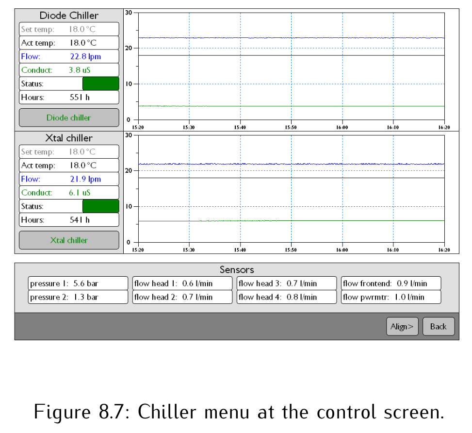
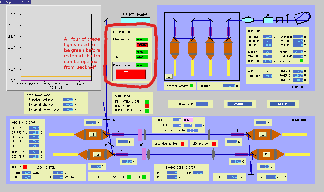
We began with the latest start-up procedure: T1200259. However, after getting through all the steps to turn on the PSL to a low-power state (as advised by Rick -- though we couldn't find an aLOG indicating that it had been left in low power), we had found two error messages left on the STAT sub-screen of the PSL Beckhoff Overview Screen (see T0900641_Figure8p8_PSLStatusScreen.png from pg 54 of T0900641): "EPICS ALARM" and "VB PROGRAM ONLINE" were red. In addition, the DIODE CHILLER (DC) [water] flow rate was a little bit below nominal threshold (> 22.5 [liters per minute]) at 21.8 [lpm] on the the CHIL screen (see T0900641_Figure8p7_ChillerScreen.png from pg 53 of T0900641). In this condition, we also found that the High Power Laser's [HPL's] external shutter would not open from the Beckhoff Overview Screen -- needed regardless of whether you want to run in high- or low- power mode, because this shutter prevents light from continuing on to the Pre-Mode Cleaner (see T0900641_Figure7p1_HPLShutters.png from pg 27 of T0900641.)
After a couple of hours of chasing our tails flipping switches, redoing the procedure, and calling the available experts, David clued us in to a "one line" solution that Keith had put together, which Keith then pointed us to: LLO aLOG 2322, indicating that the H1:PSL-EPICSALARM is the culprit. Regrettably, Keith's network layout and computer configurations are arranged just differently enough that we couldn't use his exact solution. Instead, Dave and I looked for this channel, and found the channel buried in the
${userapps}/opt/rtcds/userapps/trunk/psl/h1/models/h1pslpmc.mdl,
(which was, of course, tough to find because the model is two years old, and still uses the now-defunct pink EzcaRead block, with the full channel name hard-coded at the top level),
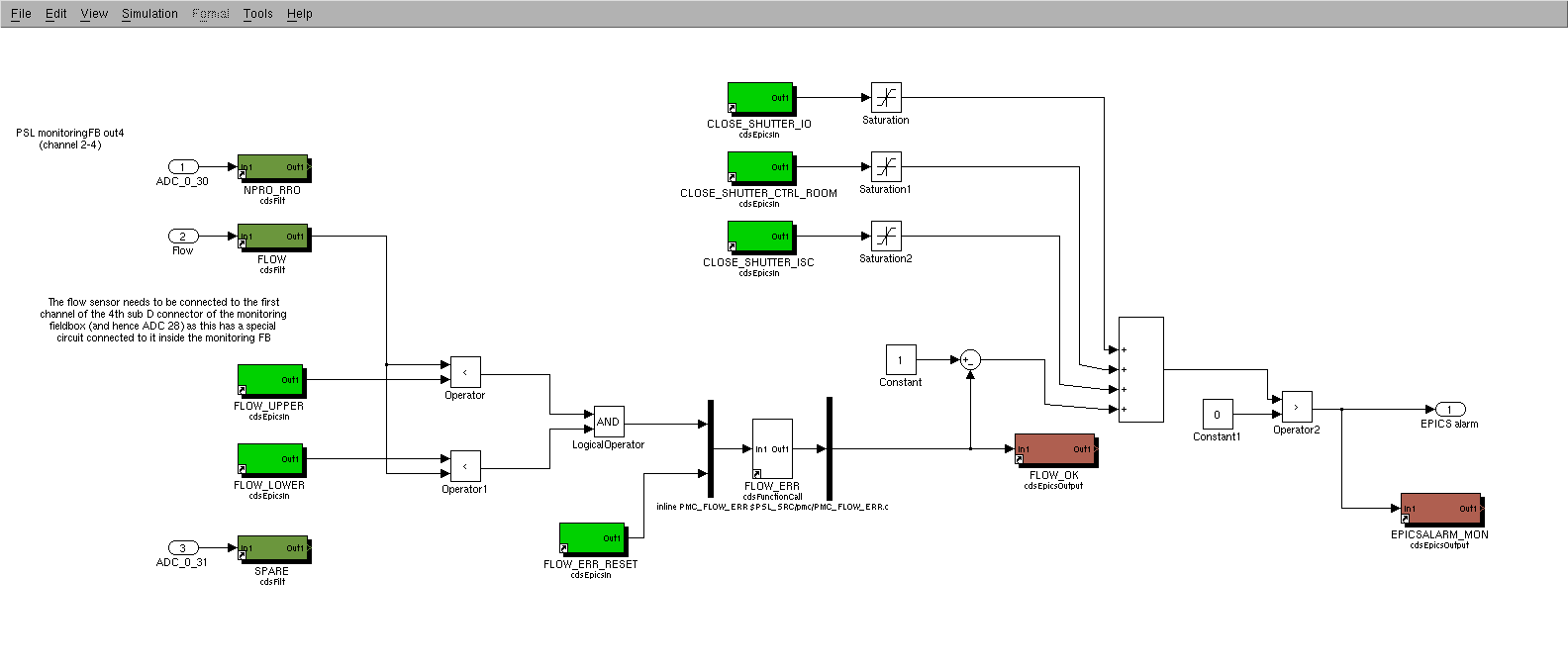
and as Dave mentions, we traced the logic back to a latched flow rate alarm in the MIS sub-block (this inside of which is shown in h1pslpmc_MIS.png). Another interesting point: though the four channels in the front end which control define the H1:PSL-EPICSALARM,
H1:PSL-MIS_FLOW_OK
H1:PSL-MIS_CLOSE_SHUTTER_IO
H1:PSL-MIS_CLOSE_SHUTTER_ISC
H1:PSL-MIS_CLOSE_SHUTTER_CTRL_ROOM
are displayed on the MEDM / EPICS version of the PSL Overview Screen (as seen from the control room, see PSL_OVERVIEW_SCREEN.png), H1:PSL-EPICSALARM is not shown and therefore the link between these EPICS variables and the Beckhoff alarm is unclear. It turns out, as Dave mentioned, only H1:PSL-MIS_FLOW_OK was still red after Sheila and I gave up poking around, so Dave and I queried the threshold and trigger variables "manually" via caget (because they're also not shown on the EPICS or Beckhoff screens) and found the trigger variable comfortably in the range, so we reset it. For future reference,
controls@opsws8:models 1$ caget H1:PSL-MIS_FLOW_INMON
H1:PSL-MIS_FLOW_INMON -5373.77
controls@opsws8:models 0$ caget H1:PSL-MIS_FLOW_UPPER
H1:PSL-MIS_FLOW_UPPER -5000
controls@opsws8:models 0$ caget H1:PSL-MIS_FLOW_LOWER
H1:PSL-MIS_FLOW_LOWER -6000
(Note: these threshold and trigger variables are uncalibrated, so it's unclear how these counts relate to [lpm] shown on the Beckhoff screen.)
As soon as we reset this variable, the STATUS screen started blinking wildly, and we appeared to be back in business as all of the automated loops took over. Nice!
However, we noticed after a few minutes that the reference cavity would not remain locked for more than 10 - 30 seconds. I had assumed this was because the laser still needed to warm up, and there was some sort of mode mismatch and/or thermal issues with the ISS/FSS. After a few hours (telecons) of letting the PSL warm up, we found the reference cavity still blinking in and out of lock. Sheila and I sat down to diagnose, but found ourselves too ignorant of the FSS and ISS to really figure out what the problem was. We simply tried various combinations of switching the autolockers for both ON and OFF, and found that the refcav stayed locked with only the FSS running. Since we just want to get the mode cleaner locked enough for Mark to continue violin mode hunting and for Jamie to play around with Guardian, we figured leaving the ISS off -- until those with further expertise return -- would be just fine.