The beam jitter into the IMC with the PSL in "commissioning mode" was measured. This was done by DC misaligning the IMC in all 4 degrees of freedom (D.O.F.s) separately, and measuring the relative intensity noise (RIN) spectra in IMC transmission at MC2trans QPD and IM4trans QPD. The RIN spectra were calibrated to HG10 mode amplitude in the input beam using the expressions relating cavity eigenmode D.O.F.s to MC mirror D.O.F.s in [1], along with the equations relating transmitted power to misalignment in the presence of an alignment offset and beam jitter which is small compared to the offset.
The results are compared with the requirements for PSL pointing stated in [2] in the first two attached plots. The measured jitter is roughly 1 order of magnitude above the requirements at frequencies greater than a few Hz. This statement comes with a few caveats:
1. The PSL was in "commissioning mode", which is known to be a higher jitter noise environment than the "science mode" (see [3]).
2. Measurements were unfortunately not taken of the RIN in IMC transmission in the nominally perfect alignment state. It's possible therefore that some points on the jitter spectra were limited by 'intrinsic' intensity noise, rather than intensity noise coupled from beam jitter. I will try to get a plot for the intrinsic intensity noise on the same axes in due course.
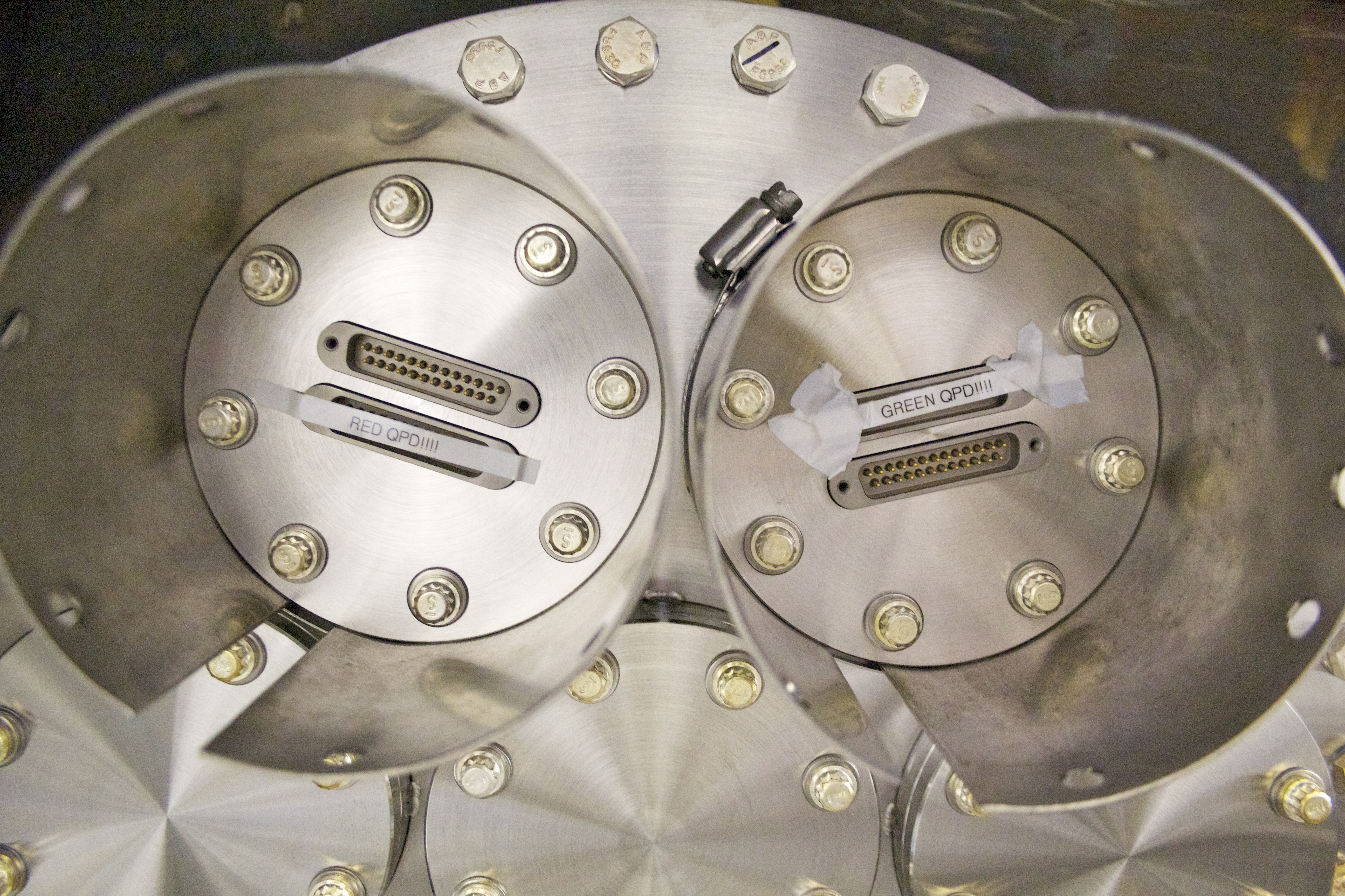
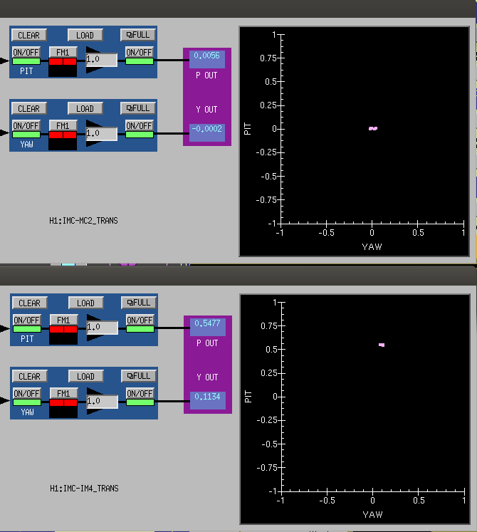
3. Beam centering on the IMC transmission QPDs may have been an issue. The beam on MC2trans QPD was well centered, as expected since this is part of the WFS loop, but the beam on IM4trans QPD was quite high (see attached jpeg of the DC QPD MEDM readouts). For this reason I trust results from MC2trans more, because if there was clipping (as is more likely on IM4trans) this would also couple the IM4trans QPD motion into the measured RIN.
Interestingly, it looks like tilts contribute more to the input beam jitter than shifts (blue and red lines in the plots are lower than the green and yellow lines). This is what one might expect if the main jitter sources are after the mode matching telescope on the PSL, because components after this point are only around 1/4 of a Rayleigh range from the IMC waist. There might be some more information to be gained about which components cause jitter at which frequencies by looking at the difference between certain peaks in different D.O.F. jitter spectra.
I have attached the Matlab analysis script to produce the calibrated plots from the DTT data. The data files can be found in /ligo/home/controls/paul.fulda
[1] https://dcc.ligo.org/LIGO-P1000135
[2] https://dcc.ligo.org/LIGO-T0900142
[3] https://dcc.ligo.org/LIGO-T1300368