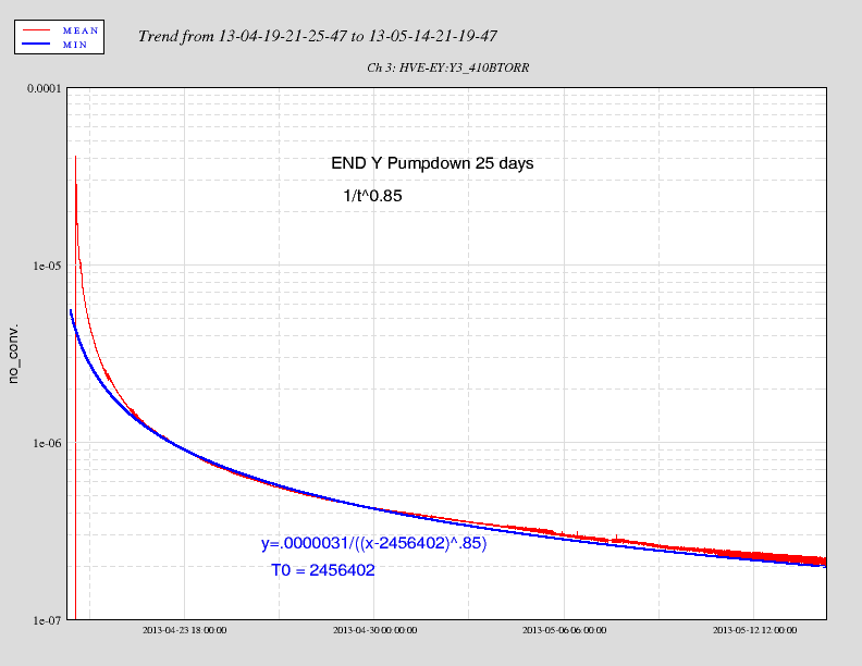
Displaying reports 82081-82100 of 86276.Go to page Start 4101 4102 4103 4104 4105 4106 4107 4108 4109 End
Reports until 19:12, Wednesday 26 September 2012
LHO General
patrick.thomas@LIGO.ORG - posted 19:12, Wednesday 26 September 2012 (4313)
plots of dust counts
Attached are plots of dust counts > .3 microns and > .5 microns in particles per cubic foot. I got errors when I tried to include plots of the dust counts at end Y, so these are not included.
Non-image files attached to this report
LHO General
patrick.thomas@LIGO.ORG - posted 19:07, Wednesday 26 September 2012 (4310)
dust monitors
I worked on the code for the dust monitors. This repeatedly interrupted the data read from the dust monitors at end Y between 9:09 AM and 6:04 PM. The code is reverted back to the code in svn. It is about complete and I hope to install it tomorrow.
X1 SUS
mark.barton@LIGO.ORG - posted 18:42, Wednesday 26 September 2012 - last comment - 14:47, Monday 07 April 2014(4312)
Taking more BSFM02 TFs
Mark B.

Resuming work on BSFM02. Will take damped and undamped TFs and damped and undamped spectra.
Comments related to this report
mark.barton@LIGO.ORG - 22:19, Wednesday 26 September 2012 (4314)
Mark B.

Done for the day. Undamped TF data is 

2012-09-26_1900_X1SUSBSFM02_M1_*_WhiteNoise.xml, 

and damped TF data is 

2012-09-26_2000_X1SUSBSFM02_M1_*_WhiteNoise.xml . 

Plots for these data set are appended. I've added the appropriate lines to plotallbsfm_tfs.m and committed it but I haven't run it - I want to check that it does the right thing with data taken on H2 but filed as X1.

Spectra time segment starts are

startTimeRef.gps = 1032753893; % GPS Start Time Damping OFF
startTimeRes.gps = 1032752625; % GPS Start Time Damping ON

I still need to generate plots for these and the ones earlier today, but as mentioned previously, first I have to modify plotbsfm_spectraBSFM02.m to accept X1 data (the script it's based on was hard-wired to L1/H1/H2).
Non-image files attached to this comment
mark.barton@LIGO.ORG - 09:47, Thursday 27 September 2012 (4319)
Mark B.

Here the comparison plot with all the BSFM02 data plus some for the real H2 FMY and X2 BSFM06. The noise in the BSFM02 data sets is rather worse than X2 BSFM06 (but comparable to H2 FMY), so it looks like we don't have the best drive parameters. However it does look like noise and there don't seem to be any significant features common to the noisy bits of 2012-09-25_1100 and 2012-09-26_0900.
Non-image files attached to this comment
mark.barton@LIGO.ORG - 16:16, Monday 08 October 2012 (4396)
Mark B.

After some discussion with Stuart, I processed the spectrum data from 7/26/12 morning and evening two ways. First I used a custom plotbsfm_spectraBSFM02.m to process it as X1/BSFM02/BUILD01 with tags of 2012-09-26_0900 (morning) and 2012-09-26_1900 (evening) with names like

^/trunk/BSFM/X1/BSFM02/BUILD01/SAGM*/Results/2012-09-26_*900_X1SUSBSFM02BUILD01H2:SUS-FMY_*.pdf

So if anyone is looking for the data by following the directory structure in the usual fashion for a Phase 1b test, appropriate plots will be there. The captions in these plots also specify X1 BSFM02 primarily and H2 FMY secondarily.

We also used the stock plotbsfm_spectra.m to process the data purely as H2:FMy with names like

^trunk/BSFM/H2/FMY/SAGM*/Results/2012-09-26_1900_H2SUSFMY_*.pdf

This is so that it can be found by the stock version of plotallbsfm_spectra.m, which Stuart felt was too much hassle to customize. We added two new lines to the measList section with comments to the effect that the suspension in each case was really BSFM02.

Attached is a set of comparison plots with the morning and afternoon's data. Unfortunately we couldn't include the 'L1','BS','2012-09-24_1200' dataset because it doesn't seem to have been committed from LLO.

Non-image files attached to this comment
mark.barton@LIGO.ORG - 14:47, Monday 07 April 2014 (11126)

In preparation for the Acceptance review, I redid the TF plots with up-to-date comparisons.

Red: 3IFO Phase 1b undamped (2012-09-26_1900)

Pink: 3IFO Phase 1b damped (2012-09-26_2000)

Black: H1 BS Phase 3b undamped (2013-07-30_1059269030)

Orange: L1 BS Phase 3b undamped (2013-08-29_0900)

Because the data was taken on a mechanical test stand in the LVEA with other work going on around, it is somewhat noisy (especially up to about 0.6 Hz in most DOFs and throughout in P) and the damping is a bit strong, but the peaks in the undamped TFs are very clean and in exactly the right positions.

I also redid the spectra with comparisons.

Green: 3IFO BS 2012-09-26_0900

Red: 3IFO BS 2012-09-26_1900 (later the same day)

Cyan: H1 BS 2013-02-25_1000 (on BSTST test stand)

Purple: H1 BS 2013-07-24_1400

Blue: L1 BS 2013-11-27_0930

Non-image files attached to this comment
LHO General
patrick.thomas@LIGO.ORG - posted 18:14, Wednesday 26 September 2012 (4311)
Ops Summary
Dave restarted all models on h1sush34.
Filiberto to mid Y to pick up electronics.
Apollo to remove dome and door from BSC 8, place clean room on e-module and install lift jacks on the clean room for cartridge removal.
I worked on dust monitor code which interrupted data read from dust monitors at end Y.
LHO VE
kyle.ryan@LIGO.ORG - posted 17:44, Wednesday 26 September 2012 (4309)
Torqued (1)12"x(3)4.5" elec. feedthrough on NW end of HAM3
Contacted cross beam -> have one more to do (tomorrow?) on SW end of HAM3
H1 ISC
keita.kawabe@LIGO.ORG - posted 14:35, Wednesday 26 September 2012 - last comment - 23:44, Wednesday 26 September 2012(4306)
Done with HAM3 IO and ISC installation for now (Cheryl, Daniel, Keita)

Everything we planned to install at this stage was installed.

Picomotors are connected to the in-vac cable (we copied LLO cabling layout), which was connected to the connector bracket 3 upper floor in chamber, which is connected to the feed through. We connected the picomotor driver and the test interface to the feed through from outside, and all picomotor worked:

Pico 1 = ISC steering mirror just upstream of QPD sled.

Pico 2 = ISC steering mirror further upstream of QPD sled.

Pico 3 = IO steering mirror for IO QPD.

Pico 4 = ISC steering mirror that directs POP to HAM1.


We used a laser pointer and a hand held LCD QPD readout box to check the QPDs. Though it cannot test the output of individual quadrants, and though the laser pointer beam was too big (or, rather, QPDs were too small) to put the entire beam on one quadrant, both IO QPD and ISC QPDs seem to respond to the light reasonably.


Some IO components (e.g. IO black glasses and beam dumps and such) will be installed later.

Comments related to this report
cheryl.vorvick@LIGO.ORG - 23:24, Wednesday 26 September 2012 (4315)
HAM3 ISC SLED pictures:
Images attached to this comment
cheryl.vorvick@LIGO.ORG - 23:44, Wednesday 26 September 2012 (4318)
HAM3 current state:  IO and ISC optics

Still to do/install:
- install IO beam dumps on MC Trans
- install Scraper Baffles
- remove FC from 2 IO optics
- install black glass
- align
Images attached to this comment
cheryl.vorvick@LIGO.ORG - 23:32, Wednesday 26 September 2012 (4317)
IO mirrors - before cabling Picos.
Images attached to this comment
H1 INS
jodi.fauver@LIGO.ORG - posted 14:16, Wednesday 26 September 2012 - last comment - 15:18, Thursday 27 September 2012(4305)
BSC8 De-Install/BSC1 Install Prep
The Apollo crew worked on the following: craned one aLIGO garbing/staging cleanroom from the beer garden to the south side of BSC8; craned an iLIGO cleanroom from by HAM6 to the E-module; removed BSC8 south door; retrieved walking plates and three-point spreader from Y-end; and located bang boards for cleanroom use. Karen and Cris cleaned both garbing/staging cleanrooms. I staged a few things (garbing rack, staging table, foil, etc.) in the lower level cleanroom.
Comments related to this report
jodi.fauver@LIGO.ORG - 15:18, Thursday 27 September 2012 (4323)
Walking plates and three-point spreader did not make it to the corner after all. >-(
H2 SEI
vincent.lhuillier@LIGO.ORG - posted 11:42, Wednesday 26 September 2012 (4303)
Using the optical levers at low frequency (not so useful to evaluate the amplification of the length of the cavity created by HEPIs and ISIs)

Once all isolation filters are engaged on HEPIs and ISIs, the absolute motions of the optical tables are amplified by less than 10 times in the Y direction while the length of the cavity is amplified by 100 below 100mHz.

Coupling from HEPI-ISI to Test masses (figure 1)
ASDs of the pitch and the yaw of the test masses are presented in three different configurations:
- HEPI ON – ISC Y feedback (UGF: 1mHz) - ISI Damped
- HEPI ON – ISC Y feedback (UGF: 1mHz) - Sensor correction -  ISI Damped
- HEPI ON – ISC Y feedback (UGF: 1mHz) - Sensor correction - ISI Damped & Controlled (100mHz blend with T240s)

This figure 1 shows that:
- When HEPIs at BSC-6 and BSC-8 are ON, ETM & ITM are tilting in pitch and yaw by the same amounts at all frequencies. Blend filters of the IPS on HEPIs have a 800mHz corner frequency (below 100mHz, the blend filters transfer functions are close to 1). Consequently, no amplifications of the pitch and the yaw of the test masses are expected below 100mHz.
- When the STS-2 are introduced in the HEPI super sensor blend (sensor correction), the aggressive high pass filters with a 100mHz corner frequency increase the absolute motion in the X, Y and Z directions. An amplification of the pitch and the yaw of the test masse can be expected due to eventual cross couplings from longitudinal, transverse and vertical displacement of the HEPI-ISI to the test masses. But strangely, only the rotations of the ETM are increased at low frequency. ITM rotations are unchanged or reduced. In this case, the “apparent tilt" seen by the optical levers is probably due to the longitudinal displacement of the test mass in the Y direction (cf Sensitivity of the optical levers to longitudinal displacement)
- Once the ISI is controlled (with blend at 100mHz => maximum amplification at 60mHz), pitch and yaw of the ETM are increased while pitch and yaw of the ITM is moderately increased. When HEPIs (sensor correction) and ISIs are controlled, apparent pitch and yaw of the ETM are amplified by 50 while pitch and yaw of the ITM are not amplified. Remember that the length of the cavity is increased by 100 in this configuration.

Sensitivity of the optical levers to longitudinal displacement
Pitch and yaw seen by the optical levers can be due either the tilt of the mirror or the longitudinal displacement of the test mass as shown in figure 2. In the case of a pure translation of the test mass, the “apparent tilt” seen by the optical levers can express as a function of the longitudinal displacement of the test mass where:
Tilt~d1*dl/(d2^2)
ETM optical levers are about 70 times more sensitive to the longitudinal displacement than the ITM optical levers.

Transfer functions from the “apparent pitch and yaw” (translation in the case of ETM?) of the test masses to the length of the cavity (figure 3).
Transfer functions from pitch and yaw of the test masses to the length of the cavity are presented below in three configurations:
- HEPI ON – ISC Y feedback (UGF: 1mHz) - ISI Damped
- HEPI ON – ISC Y feedback (UGF: 1mHz) - Sensor correction -  ISI Damped
- HEPI ON – ISC Y feedback (UGF: 1mHz) - Sensor correction - ISI Damped & Controlled (100mHz blend with T240s)

When there is no sensor correction, coherences between the apparent tilt (signal probably dominated by actual tilt) of the test masses and the length of the arm are close to 0. But when the controllers are engaged, the contribution of the displacement of the test mass in the tilt signals is probably not negligible especially at ETM. When the sensor correction is engaged, coherences in pitch and yaw are pretty high (0.8) on the ETM around 60mHz and stay at 0 on the ITM.
It seems that the oplev are seeing the translation of the test mass at EY. Consequently, the measured transfer functions are from “translation of the test mass” to length of the cavity. Having a good coherence close to 1 on ETM and 0 on ITM is not abnormal.

Transfer functions ISI to OPLEV (figures 4, 5, 6)
T
ransfer functions from the ISI to the optical levers show a good coherence from the ISI drives (especially in the Y direction) to the optical levers (pitch and yaw) of ETM. The coherence is null on ETM. Oplev are not sensitive to vertical displacement of the testmass, coherences in the case of a Z-drive are low or null.

Non-image files attached to this report
H1 CDS
david.barker@LIGO.ORG - posted 09:47, Wednesday 26 September 2012 (4301)
HAM SEI and SUS front end restarts

We trouble shot a problem with ISI for HAM2. It required a hard power cycle of h1seih23-IOChassis. During the trouble shooting h1sush34 was Dolphin glitched and the MC2, PR2 models froze. I have just restarted all the models on h1sush34.

X1 SUS
mark.barton@LIGO.ORG - posted 09:11, Wednesday 26 September 2012 - last comment - 16:44, Wednesday 26 September 2012(4300)
Taking damped TFs for BSFM02
Mark B.

Need to get a set of TFs for BSFM02 with damping on. Starting now.
Comments related to this report
mark.barton@LIGO.ORG - 16:44, Wednesday 26 September 2012 (4308)
Mark B.

Done for now. Successfully took a set of damped TFs with time label "0900". I noticed at the end of the first attempt that the M1 and User DACKILL WDs had tripped. Looking at trends put the event at 10:18 local, which was just after the third drive file had been saved, so I redid T, V and Y, overwriting the original files. See attached for plots.

I also identified 20 minute data stretches for damped and undamped spectra:

startTimeRef.gps = 1032727669; % GPS Start Time Damping OFF
startTimeRes.gps = 1032726356; % GPS Start Time Damping ON

Again, because BSFM02 is being tested on H2 not X1, I had to create a custom plotting script, plotbsfm_spectraBSFM02.m. It currently has one bug/misfeature to do with saving the plots (it only saves plots for L1, H1 and H2), but I've committed it for now anyway and will work on it more later.

I plan to return this evening to repeat all measurements in quiet time.
Non-image files attached to this comment
H1 SUS
betsy.weaver@LIGO.ORG - posted 19:22, Tuesday 25 September 2012 - last comment - 16:10, Wednesday 26 September 2012(4299)
H1 MC3 Phase 2a TFs

There seems to be some pretty good Vertical to Pitch coupling we need to hunt down tomorrow on this sus.  TFs look OK in some DOFs, but not this one.

Comments related to this report
betsy.weaver@LIGO.ORG - 16:10, Wednesday 26 September 2012 (4307)

We've corrected for some observed pitch error in the tablecloth which mounts the top BOSEMs.  This has seemingly corrected the P-V coupling so I'll rerun the TFs tonight-ish.

H1 SUS
betsy.weaver@LIGO.ORG - posted 19:22, Tuesday 25 September 2012 (4298)
H1 MC3 Phase 2a TFs

There seems to be some pretty good Vertical to Pitch coupling we need to hunt down tomorrow on this sus.  TFs look OK in some DOFs, but not this one.

LHO General
patrick.thomas@LIGO.ORG - posted 18:55, Tuesday 25 September 2012 (4297)
dust monitors
Last Friday I spent most of the morning compiling, testing and modifying the code to read and control the dust monitors. This interrupted the data read from end X. I ended up reverting back to the old code sometime before 12:30 PM.

Today I spent most of the morning doing the same, except it interrupted the data read from end Y. I ended up reverting back to the old code around noon.

This afternoon Michael R. swapped the dust monitor in the H1 PSL Anteroom (LVEA location 16), to investigate if the high counts for particles > .3 microns read last night might be due to an error in the instrument. I ended up restarting the code for all the dust monitors in the LVEA after this was completed.

I received an error trying to plot the particle counts, so I do not have plots to attach yet.
Displaying reports 82081-82100 of 86276.Go to page Start 4101 4102 4103 4104 4105 4106 4107 4108 4109 End