arnaud.pele@LIGO.ORG - posted 17:46, Thursday 24 January 2013 (5252)
ITMy TFs
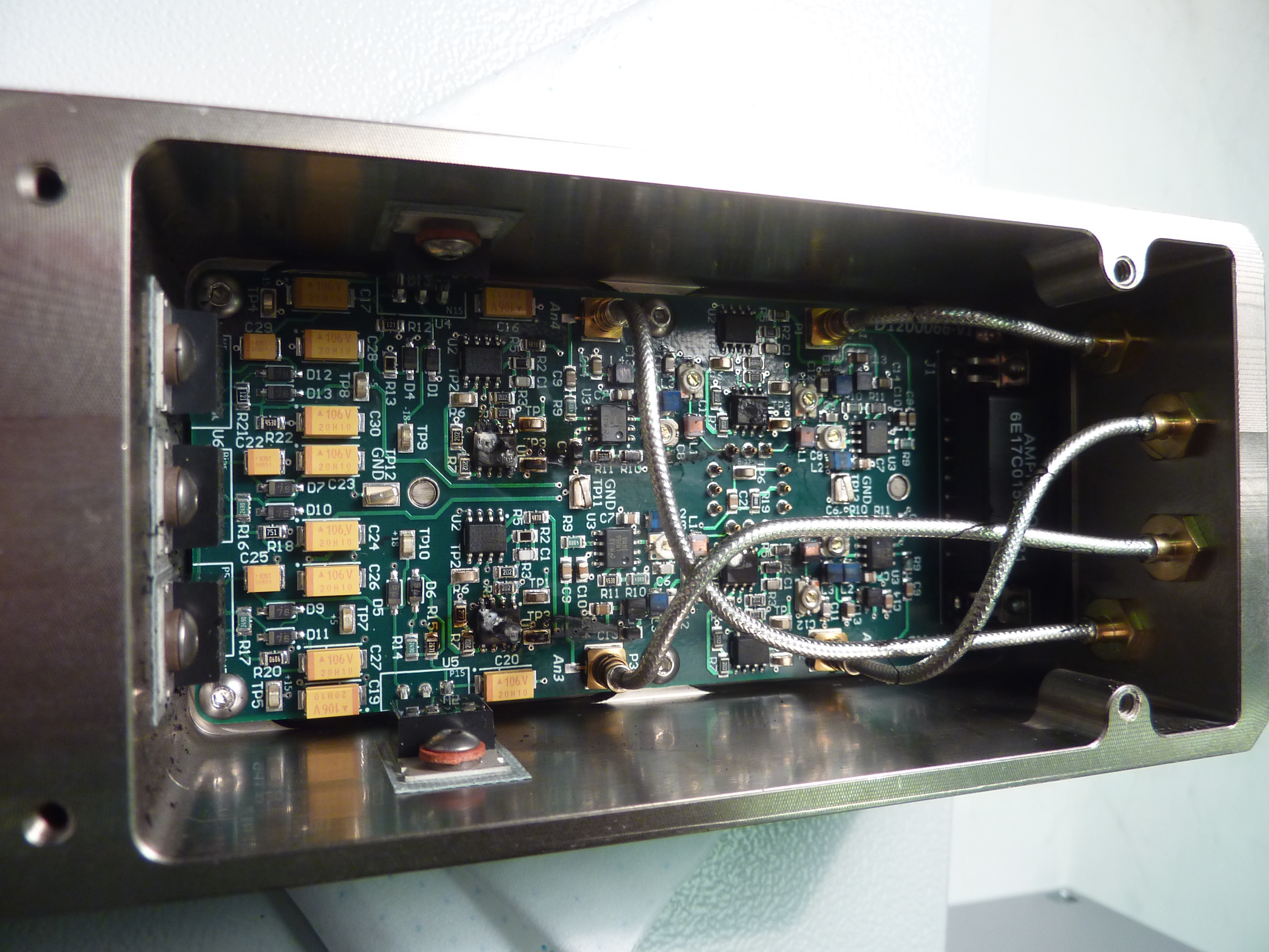
Mark B and Arnaud P.

We took DTT transfer functions on M0 and R0 of ITMy:

^/trunk/QUAD/ITMY/SAGR0/Data/2013-01-24_1300_H1SUSITMY_M0_*_WhiteNoise.xml
^/trunk/QUAD/ITMY/SAGR0/Data/2013-01-24_1300_H1SUSITMY_R0_*_WhiteNoise.xml

Main chain looks very good. Reaction chain is a bit messy but very similar to previous measurements from when it was H2 ITMy.

Next step is to work with IAS to set the pitch of the main chain.
Non-image files attached to this report