Mostly for myself (and to keep track in the event some push out to a subsequent vent), the following are items SUS still needs to do in HAM2/3 before the chamber is officially checked off the install list.
To be done in the next day:
Tweek lower stage AOSEMs to 50% OLV
Swap PFA EQ stop tips with fluorel/glass tips
Install Vibration Absorbers
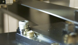
Lock all EQ nuts
Things we're pushing toafter the next vent in the new year:
Re-check heights of prisms to table surface
Perform B&K Hammer testing
Round of FC cleaning since duration of chamber-work exposure to MC1 and MC3 optical faces was many weeks (duplicating the LLO schedule)
Install PR3, PRM, and all associated install and testing steps, etc. Balance of install/alignment procedure...