corey.gray@LIGO.ORG - posted 21:40, Tuesday 17 September 2024 (80159)
H1 Calibration Measurement Post-Maintenance DAC Changes Today (broadband headless + simulines)
Since H1 was thermalized after this lock which was after a long/busy Maintenance Day, was asked to run another calibration. Notified LLO & Virgo via chat & TeamSpeak to give them a heads up about H1 dropping out of Triple Coincidence for 30min for calibration work.
Measurement NOTES:
- Following instructions (link)
- H1 at NLN for for over ~6hrs
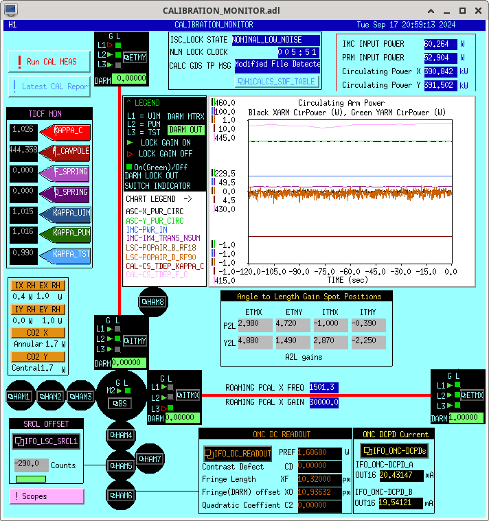
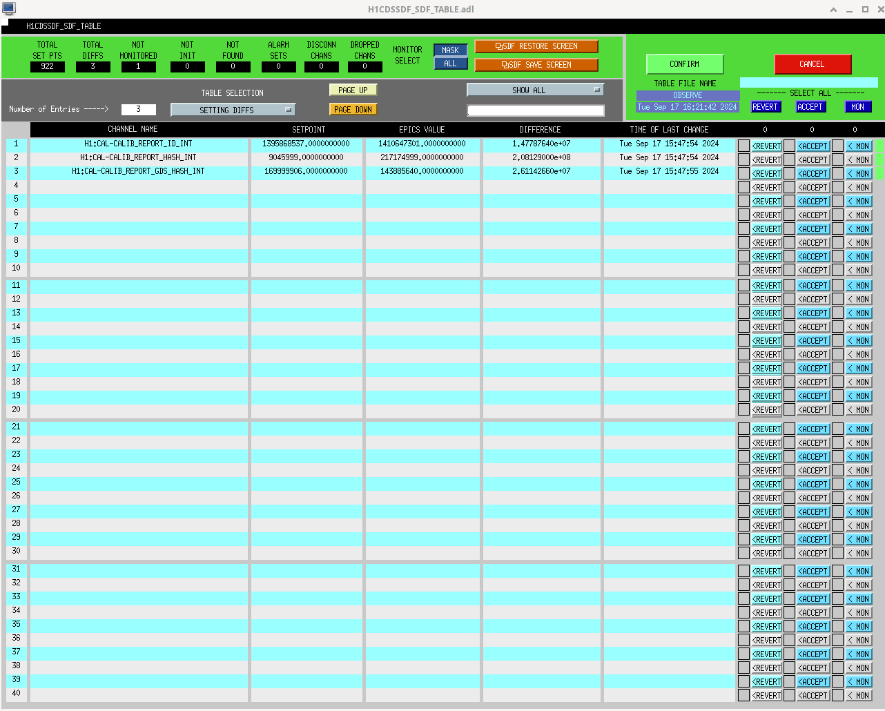
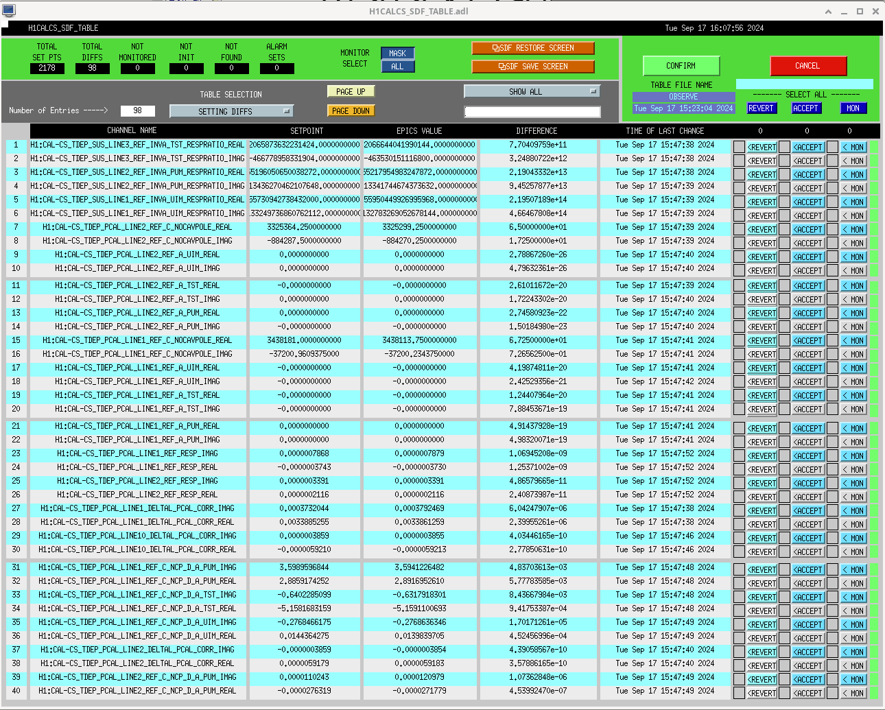
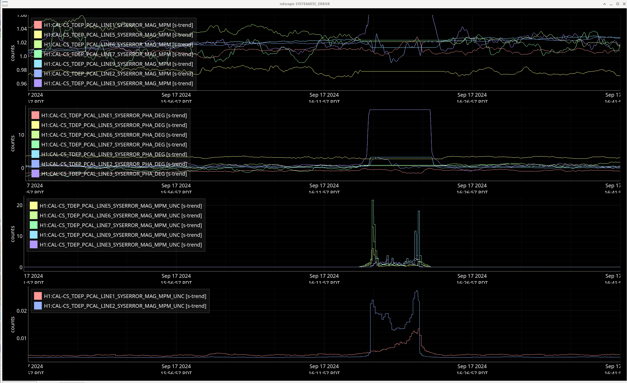
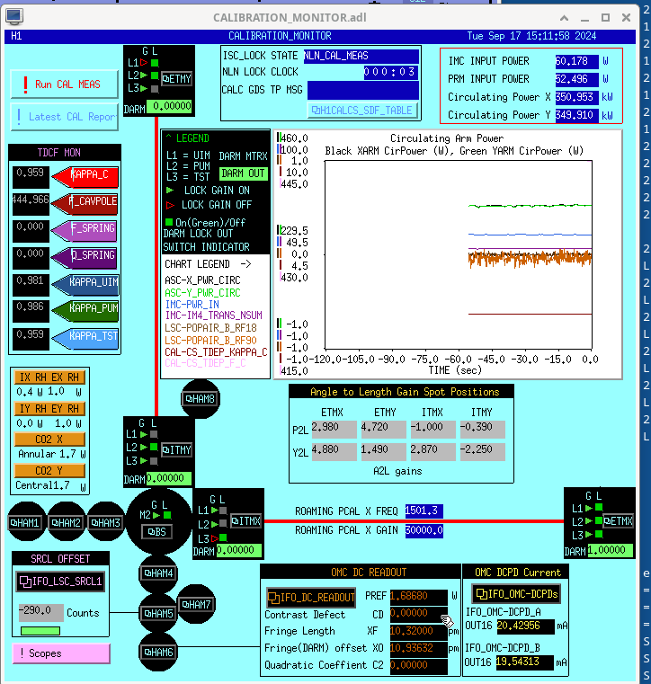
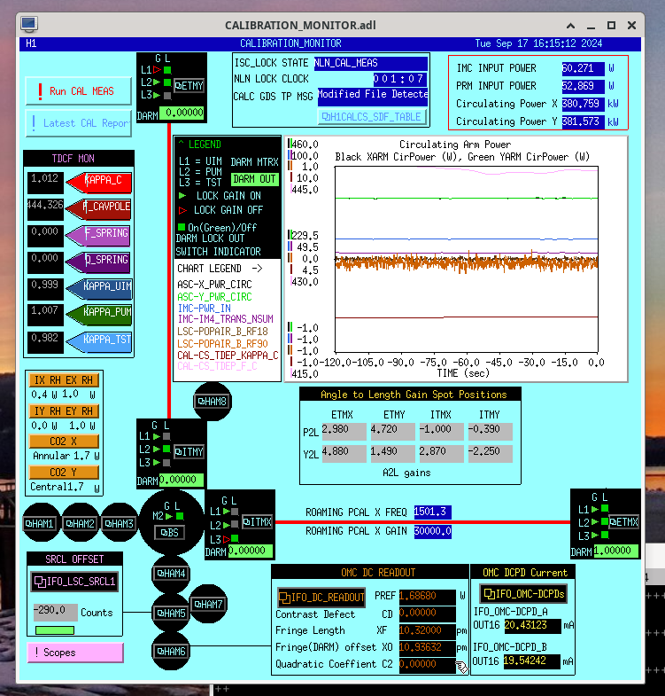
- Calibration_Monitor medm screenshot is attached
- 0402-0436 Out of Observing, ISC LOCK to NLN_CAL_MEAS & Observatory Mode to CALIBRATION
- 0402-0408 Broadband measurement run
- Measurement at: /ligo/groups/cal/H1/measurements/PCALY2DARM_BB/
- 0408-0436 Simullines measurement
- gps START time: 1410667735.498060
- gps STOP time: 1410669674.947983 (or 0440utc including post processing)
- Files writtten to subfolders here: /ligo/groups/cal/H1/measurements
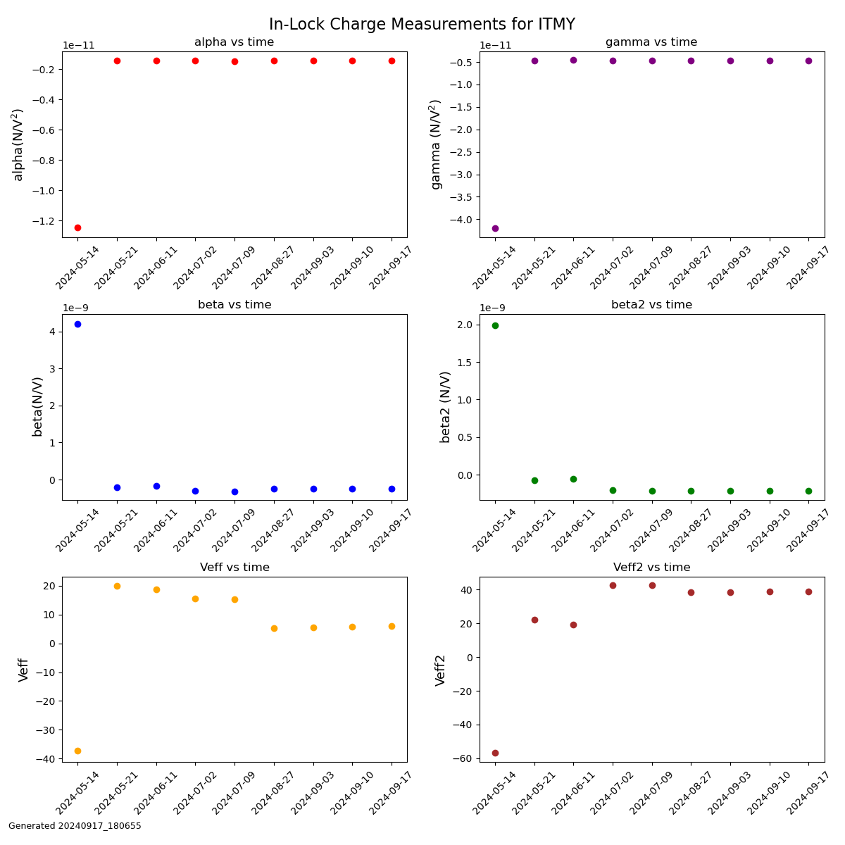
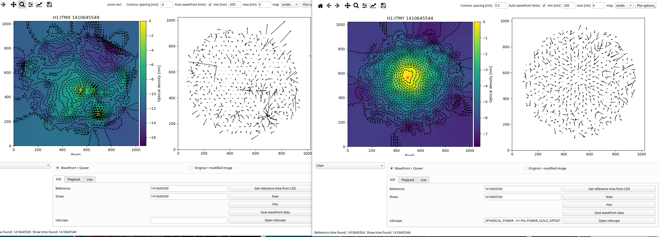
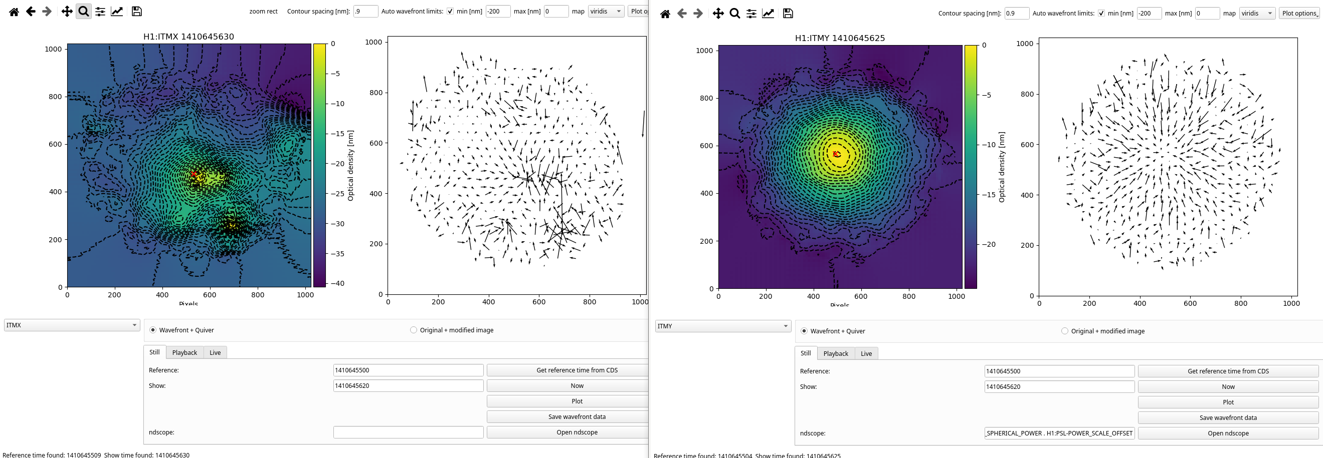
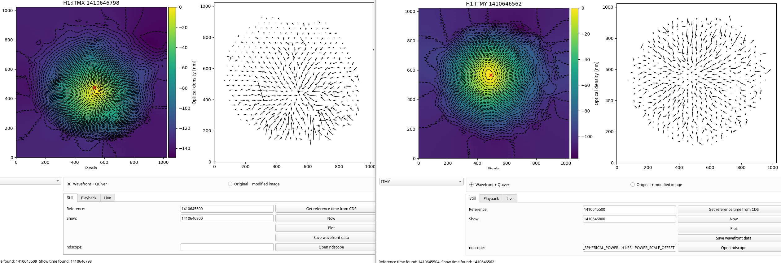
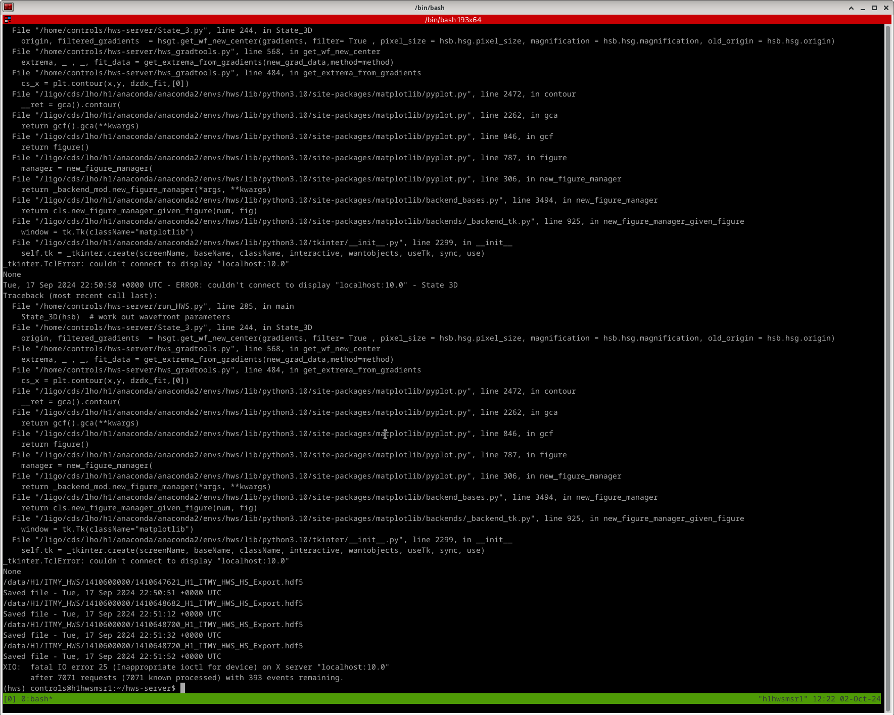
Images attached to this report