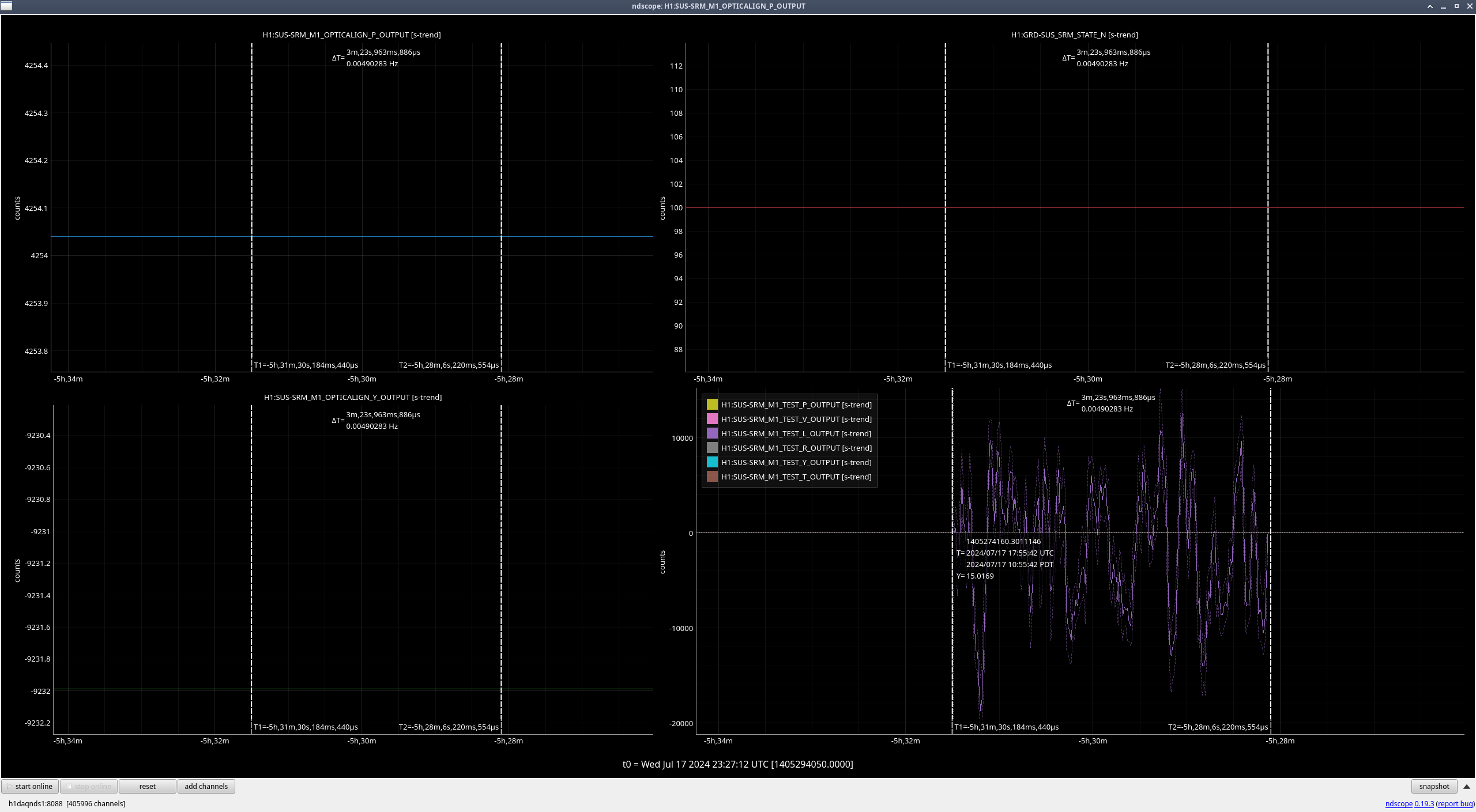
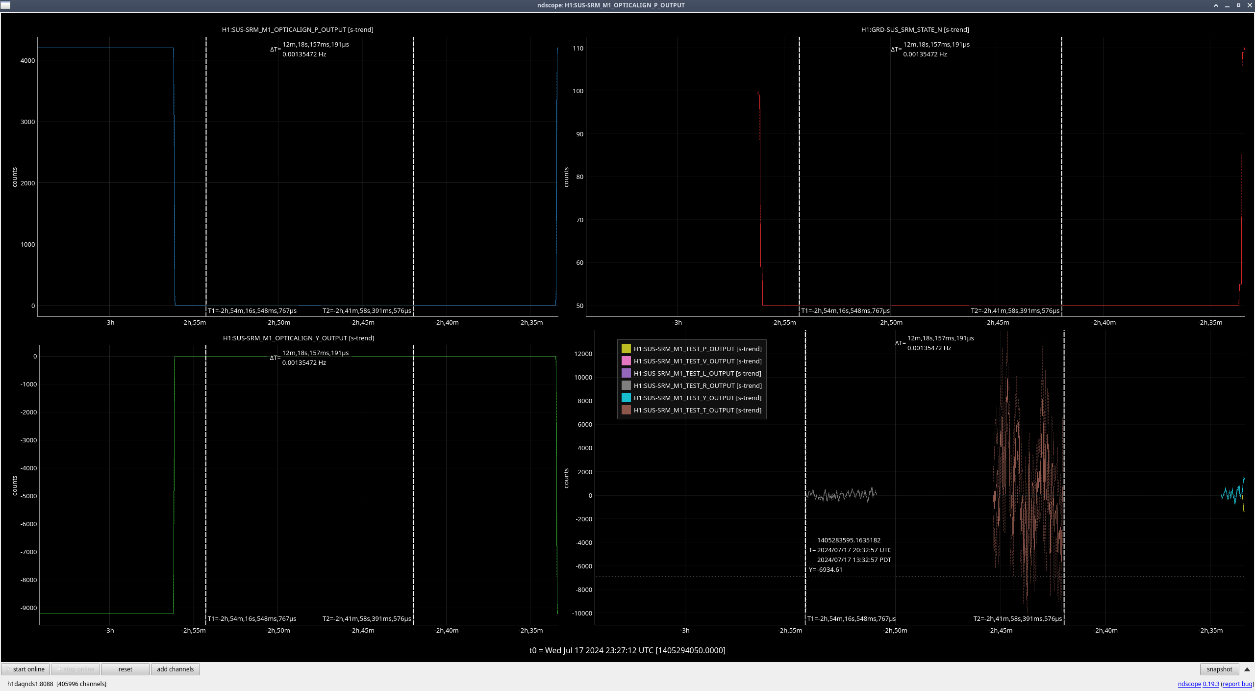
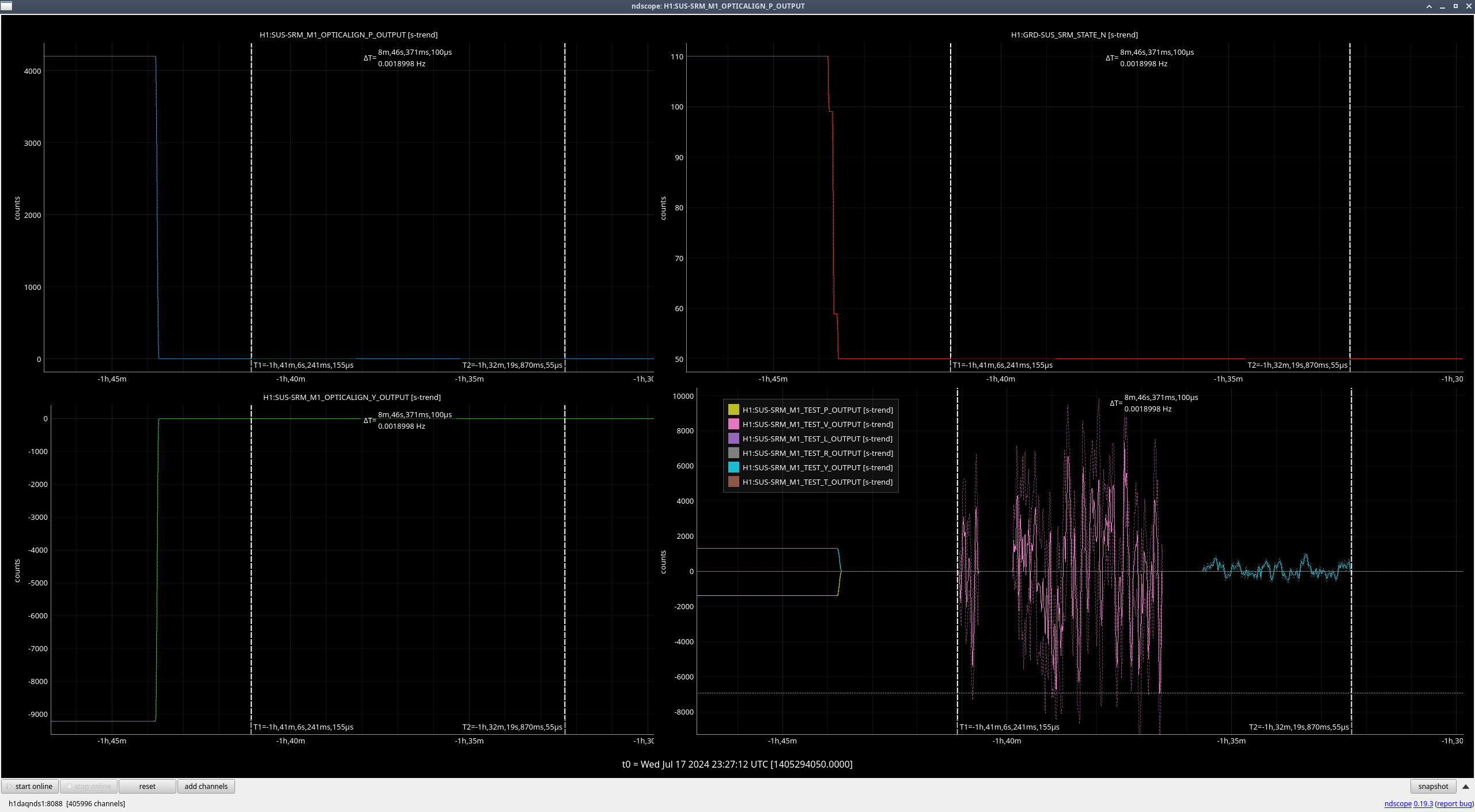
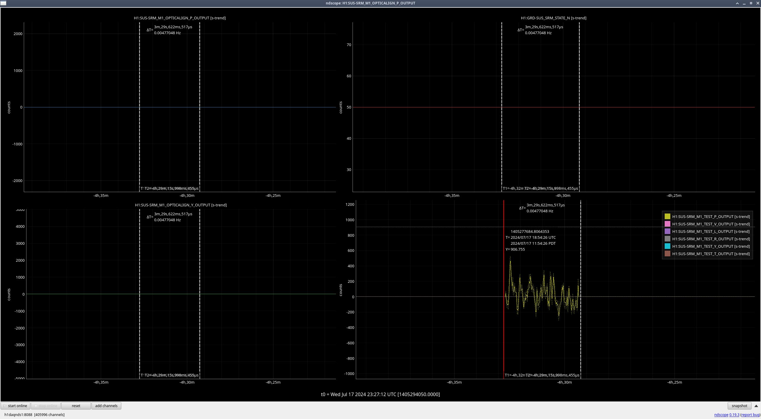
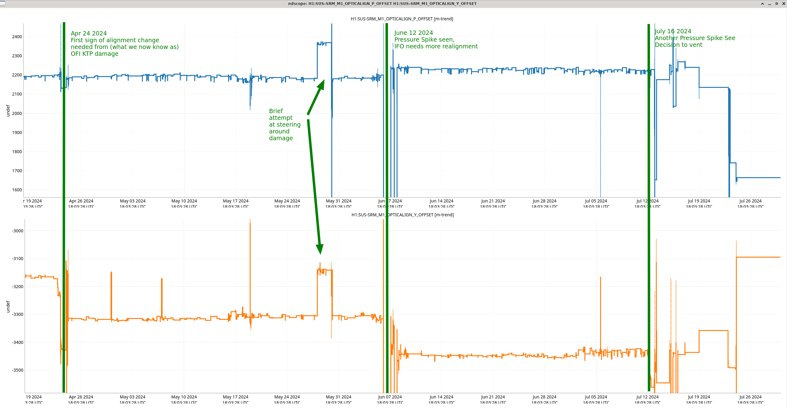
I was running the TFs for SRM to confirm that the suspension is good before we close HAM5, but the transfer function for L was a noticable amount lower in magnitude as compared to the measurements taken on July 17th right before we vented HAM5(pdf). We reran L but this time with the OPTICALIGN offsets turned ON, and the results matched our pre-vent measurements, which seemed strange and prompted looking into whether the RT OSEM has a problem. I've looked back at the state of SRM when the July 17th transfer functions were run, and T, V, R, P, and Y were run in DAMPED and OPTICALIGN offsets were OFF(T&R, V&Y, P). HOWEVER, when the L transfer function was run, SRM was ALIGNED and OPTICALIGN offsets were ON (P: 4254, Y: -9231)(L pre-vent). So that's why today's regular (offset OFF) L didn't match the pre-vent L, and why my second measurement of L with the offset on did match.
Yaw is the only other dof that was affected by the offsets being ON vs OFF, but the pre-vent Y measurements were taken with the offsets OFF, and these match with today's offset OFF measurements so we're all good there.
I'm not sure if there are still concerns about the RT OSEM on SRM M1, now that we know why L matches the pre-vent L, so I'm not sure if these results clear us for closing HAM5 or not.
Main set of measurement results (2024-08-01_2000) - SRM DAMPED, OPTICALIGN offset OFF:
$(sussvn)/HSTS/H1/SRM/SAGM1/Results/2024-08-01_2000_H1SUSSRM_M1_ALL_TFs.pdf
Second set of measurement results (2024-08-01_2200) - SRM DAMPED, OPTICALIGN offset ON:
$(sussvn)/HSTS/H1/SRM/SAGM1/Results/2024-08-01_2200_H1SUSSRM_M1_ALL_TFs.pdf
Full comparison of Pre-Vent, Post-Vent offset OFF (main) set, and Post-Vent offset ON set
$(sussvn)/HSTS/Common/Data/allhstss_2024_July17vAug01_H1SUSSRM_M1_PreVsPostOFIVent_ALL_TFs.pdf
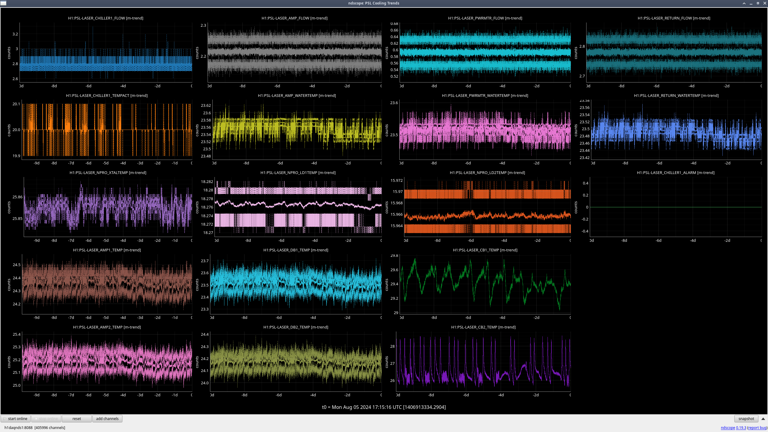
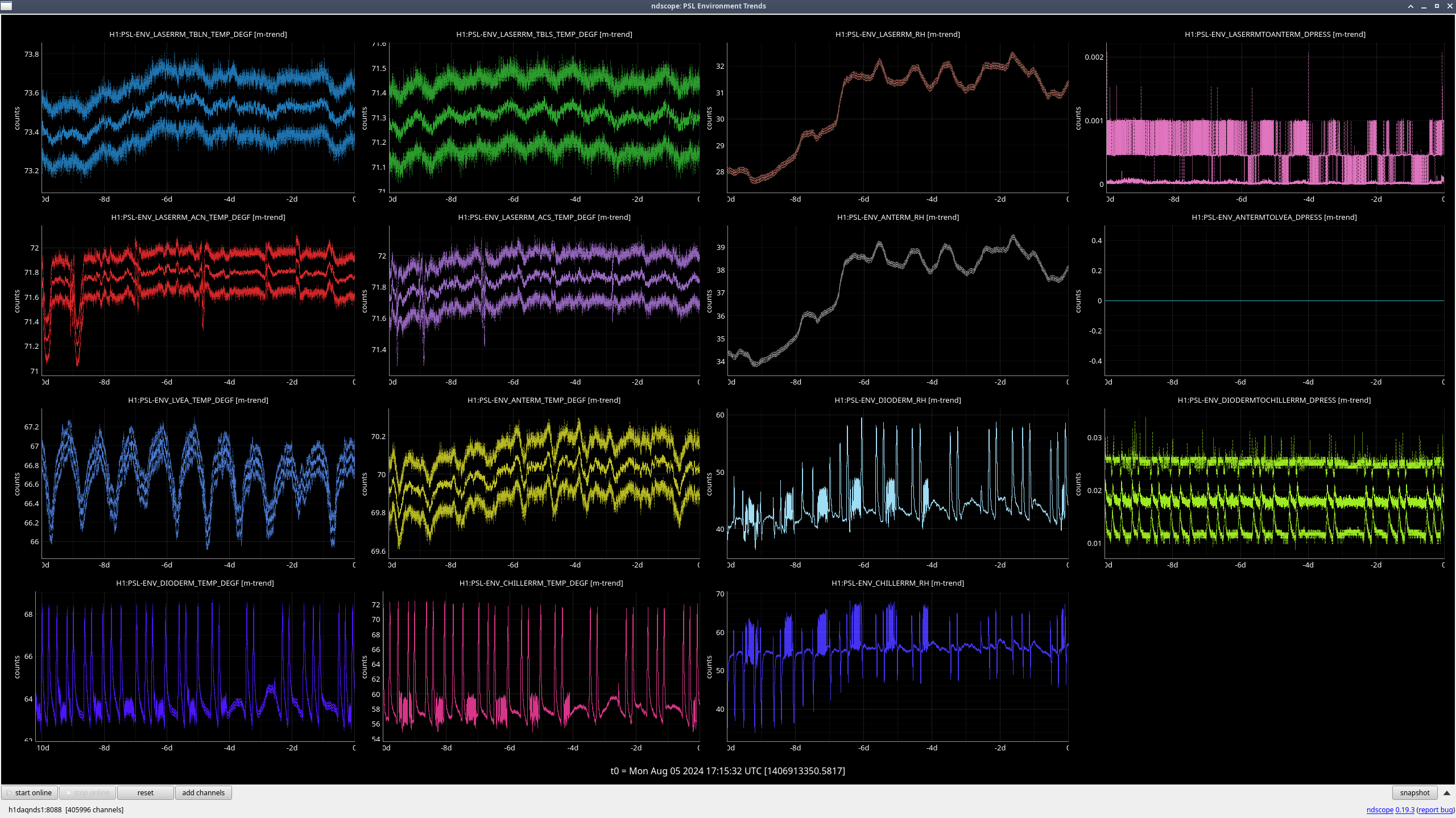
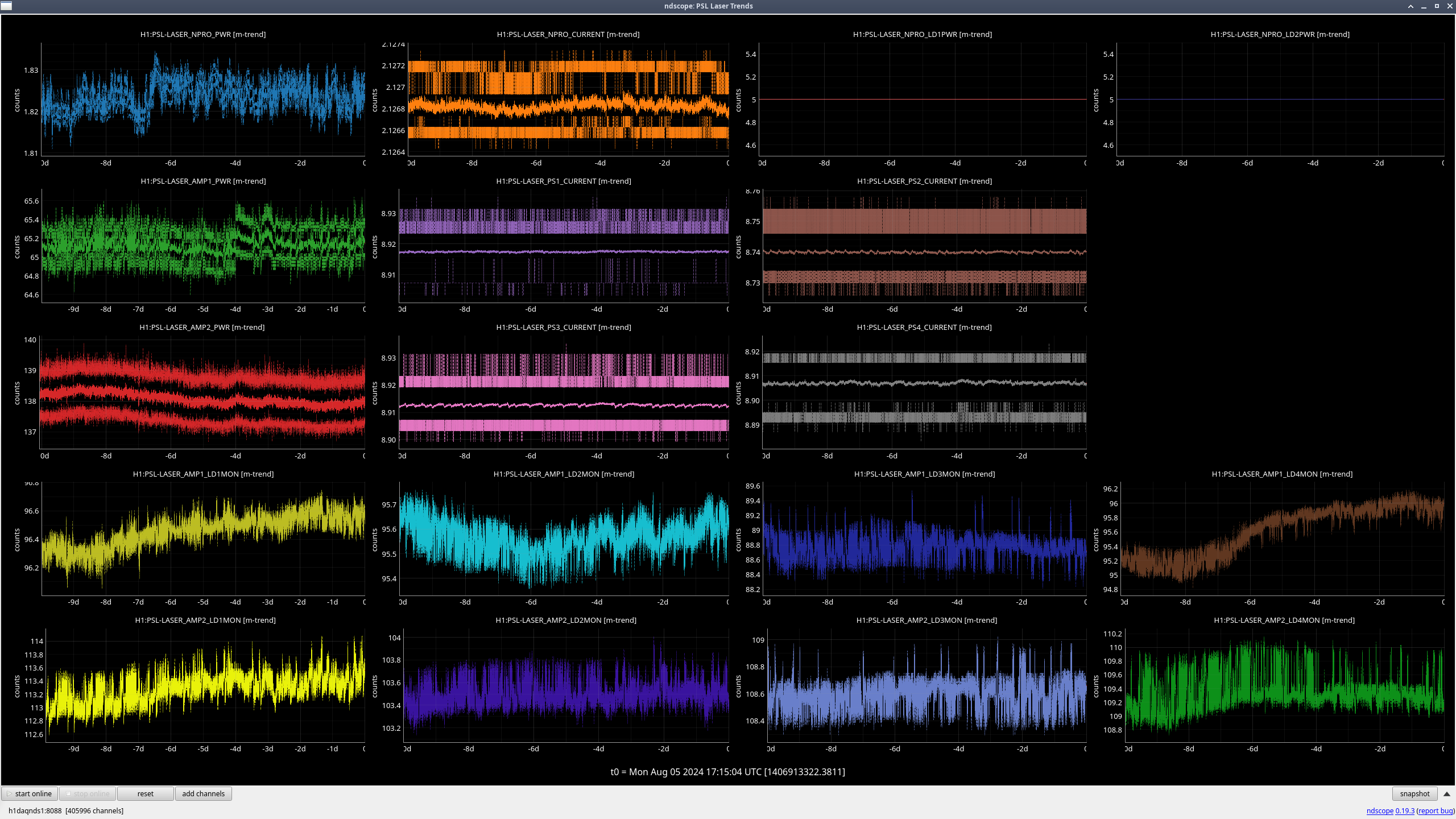
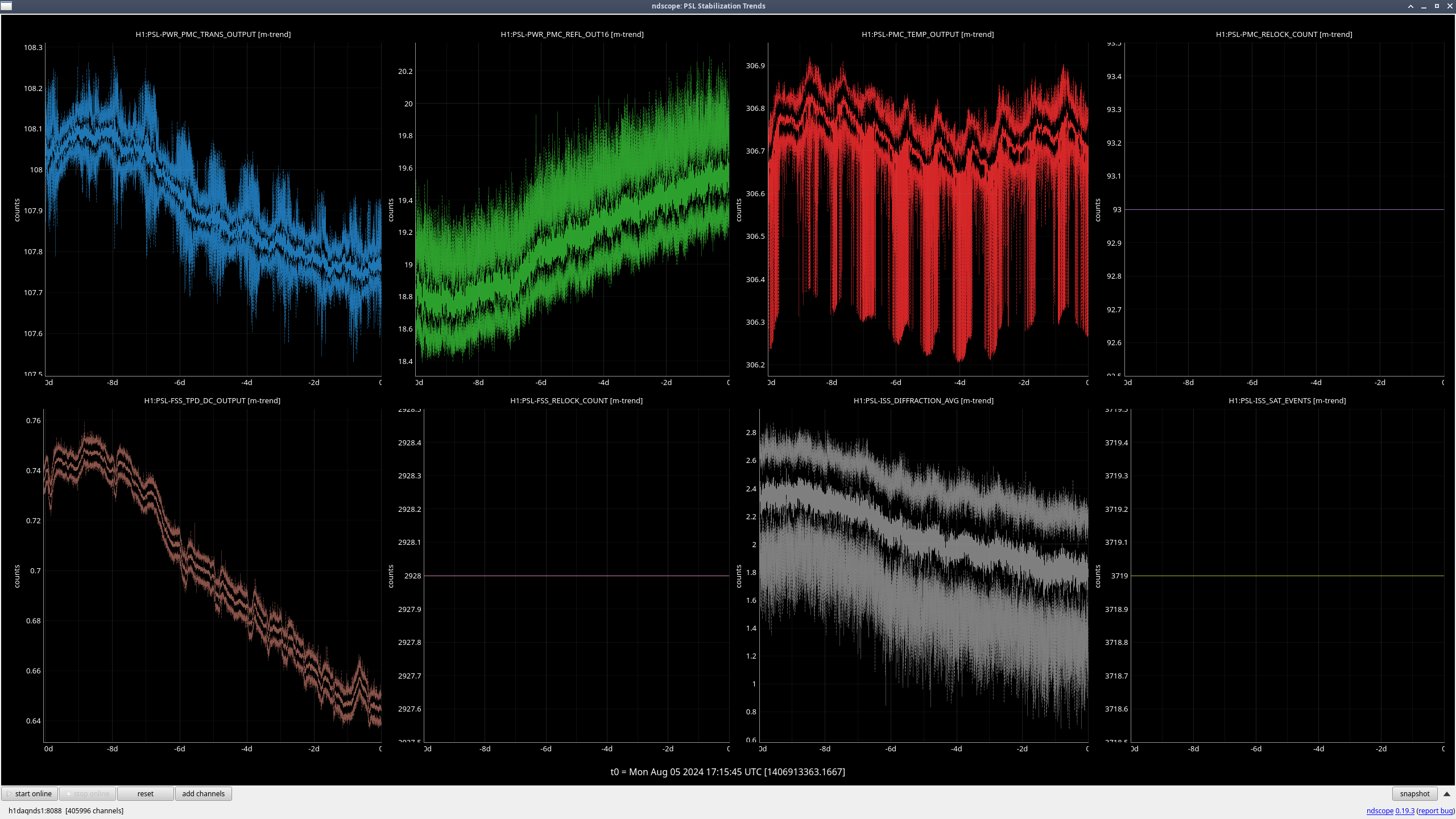


I changed the make-up air speed back to its nominal setting of 20% at ~19:15 UTC (12:15 PDT) on 8/7/2024. The make-up air being on did cause the Laser Room temperature to drop by a couple degF, which in turn caused the output power of both Amp1 and Amp2 to drop by ~2W each; will monitor over the next several hours to ensure things return to normal as the enclosure returns to its normal thermal equilibrium.