Nothing wrong with our previous reflection dip measurements with alumina.
We (MichaelL, StephenA, MattH, Gabriele, Elenna and myself) had a meeting in the morning.
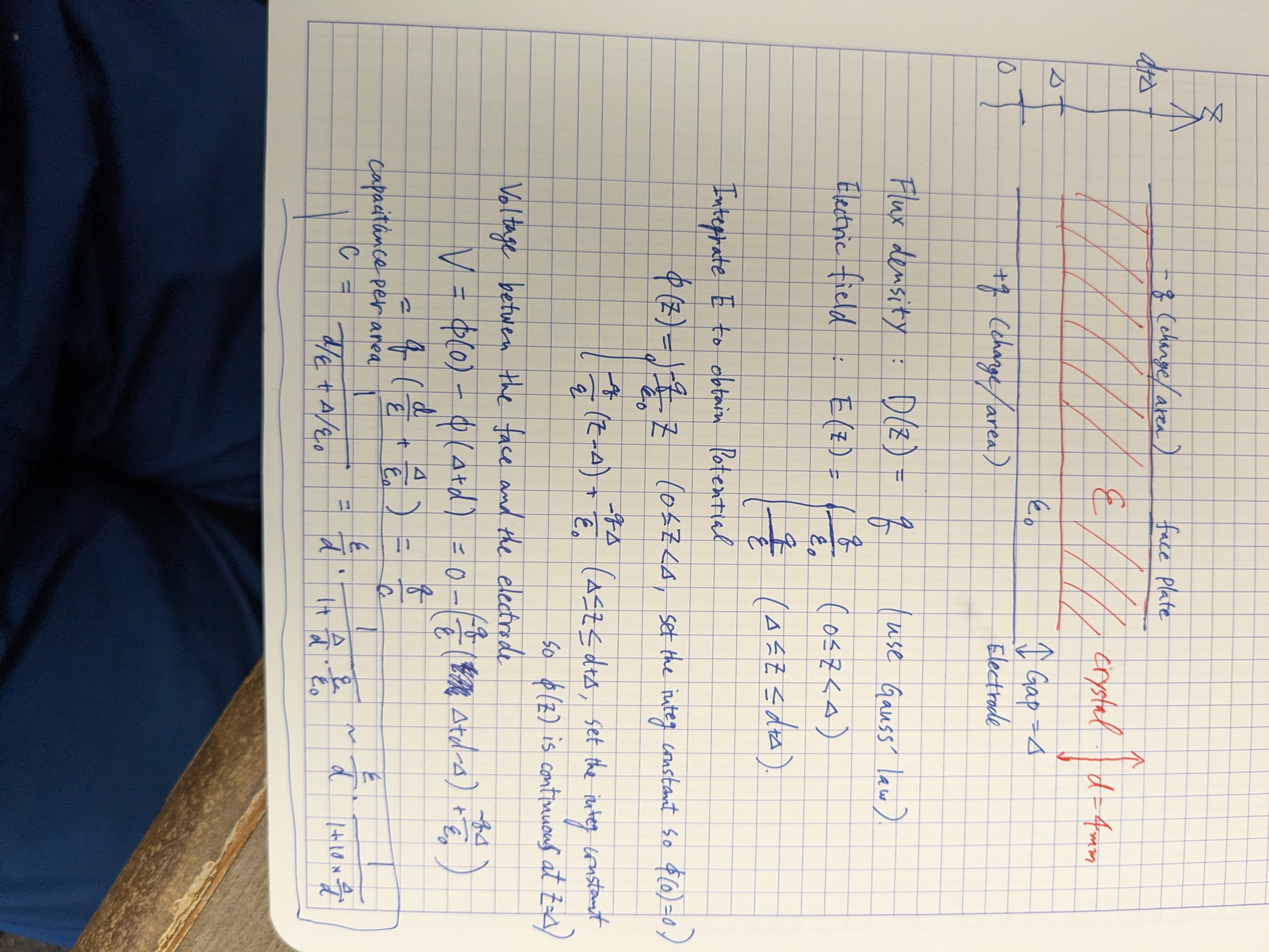
Looking at the "with the alumina" reflection screen shots, Michael didn't see any serious problem so we decided that the electrode-crystal-face plate capacitance is OK. We won't worry about that, we'll just make sure that there's no visible gap.
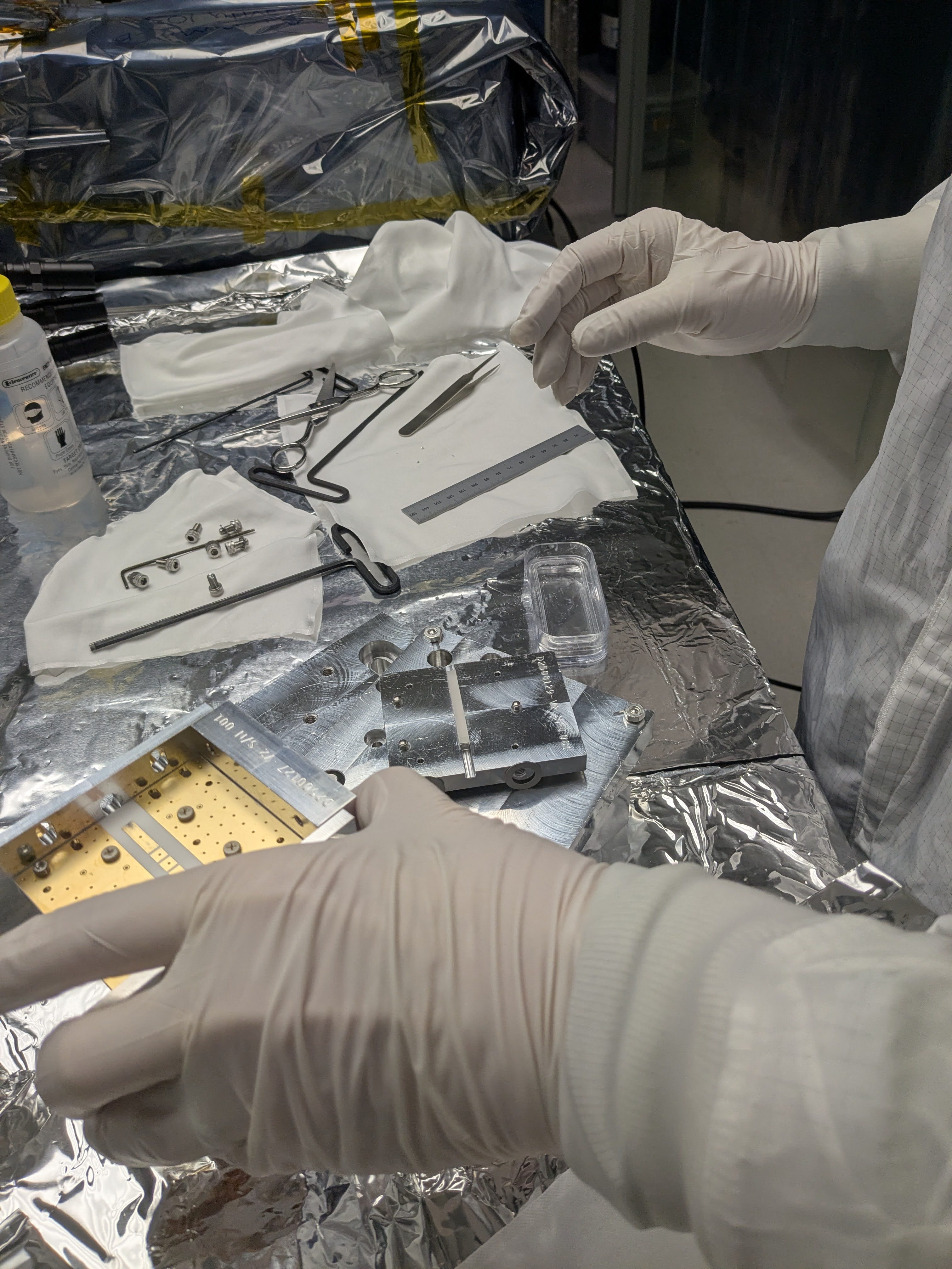
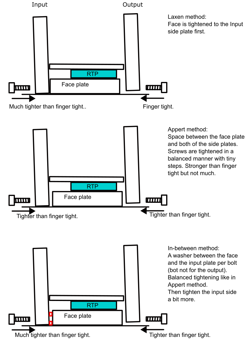
Third mounting method ("in-between") was proposed and tested.
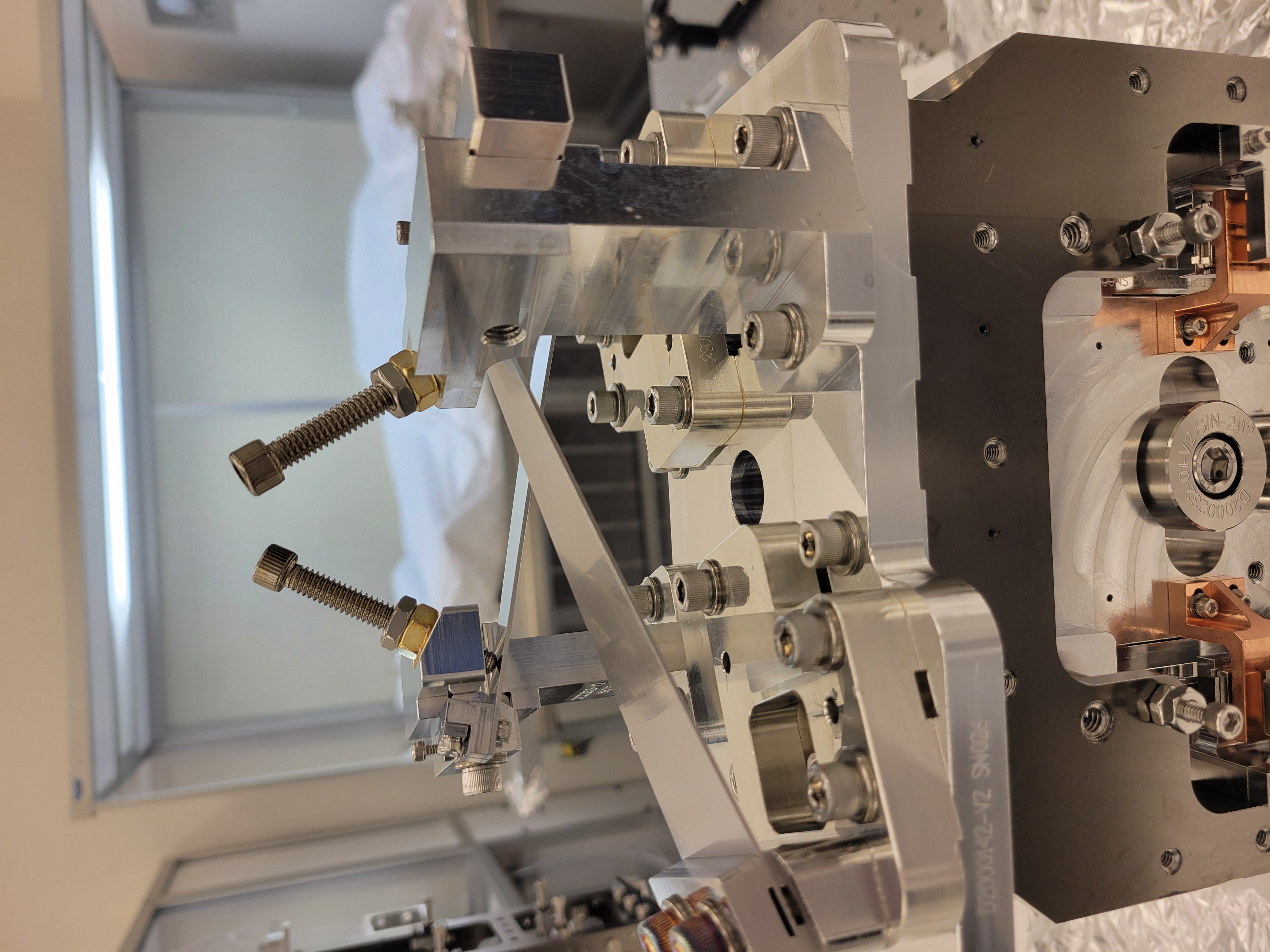
Stephen proposed an in-between method where we use washers between the input side plate and the front plate (bottom of three_methods.png cartoon). After the washer contacts the face plate AND the input side plate, screws are gently tightened in a balanced manner like in Appert method. (In a retrospect this is not that different from Laxen method except the way screws are tightened and that the input side plate contacts with the face plate at two points.)
We first tried to use a presicion thickness shim washer for 1/4-20 screws but I didn't like that they're too big. We ended up using smaller stamped washers that is 0.039" or 0.99mm thick (according to the caliper). That's not flat but seems OK to me.
This in-between method worked in that it was doable and gave us a reasonable reflection dips.
Mechanical stability test of Appert method and in-between method. The latter is better, we'll use that for the real RTP.
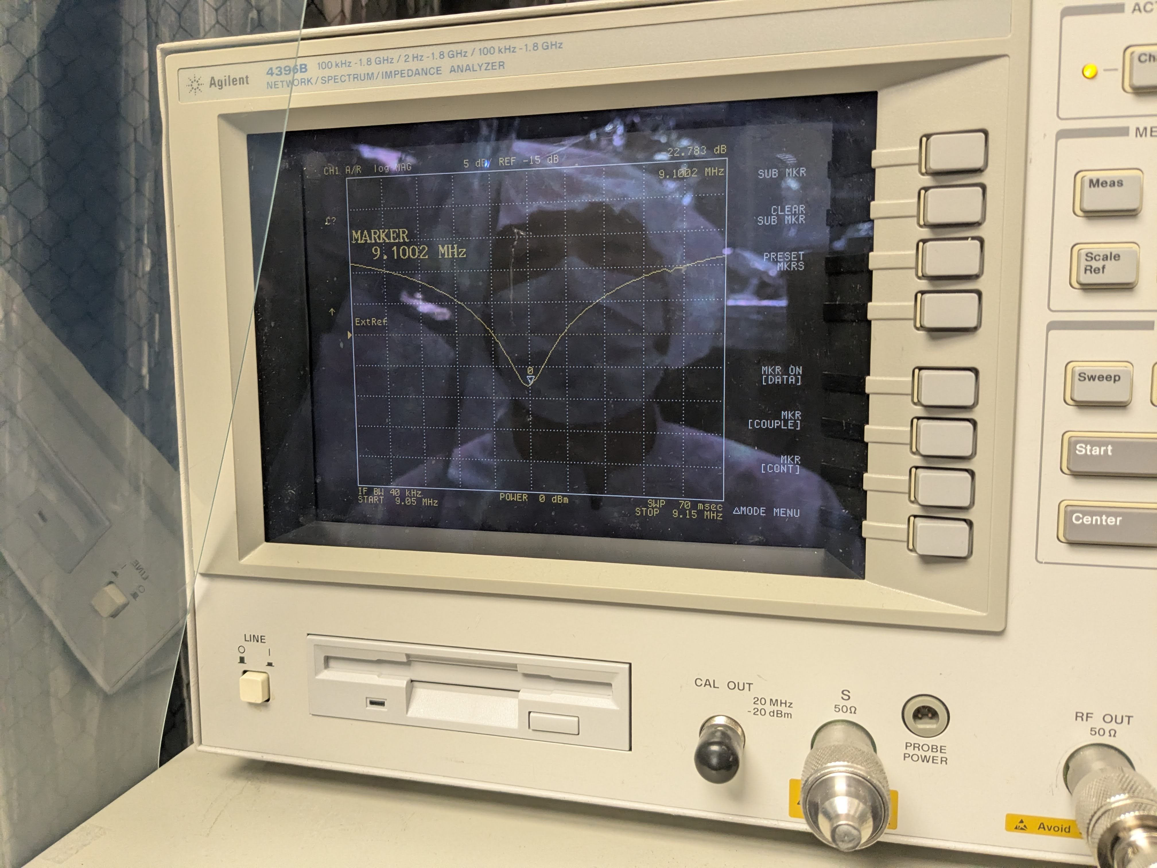
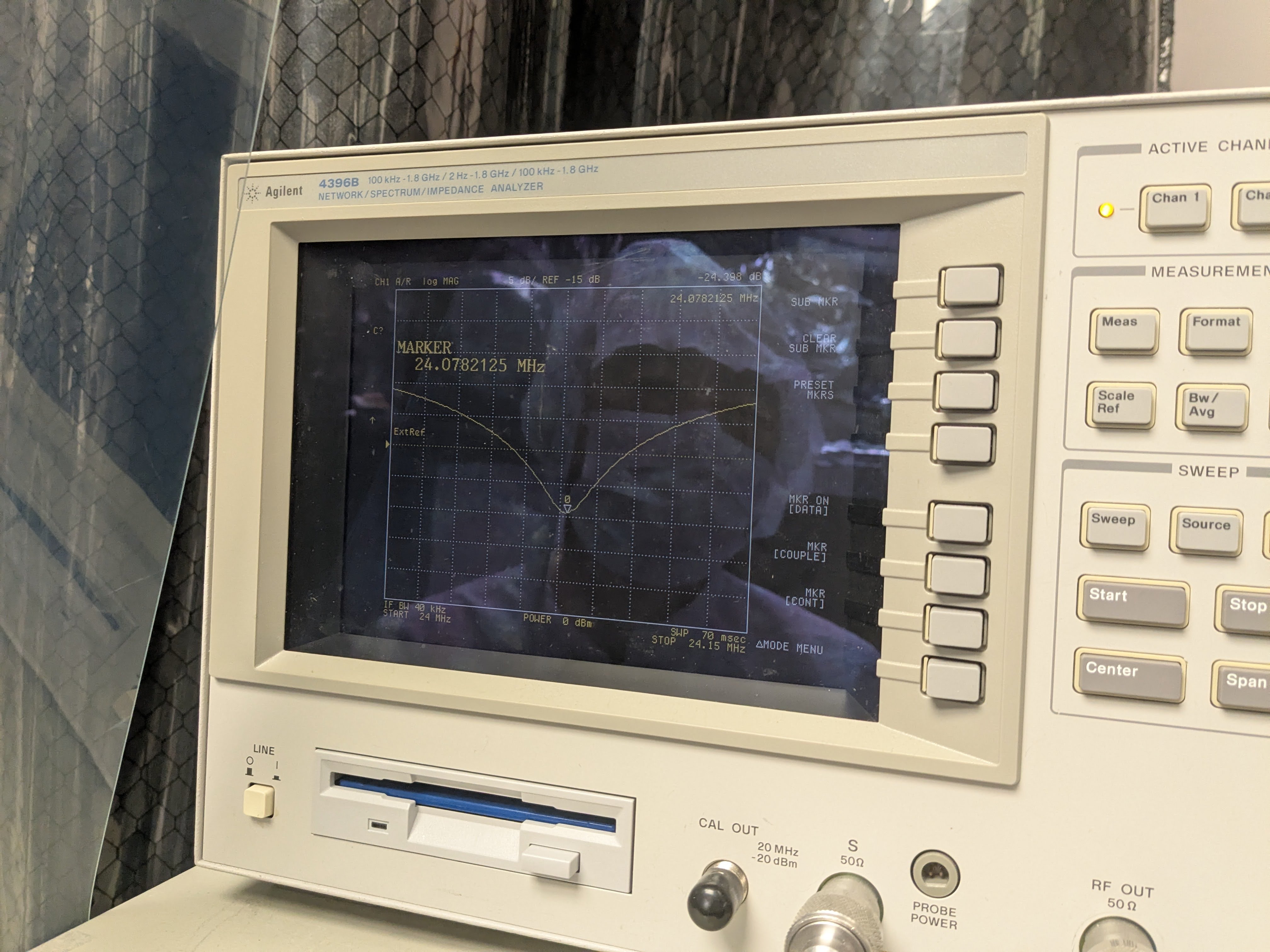
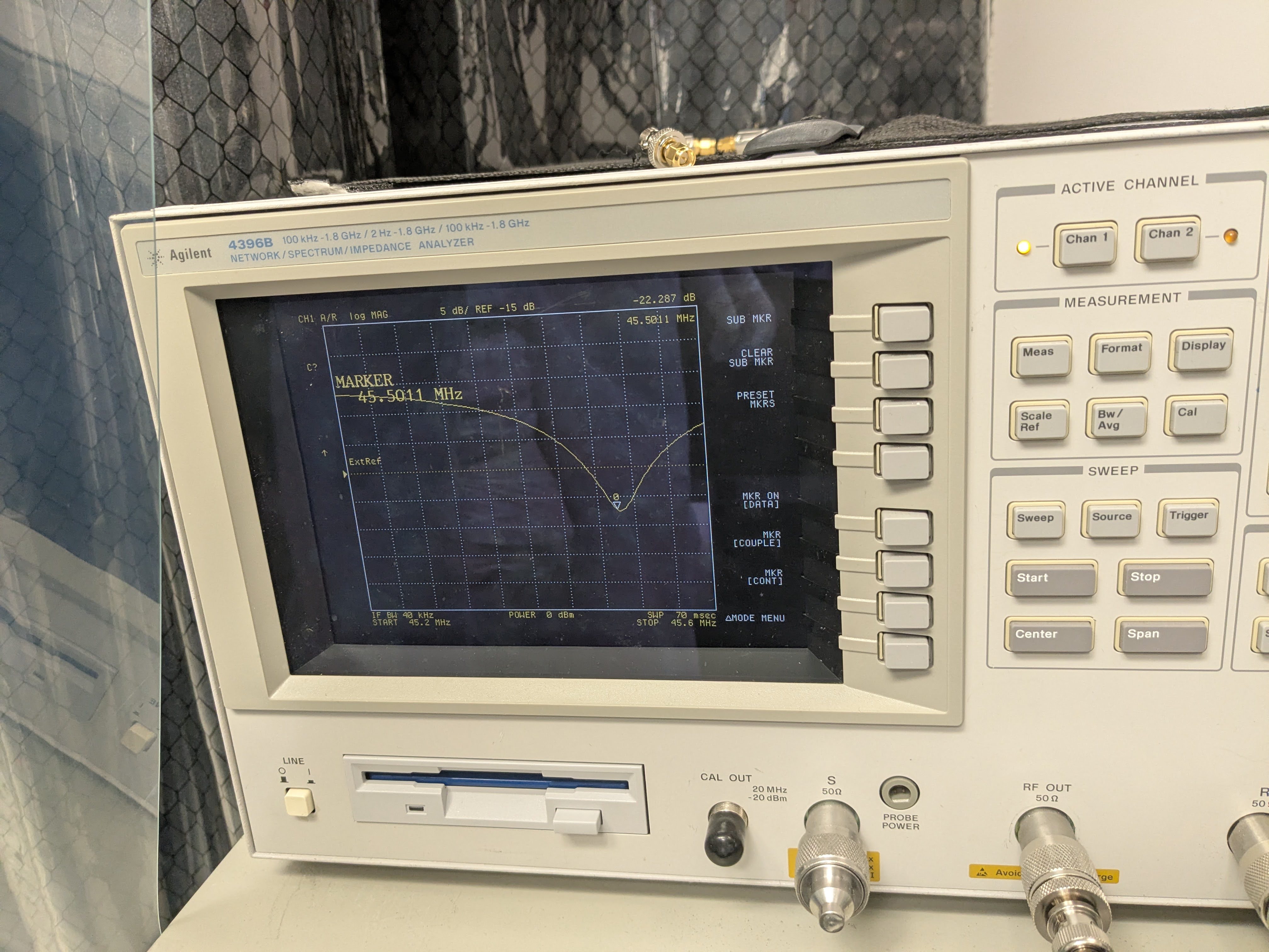
My original concern for the original Appert method (middle of three_methods.png cartoon) was that somehow the screw gets loose during transport or after a large change in the in-chamber temperature and the tuning will be off. Upon hearing this, Stephen proposed a test to loosen one screw and see if the tuning changes. We performed this test for both Stephen method and the in-between method. (Spoiler: yes.) We measured all four dip frequencies right after the alumina piece was mounted but only tracked the frequency change of 118MHz peak.
Loosening one screw changes the frequency, but the frequency change for the in-between method is an order of magnitude smaller (10 to 30kHz) than the original Appert method (300kHz) when the FWHM (or rather the width between the points where reflection is 6dB larger than the bottom of the dip) is about 70kHz or so. This is just one trial but I'm convinced that in-between method (or maybe Laxen method too though we haven't tried) is better, so that's what we'll do for the real crystal.
We only loosened the screws on the output side for both mounting methods.
| |
Initial four frequencies |
Shaking? |
Loosen 1st screw |
Loosen 2nd screw |
| In-between method |
9.142, 24.110, 45.972, somewhat
smaller than 118.214kHz
|
changed to 118.214kHz, unclear why.
(Something like 10k or 20kHz change,
couldn't cause another change by gentle tapping.)
|
118.214 -> 118.240
(+26kHz)
|
118.240 -> 118.251
(+11kHz)
|
| Original Appert method |
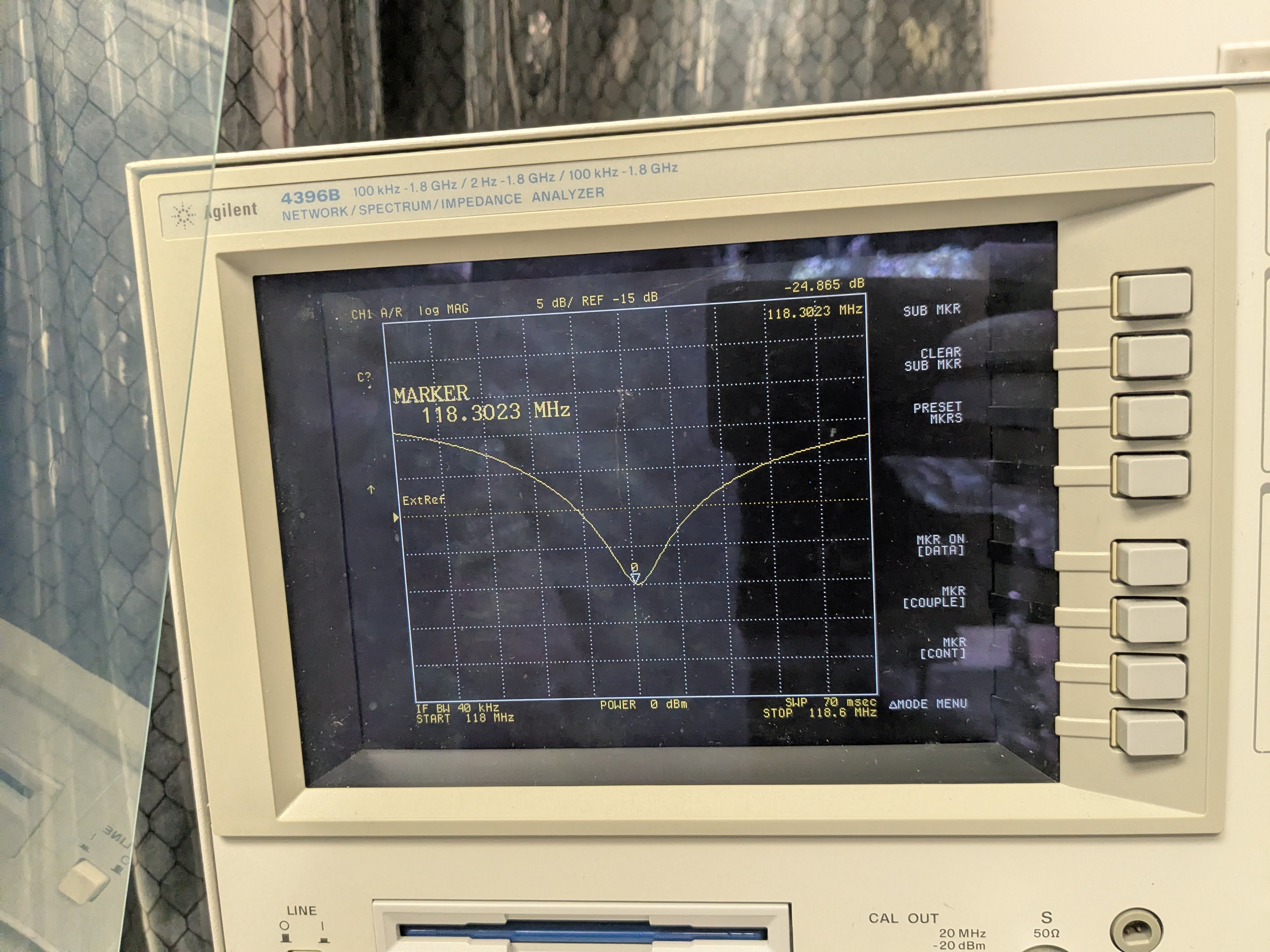
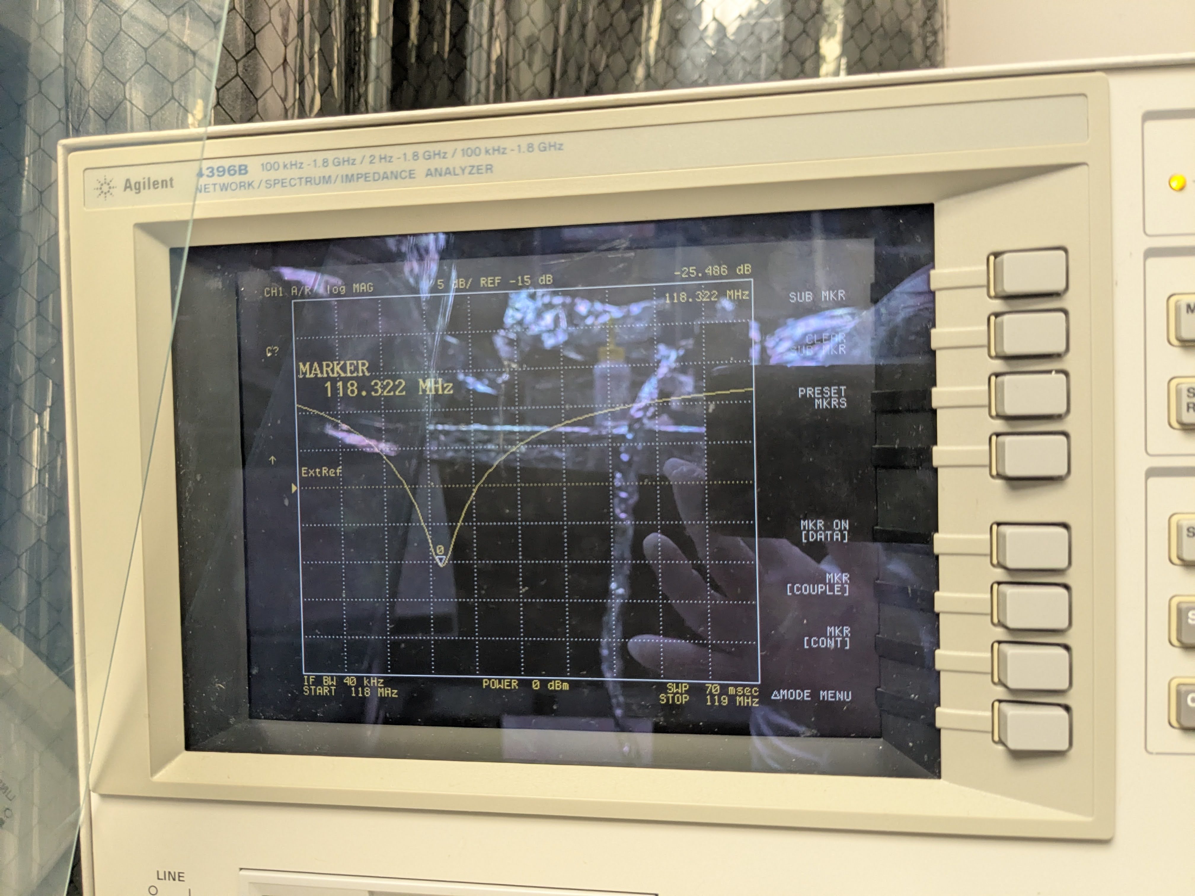
9.14685, 24.107, 46.066, 118.322 |
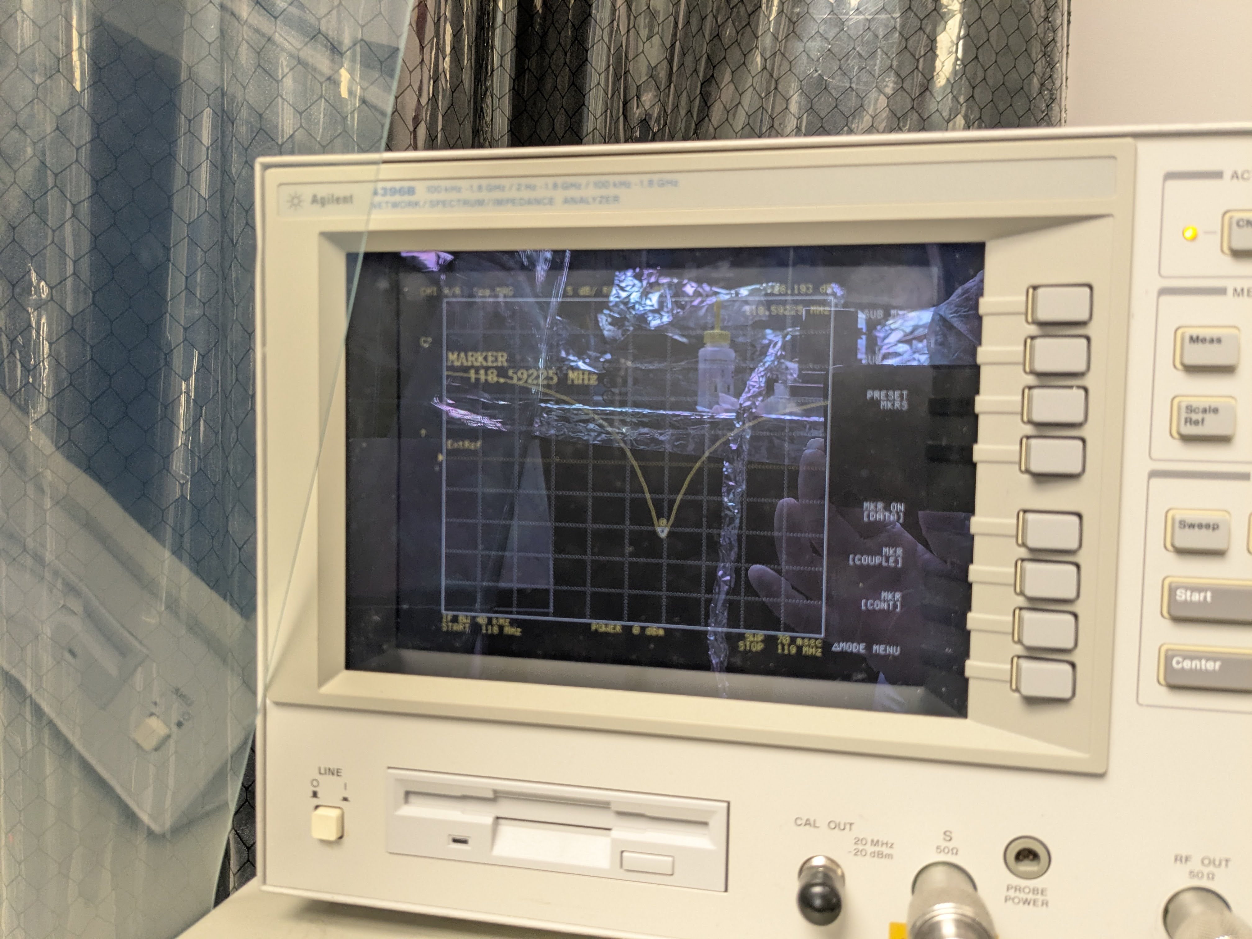
118.322 -> 118.592, caused by gentle tapping.
(+270kHz)
|
118.592 -> 118.876
(+284kHz)
|
118.876 -> noman's land
(>1MHz)
|
Shake and it will shift, we need to measure it again in chamber?
It's good to know that the in-between method can somewhat withstand the loosening of the second screw (because the tighter screws still support the face plate). However, it's disappointing to find that the assembly is susceptible to shaking.
In the in-between method, we couldn't record the initial 118MHz dip because it jumped up by 10kHz or so in front of our eyes when we were moving around the table. Not sure what happened but I assumed that it was some kind of shaking. However, I gently tapped the front and side plates and couldn't cause another shift.
In the original Appert method, since we knew something could happen, I tapped the front and side plates and there was a huge jump. See the difference between initial_118.jpg and taptap_118.jpg.
Even though we'll use in-between mounting method, it's plausible that the frequency shifts during transport or when the EOM lands on the ISI surface. I'm thinking we'll have to measure it in situ after everything is tuned in the lab.
What's to come tomorrow.
We'll install RTP and tune. Before doing that, though, I'll discuss inserting indium foil between the crystal and the front plate with Masayuki. Michael suggested that (and even between the crystal and the electrode, though that would be tricky) today, Masayuki and I talked about the possibility briefly last week, it just sounds like a good thing as a buffer to absorb gaps here and there.
Other things.
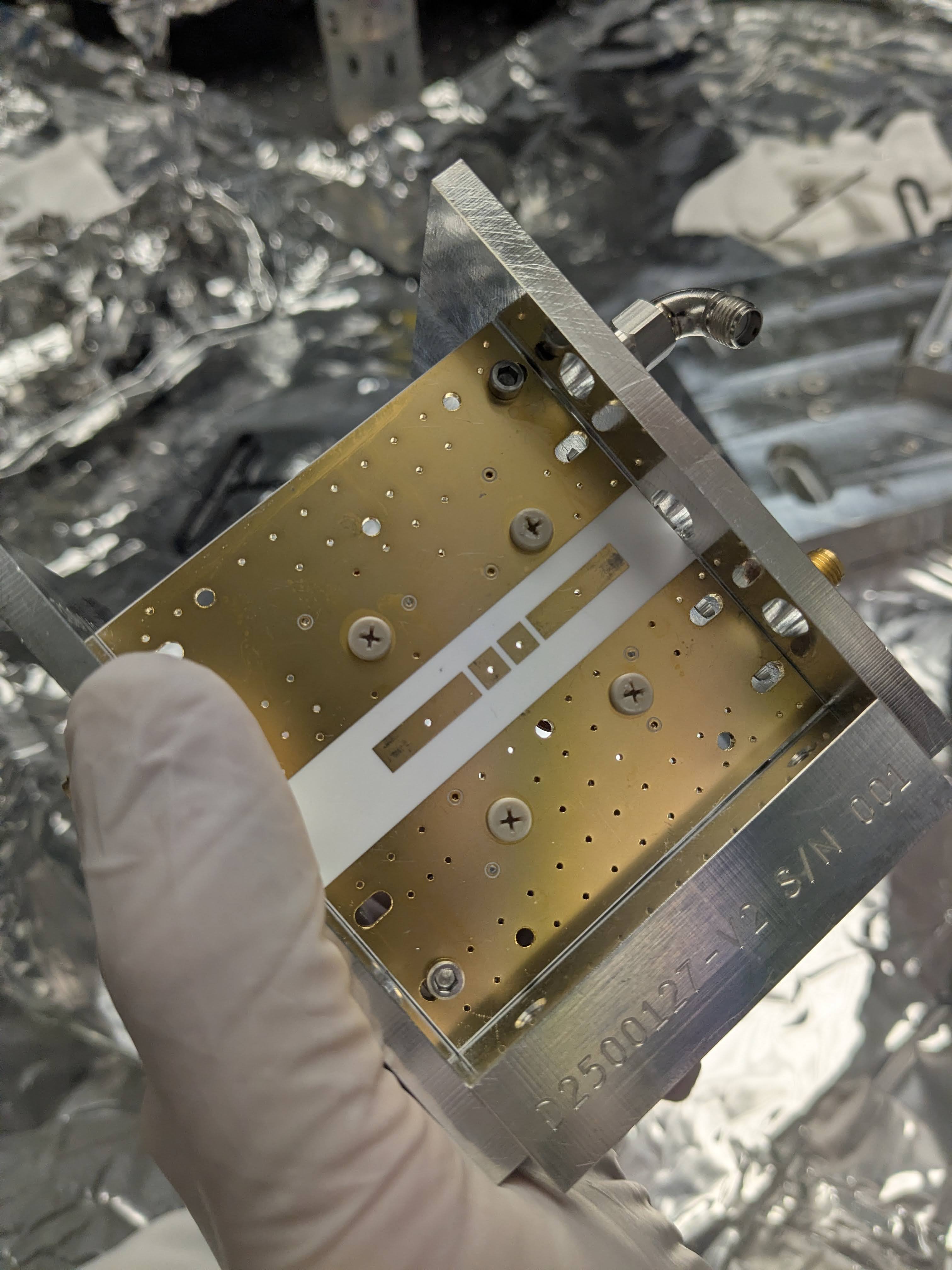
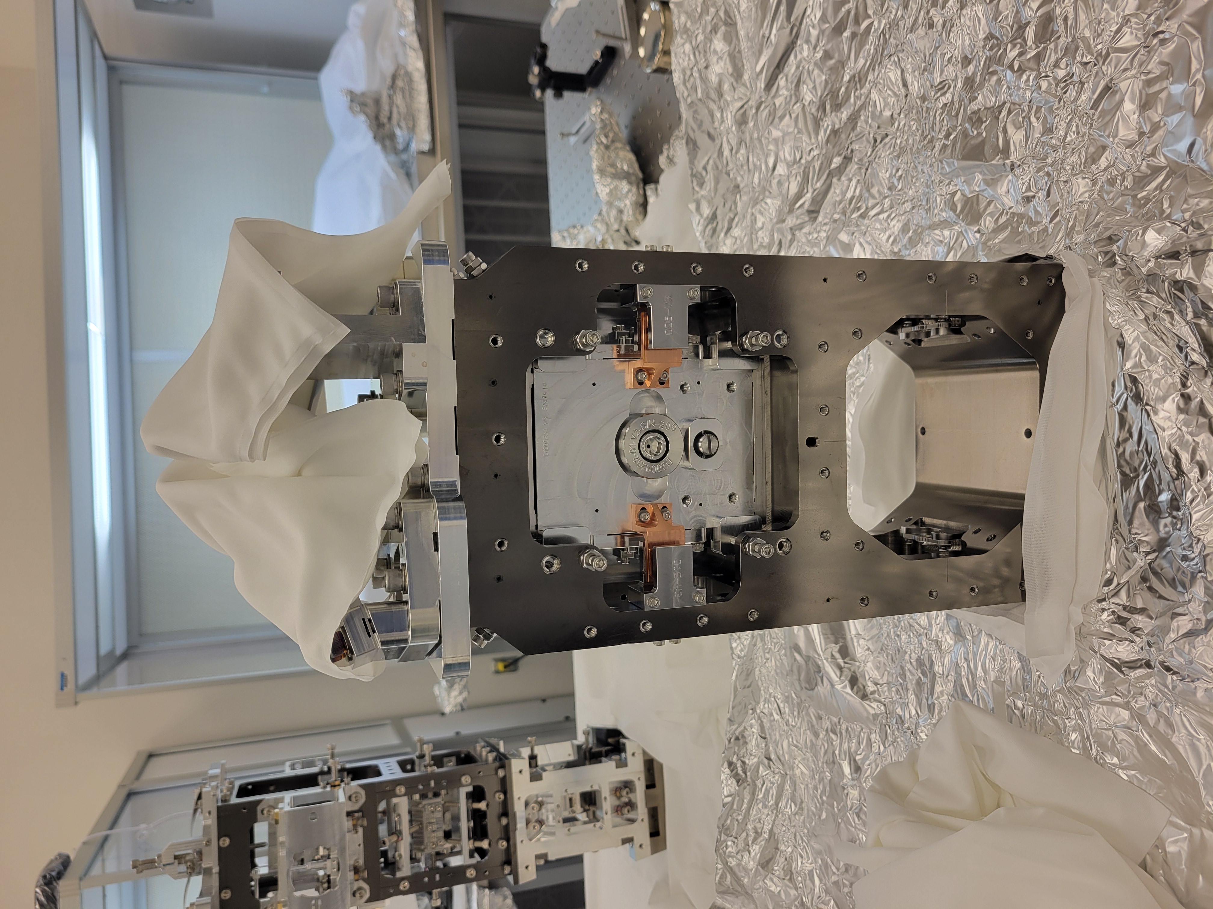
In the previous alog (88886) in one of the pictures (gap.jpg), there was a time when it looked as if the circuit board was slightly bowed. We took a picture of the electrode today (electrode_contactpoint.jpg) and it looks as if the electrode is more abraded close to the outside edge of the crystal, so maybe the board bowing is real.


