ryan.crouch@LIGO.ORG - posted 00:02, Friday 01 September 2023 (72616)
Lockloss at 07:00UTC
We lost lock right at 07:00. not sure why there was a DCPD saturation right before.
We lost lock right at 07:00. not sure why there was a DCPD saturation right before.
TITLE: 09/01 Eve Shift: 23:00-07:00 UTC (16:00-00:00 PST), all times posted in UTC
STATE of H1: Observing at 147Mpc
INCOMING OPERATOR: Austin
SHIFT SUMMARY: Quiet shift, 1 lockloss fairly automated relock, I touched two things. Locked for 1:07 as of 07:00UTC
Lockloss at 04:35UTC
LOG:
No log for this shift
https://ldas-jobs.ligo-wa.caltech.edu/~lockloss/index.cgi?event=1377578169
Reaquired Observing at 06:04UTC
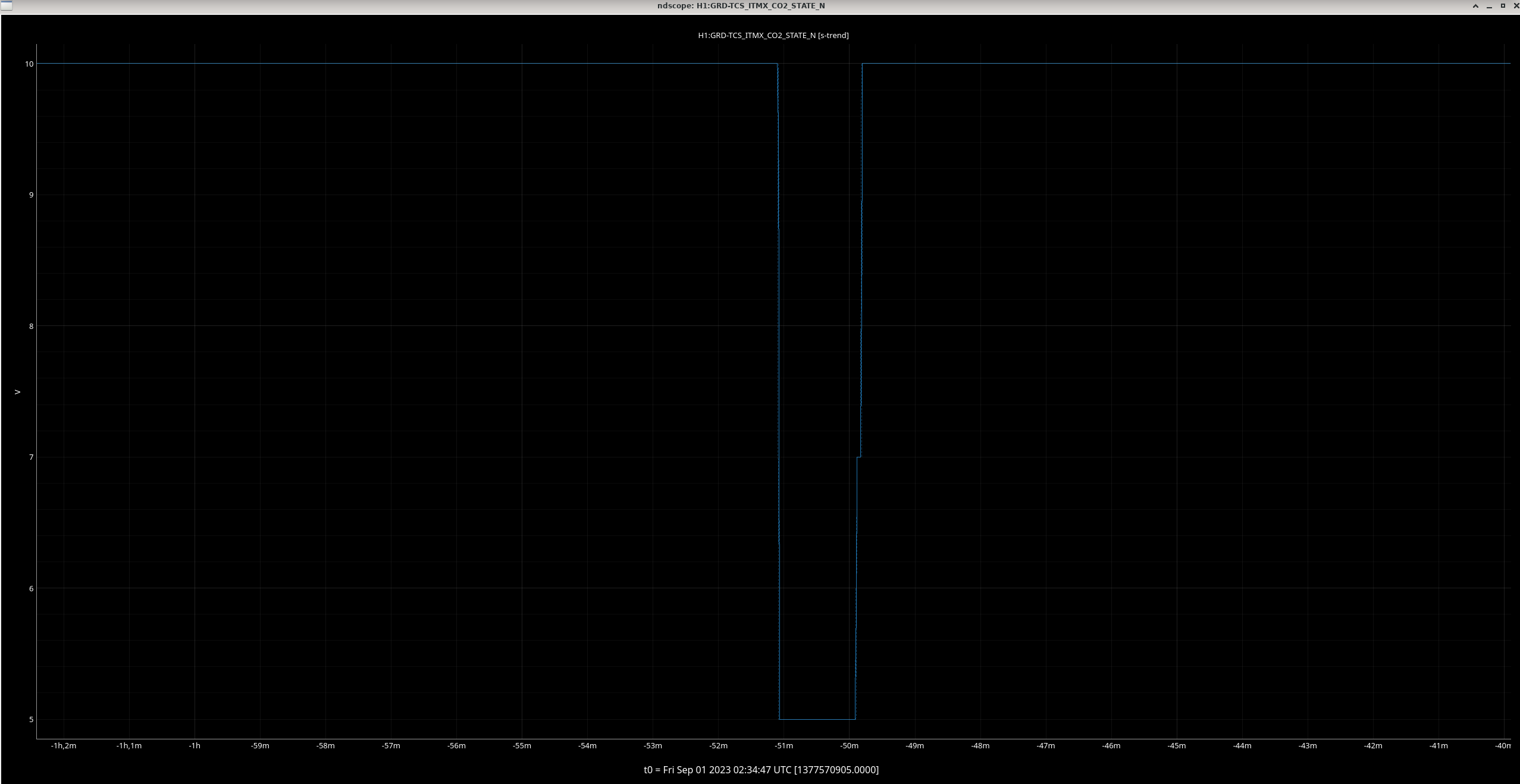
We've been locked for 4:56, everything seems stable. We've been Observing since 22:24 aside from a brief droppout from 1:43 to 1:45UTC from the ITMX CO2 laser relocking.
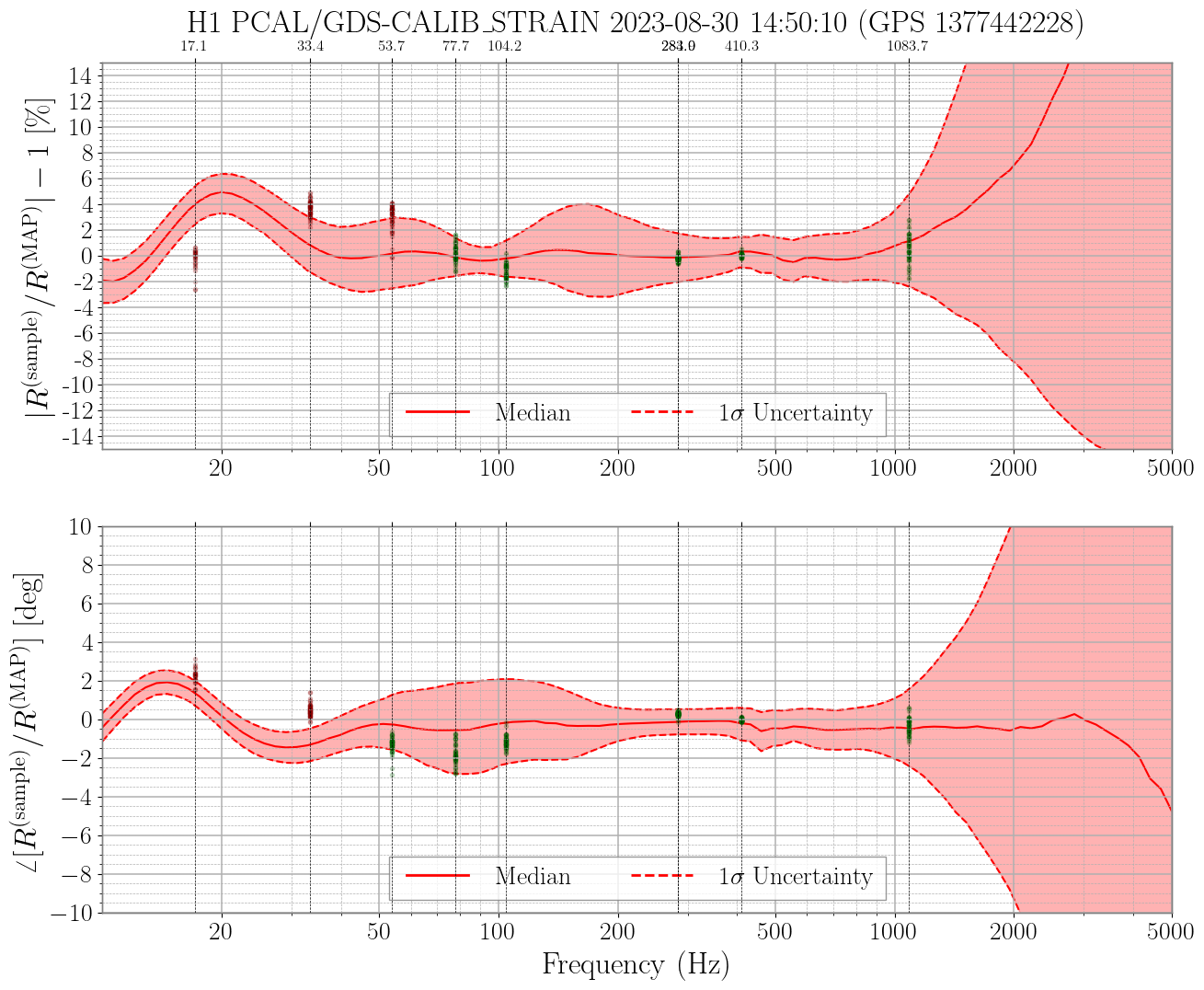
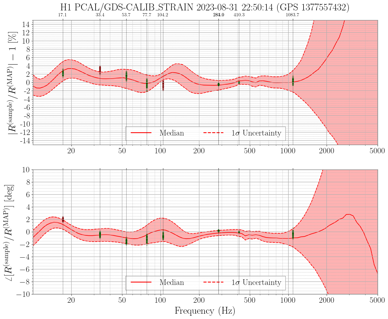
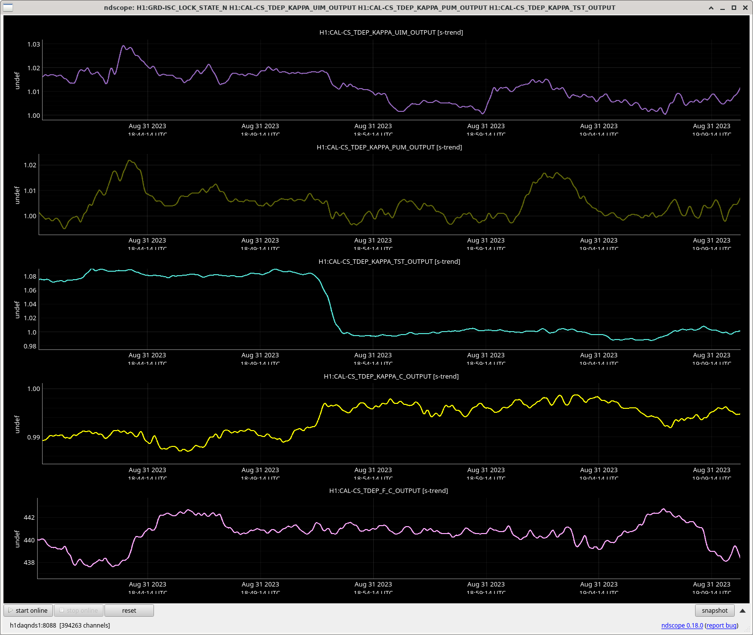
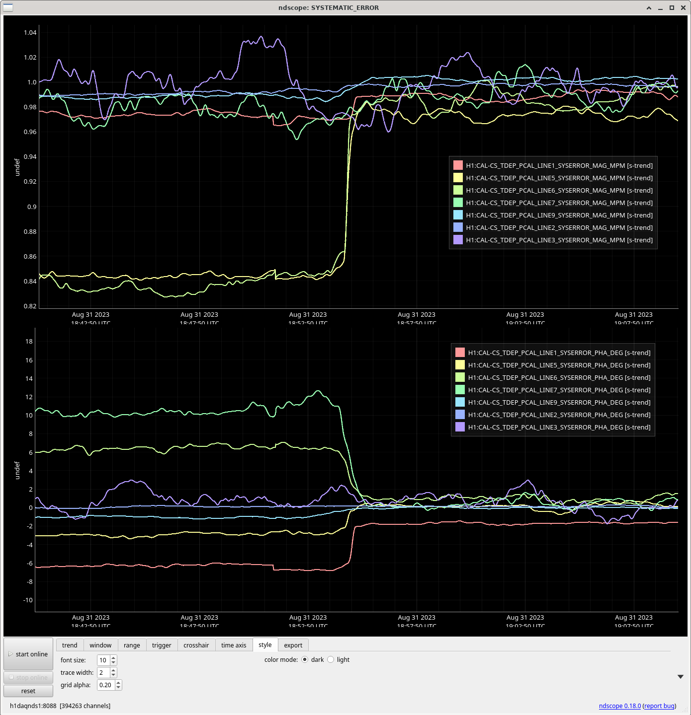
J. Kissel, L. Dartez

After the calibration update today (2023-08-31; LHO:72594) we now have automatically generated comparisons between measured systematic error in the GDS-CALIB_STRAIN channel (as measured directly by PCAL) vs the traditional model of the systematic error. The results look great.

I attach two automated comparisons to highlight the difference:
Before from 1377445828 2023-08-30 15:50 UTC:
   - pre- 2023-08-30 maintenance,
   - pre- DARM2 FM8 boost turn on,
   - \kappa_T is still a 1.08, so DELTAL_EXTERNAL (which isn't corrected for time-dependence) disagrees with GDS-CALIB_STRAIN which does.
   - still not having updated the sensing function since we turned OM2 TSAMS back on
   - the modeled systematic error is still using GPR fits of measured data from 2023-06-21 and prior
vs.
After from 1377561032 2023-08-31 23:50 UTC:
   - post-calibration update
   - DARM2 FM8 boost is accounted for,
   - DELTAL_EXTERNAL and GDS-CALIB_STRAIN agree
   - All TDCFs are close to 1.0
   - Modeled systematic error is now using GPR fits are now using an updated collection of measurements.
As we are gearing up to regenerate our hourly uncertainty estimates spanning back to the start of O4, I needed to go back through the history of LHO calibration changes, the IFO changes they address, and the identification and placement of each new epoch for the sensing and actuation functions. The table below lists the calibration epochs since the start of O4. For each epoch, I include some relevant alogs that chronicle which IFO changes triggered each epoch. More in depth information on each change to the LHO calibration pipeline can be found in the living Record of Real-Time Calibration Pipeline Parameter Changes (DCC: T2300297).
| Date | Epoch Type | Reason for new epoch |
|---|---|---|
| 20230504T055052Z | Sensing, Actuation | new SRCL offset (LHO:69289), TCS changes (LHO:69032), and PCALX cal line change (LHO:69303). More in LHO:69332. This report was *not* exported to the front end. |
| 20230506T182203Z | Sensing | Changed SRCL offset, DARM loop. More in LHO:69561. N.B. This report marks a new epoch for the sensing function but it did not get exported to the front end (i.e. the "calibration" was not updated using this report). Instead, the report that was used to update the calibration and includes the IFO changes listed in LHO:69561 is 20230510T062635Z. |
| 20230621T191615Z | Sensing | Moved back to 60W input power(LHO:70693). 20230621T191615Z marks the start of the epoch but the report used to update the IFO calibration is 20230621T211522Z. |
| 20230628T015112Z | Sensing | OM2 was heated (first time). See LHO:70849. |
| 20230716T034950Z | Sensing | OM2 was unheated. See LHO:72524. |
| 20230727T162112Z | Sensing | OM2 was reheated. See LHO:72523. |
| 20230817T214248Z | Actuation | 3.2kHz filter restored in L3 actuation path. See LHO:72043 |
/ligo/groups/cal/H1/reports/archive/.
06/21 reason: 60W
06/27 14:53 : om2 hot
20230628T015112Z [regenerated for epoch-sensing]
07/12 16:05 : om2 cold
20230716T034950Z [regenerated for epoch-sensing]
07/19 08:15 : om2 hot
20230727T162112Z [regenerated for epoch-sensing]
20230802T000812Z [regenerated for new epoch-sensing]
20230817T214248Z [regenerated for epoch-actuation]
20230823T213958Z [regenerated for new epoch-sensing and new epoch-actuation]
actuation:
05/04: start of O4
08/08: 3.2kHz filter
20230817T214248Z [regenerated for epoch-actuation]
Vicky and I went to SQZT7 while calibration work was happening, to follow up on some of our observations from 72525 (and Vicky's comment).
Polarization issue:
With the seed dither locked, we placed a PBS before the half wave plate in the homodyne sqz path and measured 67.2uW transmitted (vertical pol) and 750uW reflected (horizontal) (817uW total, 8% in the wrong polarization, 16.5 degrees polarization rotation). After the half wave plate we measured 5.48uW transmission through the PBS (vertical) and 802uW reflected (horizontal) ( 807uW total, 0.7% in the wrong polarization, polarization less than 5 degrees away from horizontal). We also placed the PBS right at the bottom of the periscope, and there measured 70uW transmitted and 820uW before the PBS was inserted (8.5% in the wrong polarization, 17 degrees polarization rotation away from horizontal). This would not limit the squeezing measured on the homodyne since we are able to correct it with the HWP, but measuring the same polarization rotation at the bottom of the periscope suggests that the beam could be coming out of HAM7 with this polarization error, which would look like an 8% loss to the squeezing level in the IFO.
In Sept 2022, during the vent for the OM2 swap, we measured the throughput of the seed beam from HAM7 to HAM6 65110, which agreed well with the only loss between HAM7 and HAM6 being the 65.6% reflectivity of SRM, and suggests that there was not an 8% loss in the OFI at that time.
Loss on SQZT7 (not bad):
Comparing the total power measurements here, we have 820uW at the bottom of the periscope, and 807uW measured right before the homodyne, so we have something like 1.6% loss on SQZT7 optics (small compared to the type of loss we need to explain our squeezing level).
Seed transmitted power over reflected power ratio has dropped:
We also measured the seed power reflected from the OPO, so that we could compare the ratio of transmitted to reflected seed measured at the time of the squeezer installation in HAM7 in Feb 2022: 61904 (3.9% trans/refl). Today we saw 0.82mW seed transmitted, and 27mW of reflected seed at the bottom of the periscopes (3.03% trans/refl). This is 78% of the ratio measured at installation. Because this seems like a large drop, we repeated the measurement twice more, and got 3% each time. We also checked that the dither lock is locking at the maximum seed transmission.
Homodyne PD QE check (QE of PDB might be low):
We used an Ophir which was calibrated in 2018 to measure the LO power onto the homodyne PDs, the filter and head are SN 889882 and the controller is SN 889428. For PDA we saw 0.6mW, for PDB we saw 0.63mW.
Both the PDs are calibrated into mA in the front end, which includes anti-gain of gain(0.25)gain(0.22027), transimpedance of 0.001 (1kOhm), two anti-whitening filters (and cnts2V and mA factors). For PDA there is a fudge factor in the filter gain, if we divide this out, the readback is that the PDA photocurrent was 0.512mA, and 0.5126mA for PDB (with a drift of 0.5% over the measurement time). This gives a responsivity of 0.855A/W for PDA and 0.813A/W for PDB. For QE of 1, the responsivity would be e lambda/(h c) = 0.8582 A/W, so our measurement is 99.6% QE of PDA, and 95% QE for PDB. (See Vicky measured higher reflection off PDB than PDA in 63893 and Haocuns' measurement in 43452).
Above I mixed up vertical and horizontal polarization. The LO beam arriving at the homodyne is vertically polarized, as well as the seed beam coming out of the chamber.
Revisiting old alogs about the seed refl/trans (throughput) measurement:
In the first installation Feb 2022, The refl/trans ratio was measured as 4% Feb 24th 61904, and the ratio of IR trans arriving on SQZT7 to right after the OPO was 95% measured Feb 10th 61698
When the CLF fiber was swapped this measurement was redone: 64272 There we didn't measure CLF refl, but combining the measurements of 37mW out of fiber and 8mW rejected we can expect 29mW CLF refl. With 0.81mW reaching HAM7 this was a 2.8% ratio of refl/trans. This is worse than at the inital installation but similar to what Vicky and I measured last week. But, this alog also indicated 95% transmission from right out of the OPO to SQZT7. So this second measurement is consistent with the one we made last week, and would indicate no excess losses in HAM7 compared to that time.
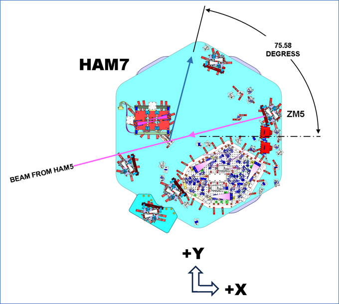
Polarization rotation is only an on-table problem for SQZT7, not an issue for IFO. It can be attributed to the SQZT7 persicope. To close the loop, see LHO:73537 for Don's latest CAD layout with the squeezer beam going to SQZT7 at a 14.4 degree angle (90-75.58) from +Y. SQZT7 periscope re-directs the beam to travel basically along +Y.
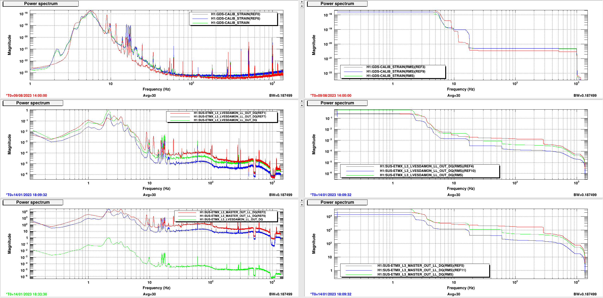
Sheila had been looking at biasing back in January (66814) and wanted to make some comparisons from then and now for the RMS drive to the ESD. Plots from observing on Aug 9 vs biasing changes from Jan 14. These are the "ADS lines on" times from the alog referenced. Reference times shown on leftmost plots.
Jan 14 18:09:32 Full Bias (Blue)
Jan 14 18:33:20 1/4 Bias (Green)
Aug 8 14:00:00 Full Bias (Red)
The LSC feedforward, and in particular the MICH feedforward, has needed regular updating since we reduced the IFO input power to 60W in June. I wrote up a summary of the "saga" as of the start of August, see 72037. My main assumption was this: ignoring major IFO changes such as input power/TCS/DARM offset, the changes to the feedforward have to occur because we "uncover" more and more LSC coupling as we improve the low frequency sensitivity. To justify this idea, I referenced the fact that Gabriele and I (except for the first retuning on June 22 with the power reduction) have mainly been doing iterative retuning of the feedforward. Specifically, we run our "retuning" injection with the feedforward on so that the noise coupling we attempt to reduce is any residual noise coupling left over while our main feedforward runs. However, since that alog we have again needed to update the MICH feedforward multiple times without any corresponding improvement to low frequency sensitivity, finally prompting me to think that something here is wrong. However, it is not a significant change in the feedforward from time to time, but merely a few percent change that we iteratively improve against some baseline decent feedforward.
Gabriele and I have found evidence that the MICH coupling to DARM is changing because the ETMX test mass actuation strength has been changing from ESD charge accumulation. Jeff details the effect of this charge accumulation on the calibration in LHO:72416, and has some notes about seeing this effect in the past, effects on the DARM loop, etc.
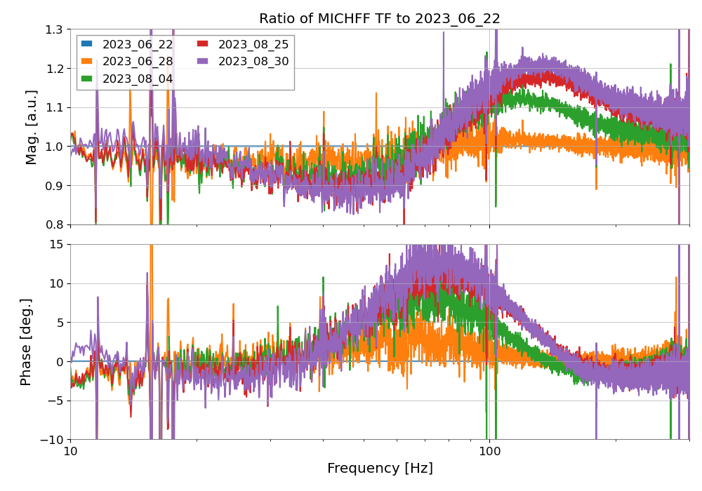
This change in the test mass actuation can also change the coupling function for the LSC noise contribution. In particular, when we measure the coupling of MICH for the feedforward fitting, we measure two functions. One is the DARM [W] / MICH [N] coupling, and the other is the DARM [W] / DARM [N] coupling. The changing strength of the DARM actuation will effect the required strength of the feedforward actuation. In fact, looking at the filters we have tuned for the MICH feedforward in August, they all have the same shape, but different overall gains.
We make a measurement of the second function above by injecting from the MICHFF filter bank with the input off and the feedforward filter off (but a gain of 1), so we can capture whatever effect is upstream of the feedforward filter banks. Gabriele plotted all of these measurements that we have taken since June 22 and normalized them by the June 22 measurement. The result is shown in the first image attached. This plot shows that the DARM actuation is changing in the same direction over time. We also tracked the Kappa TST value, and noticed that is has been steadily increasing since June 22.
This effect is most visible in the MICH coupling, and we have needed to update the MICH feedforward iteratively more than we have the SRCL feedforward. We think this is because the subtraction of MICH is much more significant than the subtraction of SRCL, by at least a factor of 5. Looking at the implemented SRCL feedforward since June 22, a similar change in gain is evident. The bigger changes in the SRCL shape have been mostly at low frequency to reduce injection of excess SRCL actuation noise into DARM which worsens the DARM RMS.
We predict that as the test mass actuation strength changes, we will continue to need to update the feedforward to improve the subtraction of noise and reach our best possible sensitivity. The MICH feedforward was updated yesterday, Aug 30, and the calibration has been updated today, resetting Kappa TST to 1 (72594). We should track the Kappa TST value. If it becomes even a few percent different than 1, Gabriele and I imagine we will need to make another iterative update to the feedforward.
While we think the few percent change in actuation explains most of the few percent change in the MICH coupling, there could be other changing factors. We have been tracking possible alignment changes in the interferometer related to OM2 TSAMS changes, unexpected temperature changes, etc. Changing IFO alignment could also contribute to some of the changing LSC coupling we have witnessed (although the how of this process is less clear to me). If we manage to mitigate the charge accumulation on ETMX, we should continue to track the MICH coupling in case there are other effects that compromise the success of the noise subtraction.
TITLE: 08/31 Day Shift: 15:00-23:00 UTC (08:00-16:00 PST), all times posted in UTC
STATE of H1: Observing at 146Mpc
INCOMING OPERATOR: Ryan C
SHIFT SUMMARY: One lock loss during the shift that ended a 27 hour lock. Relocking was straight forward but I had to very slightly move ETMY to get ALSY to lock. This was the only locking intervention (outside of a small test). We've now been locked for 1 hour and observing for 45min.
LOG:
| Start Time | System | Name | Location | Lazer_Haz | Task | Time End |
|---|---|---|---|---|---|---|
| 15:13 | FAC | Randy | MY | n | Inventory | 18:47 |
| 15:51 | FAC | Ken | OSB receiving | n | Replacing lights | 22:07 |
| 17:30 | FAC | Tyler | EY | n | Chiller line work on top of air handler roon | 18:07 |
| 17:32 | CC/SEI | Mitch | EY, EX | n | FAMIS checks in end station mech rooms | 18:17 |
| 18:41 | SQZ | Sheila, Vicky | LVEA - SQZ bay | Local | SQZ table alignment | 19:51 |
| 18:41 | CAL | Jeff, Louis | CR | n | CAL measurement | 19:57 |
| 19:03 | SEI | Jim | Office | n | HAM1 filter tests | 19:58 |
| 20:00 | FAC | Tyler | EY | n | More HVAC work on AUR | 20:31 |
| 21:22 | SEI | Jim | Office | n | HAM7 new filters | 21:40 |
TITLE: 08/31 Eve Shift: 23:00-07:00 UTC (16:00-00:00 PST), all times posted in UTC
STATE of H1: Observing at 148Mpc
OUTGOING OPERATOR: TJ
CURRENT ENVIRONMENT:
SEI_ENV state: CALM
Wind: 9mph Gusts, 7mph 5min avg
Primary useism: 0.02 μm/s
Secondary useism: 0.18 μm/s
QUICK SUMMARY:
We dropped out of Observing briefly due to the 2 diffs from TCS ITMX_CO2 lasers from 01:43 to 1:45UTC
The FMCS team has their own set of alarms for the reverse osmosis (RO) system. I've removed this alarm in the Alarm Handler system in the control room. Operators will no longer need to alert the FMCS team of RO related issues unless there are major problems.
The file for this is symlinked in /opt/rtcds/lho/h1/alh/fmcs/ to /opt/rtcds/userapps/release/cds/h1/alarmfiles/fmcs.alhConfig and is under svn control.
4 pressure gauges were replaced today after the previous set was damaged during the runaway of EY Chiller 1. (2 per supply and return line)

There is some ambiguity between most of these gauges across all AHU's. Because the new gauges all read nearly exact pressures I will likely replace most/all others in the near future.

I also observed about 10psi of pressure loss since replenishing on friday. Glycol was added via the makeup tank to get back to a 30psi operating pressure. The EY makeup tank now has about 50% capacity.

T. Guidry
2053 Lock loss (1377550449) after exactly 27 hours. No immediate cause.
L. Dartez, J. Kissel

More details to come, but as of 2023-08-31 19:10:00 UTC (12:10 PDT), we've updated several corners of the calibration for the first time since Jun 21 2023 (see LHO:70693) in order to:
    - Update the static model of the test mass actuation strength, to better match the current time-dependent-correction factor value (because it had gotten large enough that approximations used in all TDCF calculations would have started to breakdown) (LHO:72416)
    - Update the "DARM loop modeled transfer functions at calibration line frequencies" EPICs records in order to account for the new DARM2 FM8 boost (LHO:72562 and LHO:72569)
    - Update the sensing function (only a little bit) because we're now regularly operating with OM2 "hot" as of 2023-07-19 (LHO:72523)
    - start using the newly re-organized pydarm librarianship, including the use of new simulines-measured IFO sening and actuation function data. (aLOG pending)
    - fixed an unimpactful bug in the front-end computed version of the live measured response function systematic error, in which the local oscillator frequency for the demod that was demodulating the recently changed 102.13 to 104.23 Hz calibration had not been updated. (to be commented below)

The exciting news is that, with all the metrics we have on hand, these calibration updates made everything better.
    - 1st attachment: at the boundary of the change, we see the "relative" time-dependent correction factors change rapidly from non-unity values to unity values (and the cavity pole doesn't change, as expected).
    - 2nd attachment: at the boundary of the change, we see the front-end computed live measured response function systematic error goes from large values to values close to unity magnitude and zero phase.

We're still tracking down some bugs in the *modeled* systematic error budget that has been broken since yesterday, Aug 20 2023 19:50 UTC *and* we're not sure if the *GDS* processed live measured response function systematic error is running yet, but we'll keep you posted.

The comments below will also contain some updated details on the process for this update.
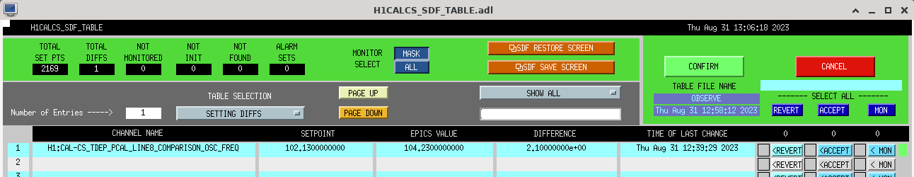
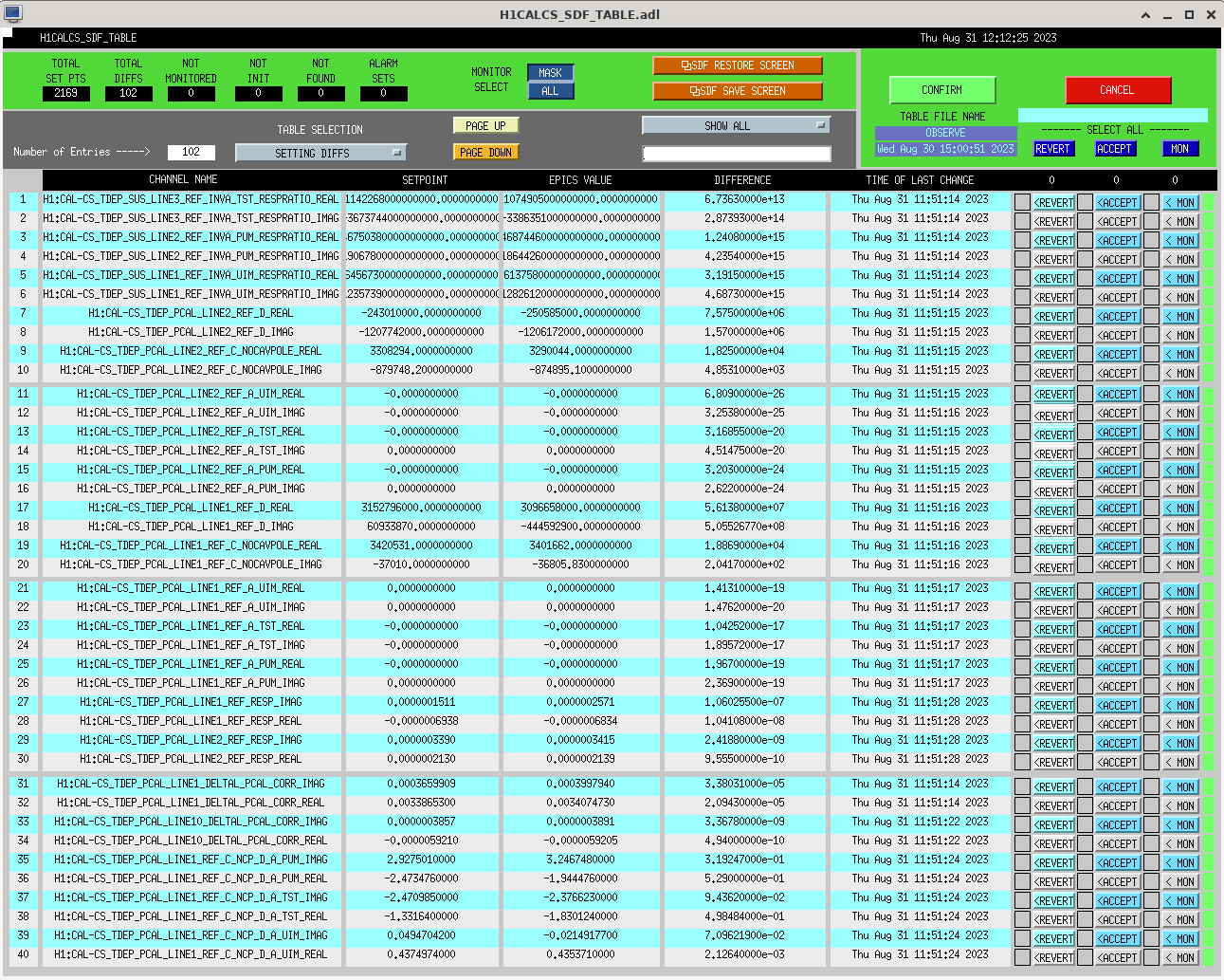
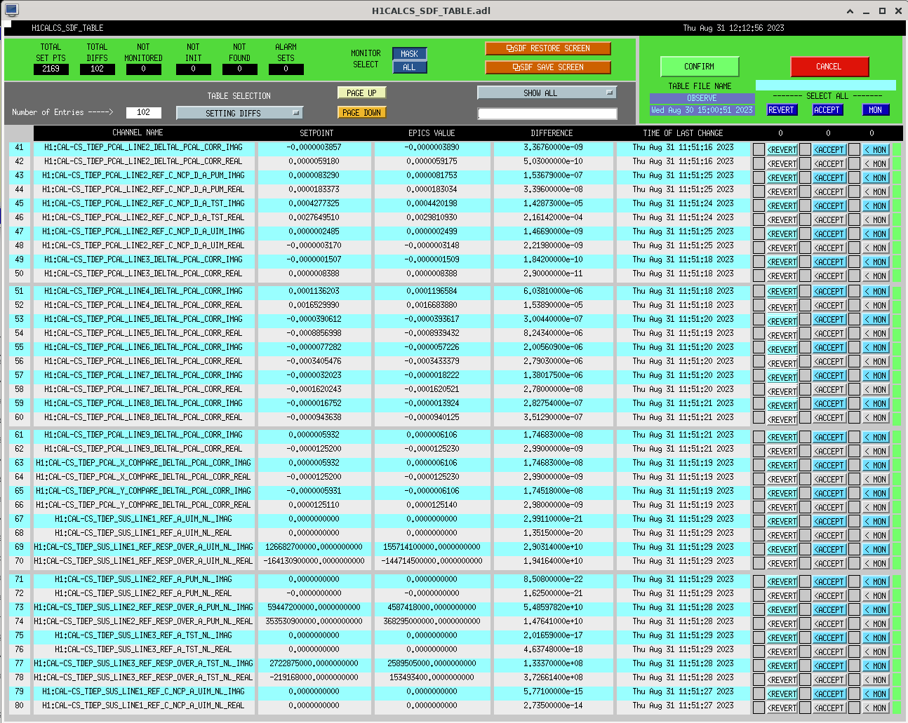
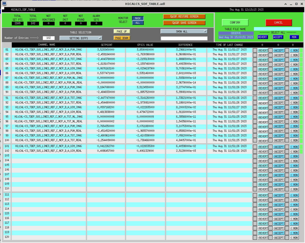
attaching SDF tables for the cal update and for the H1:CAL-CS_TDEP_PCAL_LINE8_COMPARISON_OSC_FREQ change. All changes have been accepted and saved on OBSERVE and safe snap files.

I'm also including a screenshot of the H1CALCS filter updates (H1CALCS_DIFF.png).
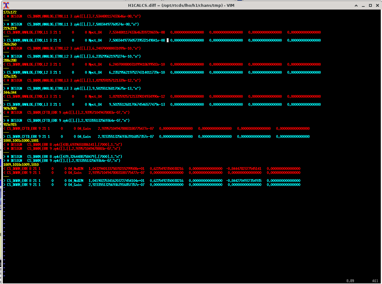
The interferometric-measurement-informed portion of this calibration push was informed by report 20230830T213653Z, whose measurement is from LHO:72573.


    parameter         foton value       physical units value
    -----------       -------------     -----------------------
    1/Hc  [m/ct]      2.93957e-07       3.4019e+06  [ct/m]    (* 2475726 [mA/ct] * 1e-12 [m/pm] = 8.422 [mA/pm])
    f_CC   [Hz]        438.694

    L1/EX [N/ct]      7.53448e-08       1.60487     [N/A]
    L2/EX [N/ct]      6.24070e-10       0.03047     [N/A]
    L3/EX [N/ct]      1.02926e-12       2.71670e-11 [N/V^2]   (with 3.3 [DAC V_bias] * 40 [ESD V_bias / DAC V_bias] = 132 [ESD V_bias])
I attach here a log of the process for updating the calibration.

A lot of the work is much like it was in June -- see LHO:70735, but there are a few new bells and whistles that we used. Plus, there's a few extra steps at the end to validate that down-stream products look good -- namely, that the end-game plot -- the *measured* and *modeled* systematic error agree from https://ldas-jobs.ligo-wa.caltech.edu/~cal/. Indeed, in doing this, we found some bugs that we're still sorting out.

I also note that Louis did a TON of work leading up to today, generating the last ~2 months of reports, re-organizing and re-creating them, defining epoch tags, etc. So steps (0) through (5) were taken care of before today, and we started around step (6).

Steps (6)-(9) out of (11) -- using today's procedure's numbering -- worked really well, and went super smoothly. The procedure is getting quite good!
Elenna, Gabriele, Camilla
This afternoon we updated the MICH Feedforward, it is now back to around the level it was last Friday, comparison attached. Last done in 72430. Maybe need to be done so soon because of the 72497 alignment changes on Friday.
The code for excitations and analysis has been moved to /opt/rtcds/userapps/release/lsc/h1/scripts/feedforward/
Elenna updated in guardian to engage FM1 rather than FM9 and sdf accepted. New filter attached. I forgot the accept this in h1lsc safe.snap and will ask the operators to accept MICHFF FM1 when we loose lock or come out of observe(72431), tagging OpsInfo.
Attached is a README file with instructions.


Accepted FM1 in the LSC safe.snap
Calling out a line from the above README instructions that Jenne pointed me to that confirms my suspicions that the *reason* the bad FF filter's high Q feature showed up at 102.128888 Hz, right next to the 102.13 Hz calibration line:
    "IFO in Commissioning mode with Calibration Lines off (to avoid artifacts like in alog#72537)."

in other words -- go to NLN_CAL_MEAS to turn off all calibration lines before taking active measurements that inform any LSC feed forward filter design.

Elenna says the same thing -- quoting the paragraph from LHO:72537 later added in edit:

How can we avoid this problem in the future? This feature is likely an artifact of running the injection to measure the feedforward with the calibration lines on, so a spurious feature right at the calibration line appeared in the fit. Since it is so narrow, it required incredibly fine resolution to see it in the plot. For example, Gabriele and I had to bode plot in foton from 100 to 105 Hz with 10000 points to see the feature. However, this feature is incredibly evident just by inspecting the zpk of the filter, especially if you use the "mag/Q" of foton and look for the poles and zeros with a Q of 3e5 (!!). If we ensure to both run the feedforward injection with cal lines off and/or do a better job of checking our work after we produce a fit, we can avoid this problem.
Vicky, Naoki, Sheila, Daniel
Details of homodyne measurement:
This morning Daniel and Vicky reverted the cable change to allow us to lock the local oscillator loop on the homodyne (undoing change described in 69013). Vicky then locked the OPO on the seed using the dither lock, and increased the power into the seed fiber to 75mW (it can't go above 100mW for the safety of the fiber switch). We then reduced the LO power so that the seed and LO power were matched on PDA, and adjusted the alignment of the sqz path to get good (~97%) visibility measured on PDA. We removed the half wave plate from the seed path, without adjusting the rotation. With it removed, we checked the visibility on PDB, and saw that the powers were imbalanced.
Polarization issue (revisiting the polarization of sqz beam, same conclusion as previous work):
There is a PBS in the LO path close to the homodyne, so we believe that the polarization should be set to horizontal at the beamsplitter in that path. The LO power on the two PDs is balanced (imbalanced by 0.4%), so we believe this means that the beamsplitter angle was set correctly for p polarized light as we found it, and there is no need to adjut the beamsplitter angle. However, when we switched to the seed power, there is a 10% difference between the power on the two PDs without the halfwave plate in the path. We put the halfwave plate back, and the powers were again balanced (with the HWP angle as we found it). We believe this means that the polarization of the sqz path is not horizontal arriving at the homodyne, and that the half wave plate is restoring the polarization to horizontal. If the polarization rotation is happening on SQZT7, the half wave plate should be able to mitigate the problem, if it's happening in HAM7 it will look like a loss for squeezing in the IFO. Vicky re-adjusted the alignment of the sqz path after we put the HWP back in, because it slightly shifts the alignment. After this the visibility measured on PDA is 95.7% (efficiency of 91.6%) and on PDB visibility is 96.9% (efficiency of 93.9%).
SQZ measurements, unclipping:
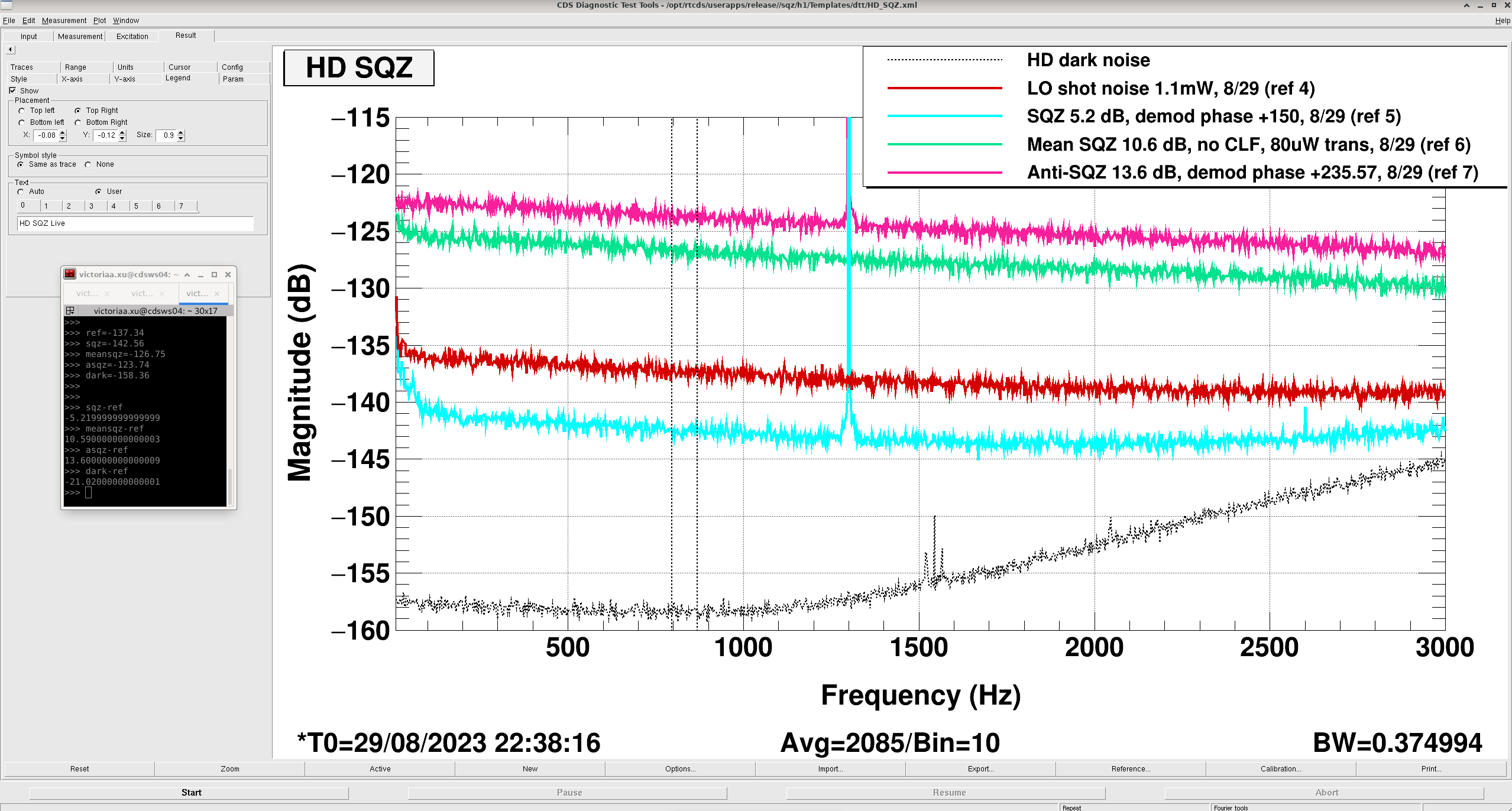
While the IFO was relocking Vicky and Naoki measured SQZ, SN, ASQZ and mean SQZ on the homodyne and found 4.46dB sqz, 10.4dB mean sqz and 13.14dB anti-sqz measured from 500-550Hz. Vicky then checked for clipping, and saw some evidence of small clipping (order 1% clipping with 10urad yaw dither on ZM2). We went to the table to check that the problem wasn't in the path to the IR PD and camera, we adjusted the angle of the 50/50 beamsplitter that sends light to the camera, and set the angle of the camera to be more normal to the PD path. This improved the image quality on the camera. Vicky moved ZM3 to reduce the clipping seen by the IR PD slightly. She restored good visibility by maximizing the ADF, and also adjusted both PSAMs, moving ZM4 from 100V to 95V. (We use different PSAMs for the homodyne than the IFO). After this, she re-measured sqz at 800-850Hz: 5.2dB sqz, 13.6dB anti-sqz, and 10.6dB mean sqz.
Using the nonlinear gain of 11 (Naoki and Vicky checked it's calibration yesterday), and the equations from aoki, this sqz/asqz level implies total efficiency of 0.72 without phase noise, the mean sqz measurement implies a total efficiency of 0.704. From the sqz loss spreadsheet we have 6.13% known HAM7 losses, if we also use the lower visibility measured using PDA we should have a total efficiency for the homodyne of 0.916*0.9387 = 0.86. This means that we would infer an extra 16-18% losses from these homodyne measurements, which seems too large for homodyne PD QE and optics losses in the path. Since we believe that the polarization issue is reflected in the visibility, this means that these are extra losses in addition to any losses the IFO sees due to the polarization issue.
Screenshot from Vicky shows the measurement made including the dark noise.
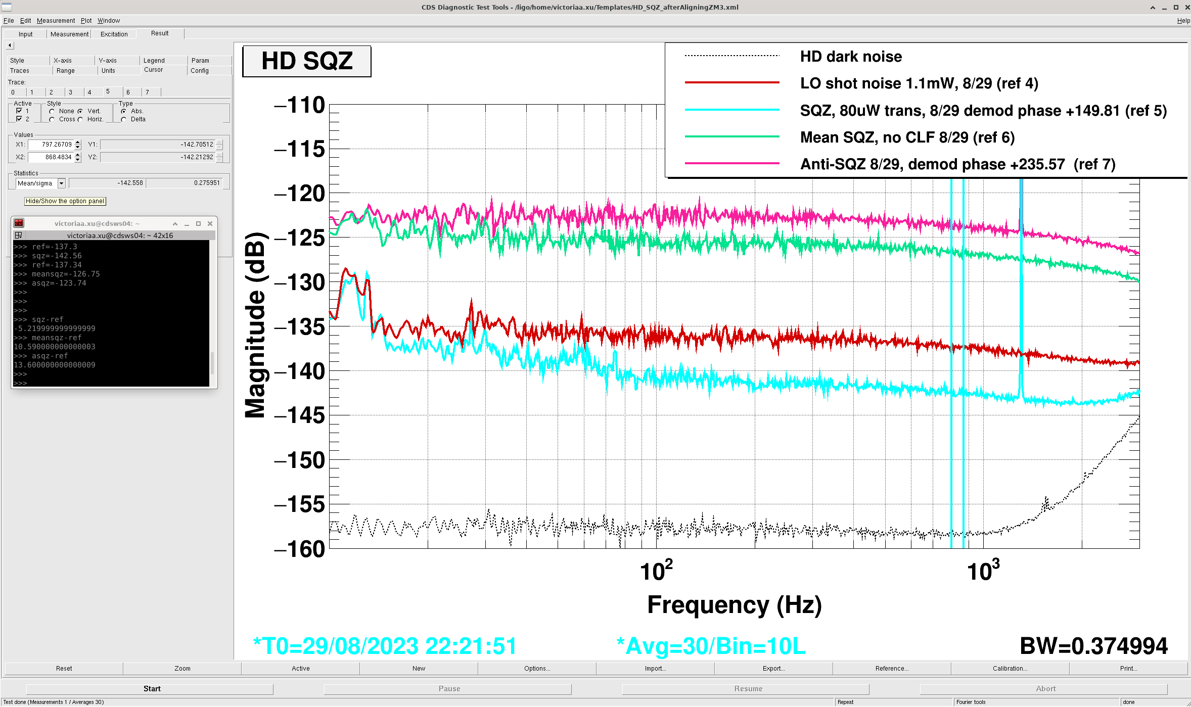
Including losses from phase noise of 20mrad, dark noise -21dB below shot noise, and a more accurate calibration of our measured non-linear gain to generated sqz level (from adf paper vs the aoki paper sheila referenced), the total efficiency could marginally be increased to 0.74. This suggests 26% loss based on sqz/asqz. This is also consistent with the 27% loss calculated separately from the mean sqz and generated sqz levels.
From the sqz wiki, we could budget 17% known homodyne losses. This includes 7% in-chamber loss to the homodyne (opo escape efficiency * ham7 optics losses * bdiverter loss), and 11% HD on-table losses (incl. 2% optics losses on SQZT7, and visibility losses of 1- 91.6% as Sheila said above (note this visibility was measured before changing alignments for the -5.2dB measurement; so there remains some uncertainty from visibility losses)).
In total, after including more loss effects (phase noise, dark noise), a more accurate generated sqz level, and updating the known losses -- of the 27% total HD losses observed, we can plausibly account for 17% known losses, lowering the unexplained homodyne losses to ~10-11% (this is still high).
From Sheila's alog LHO:72604 regarding the quantum efficiency of the homodyne photodiodes (99.6% QE for PDA, and 95% QE for PDB), if we accept this at face value (which could be plausible due to e.g. the angle of incidence on PD B), this would change the 1% budgeted HD PD QE loss to 5% loss.
This increases the amount of total budgeted/known homodyne losses to ~21%: 1 - [0.985(opo)*0.953 (ham7)*0.99 (bdiverter) * 0.98(on-table optics loss)*0.95(PD B QE)*0.916(hd visibility)].
From the 27% total HD losses observed, we can then likely account for about 21% known losses (~7% in-chamber, ~15% on-table), lowering unexplained homodyne losses to < 7%.

DRMI locked on its first try pretty quickly on the relock