Jim, Ryan C, TJ
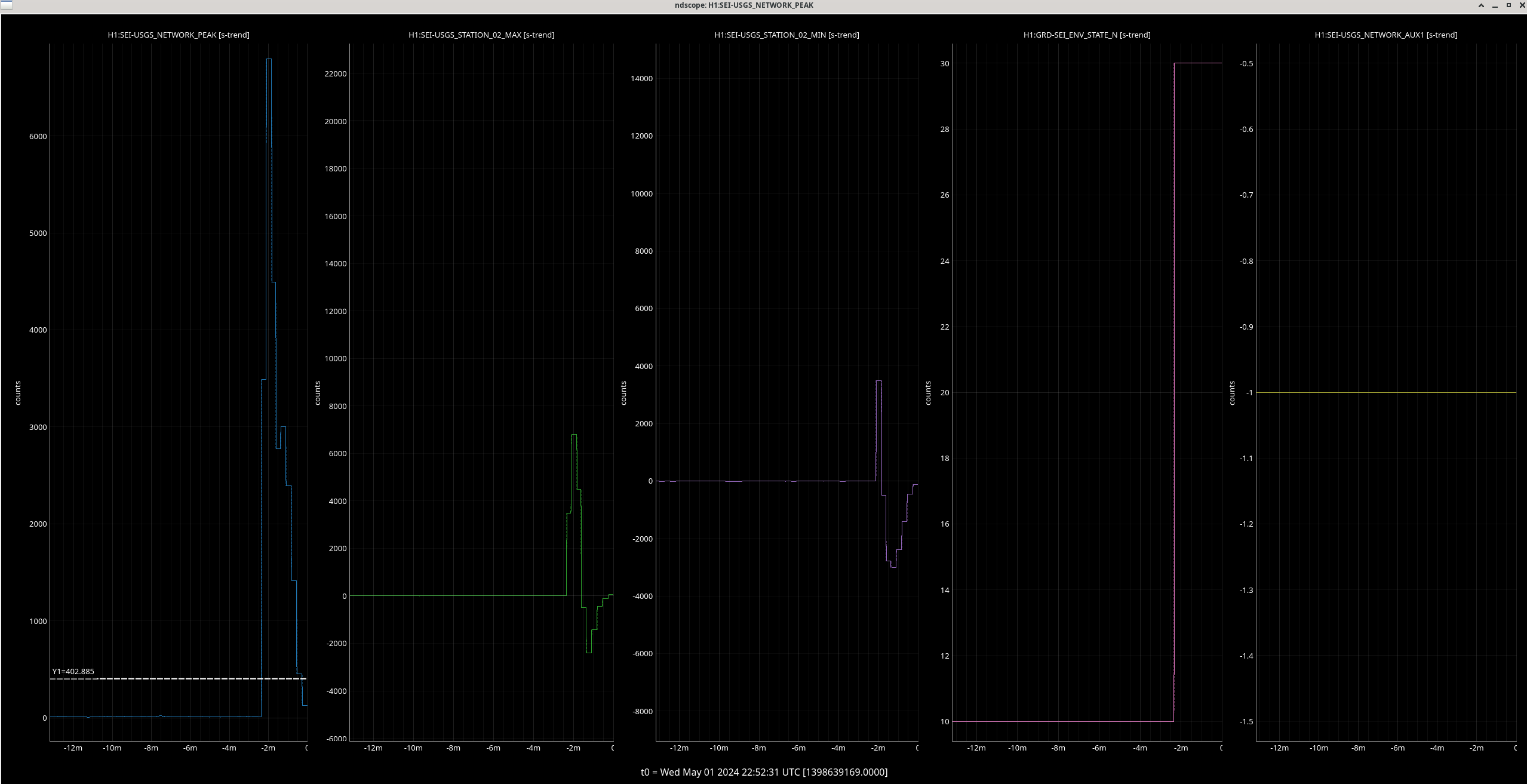
The picket fence station NEW had a large transient that put us into earthquake mode during observing. The code did not register this transient as a glich at first which caused the SEI_ENV mode transition. Looking to the picket fence code it looks like we might be able to tune the glitch settings a bit, but we would have to try out some values over a period of time. It might be worth checking with picket fence experts before we play with this code too much.
This isn't the first time we've seen this, but perhaps the first time we've aloged it. After the 10minute cool down period SEI_ENV returned back to a CALM mode.
The transient impulse happened a 2nd time shortly after from the same NEW station over by Spokane. It reached the glitch threshold about 5 minutes after the first impulse. Could there be work ongoing on this seismometer?
This lock loss had that the weird ETMX wiggle just before the lock loss that we've seen in past lock losses.
Back to Observing. Full auto relock but there was an SDF diff for the ITMY CP that was changed during commissioning in the Observe.snap, and came back after this last lock loss. I saved the new values in the safe.snap as well.
Back to Observing at 1926 UTC after a planned comissioning period. We were unable to get calibration measurements since the IFO lost lock just before planned commissioning and during commissioning.
Jennie W, Gabriele
I tested the offsets calculated by Gabriele's code that we used to analyse line dithers in the OMC ASC loops here.
We tested them during the commissioning period and put the following offsets into OMC-ASC_QPD_{A,B}_{PIT,YAW}_OFFSET. Since the offsets here were turned off by default I zerod them and then stepped them up slowly so we didn't saturate the OMC ASC loops.
See the attached ndscope showing kappa c improve after we finished putting these offsets in.
We lost lock about 15 minutes after I finished ramping these in due to unrelated issues.
Sheila suggested we put the all the offsets for the QPDs in one place. Since we already had offsets in the filter blocks: H1:ASC-OMC_{A,B}_{PIT,YAW}_OFFSET, I added the offsets for Gabriele's code in these filter banks instead.
I accepted these in safe.snap and OBSERVE.snap as well as the zero values for the OMC-ASC_QPD_{A,B}_{PIT,YAW}_OFFSETs.
offset = exisiting + offset from Gabriele's code
A_PIT = -0.25 - 0.12
A_YAW = 0.1 + 0.15
B_PIT = -0.05 - 0.12
B_YAW = 0.07 - 0.18
We will re-evaluate once we are thermalised.
I ran the A2L script descirbed here at the start of commissoning time this morning, and immediately after manually tuned P2L coefficents for the ETMs. I was able to improve the CHARD P to DARM coupling by about 25dB compared to the script's result. I tried tuning the ITM coefficents, but there wasn't much room to improve them.
I've updated the guardian values for ETMX, ETMY and ITMX (for a very small improvement on ITMX).
Compared to the script, my adjustments were fairly coarse. The script adjusted ETMX P2L from 3.1715 to 3.0875, while I then adjusted it to 3.35. For ETMY the script adjusted it from 4.682 to 4.7747, I adjusted it to 4.5. This resutls in the improvement shown in the attachment.
Editing to add: we relocked with these new P2L values, and the CHARD P to DARM coupling is still fairly low early in the lock (3rd attachment). The A2L coefficents aren't very sensitive to thermalization, which is good news.
J. Kissel, A. Effler Executive Summary: The calibration for all QTOP (D1001782) and TTOP (D1001242) coil driver's FASTIMON channels that are using the frequency-independent "current monitor" circuit of the broadband coil driver monitor circuit (D0902747) is QTOP = 0.0114 [mA/ct] and TTOP = 0.0153 [mA/ct], respectively with the "[mA]" being current across the coil, and "[ct]" being "straight off the ADC" counts. Derivation From the math outlined in the "Other Files" of the older, "broadband" coil driver monitor circuit, D070480 and stitching together how various voltage signals passed around from page to page of the drawings, one can compute the calibration of the FASTIMON channels for a given coil driver as FASTIMON ADC [ct] = voltage measured across two legs worth of output impedance in the coil driver board drawing * ( [differential legs' voltage to single-ended output voltage converter node in the monitor board drawing] * "single-ended voltage piped into only one leg of differential ADC" factor of two its DB25 output J1 in the interconnect drawing * general standards 16-bit differential ADC calibration) where calibration = (the stuff in parentheses) ADC [ct] [ "R1" [V_SE] ] 2 [V_DF] 2^16 [ct] ---------------- = [ 2 * Z_OUT [V_DF / A] * ----------- ] * -------- * ----------- Coil Current [A] [ "R2" [V_DF] ] 1 [V_SE] 40 [V_DF] where "R1" = R25, R35 = 10e3 [V/A], and "R2" = R24, R27, R29, R33 = 30e3 [V/A]. So, for the QUAD / Triple TOP coil driver (see circuit diagram D0902747 of chassis assemblies QTOP = D1001782 and TTOP = D1001242), that's, the output impedance of one leg is Z_OUT = (R5+R1) || (R90+R91) = (R5+R1) * (R90+R91) / (R5+R1 + R90+R91) Z_OUT^(QTOP) = (44 * 440) / (44 + 440) = 40.00 [V/A] Z_OUT^(TTOP) = (32 * 440) / (32 + 440) = 29.83 [V/A] which makes the calibration calibration_QTOP [ct/A] = 2 * 40.00 [V/A] * (10e3 / 30e3) * 2 * (2^16 / 40 [ct/V]) = 8.7381e+04 [ct/A] or 87.381 [ct/mA] or 0.0114 [mA/ct] calibration_TTOP [ct/A] = 2 * 29.83 [V/A] * (10e3 / 30e3) * 2 * (2^16 / 40 [ct/V]) = 6.5165e+04 [ct/A] or 65.165 [ct/mA] or 0.0153 [mA/ct] Q.E.D.
Gabeiele, Sheila, Camilla
Here's an analysis of those injections. In brief, the coil and mechanical responses are the same for ETMX and ETMY as expected. The differences are all due to filters in the L2 LOCK and DRIVEALIGN filter banks.
First plot shows a comparison of the L2 LOCK L EXC to CAL-DELTAL transfer functions for ETMX and ETMY: they look different.
In the second plot I plot the filter chain from the L2 LOCK EXC to the COILOUT. They are different, probably because ETMX is used for DARM control, and ETMY is in some legacy configuration (note that Camilla turned off the LPL2L3 filter). The third plot shows the ratio of the ETMY / ETMX transfer functions as measured, and what we expect from the different filters that are engaged. They match very well.
If we compensate the EXC to CAL-DELTAL transfer functions with the LOCK and DRIVEALIGN filter, and take the ratio, we get a transfer function pretty much at 1, as shown in the fourth plot.
Finally, I calibrated CAL-DELTAL_EXTERNAL in meters using Louis' file from /ligo/groups/cal/H1/reports/ and the fifth plot shows that the DARM / COIL transfer functions are pretty much the expected 1/f^2, with only a sign difference between X and Y.
In conclusion, there isn't anything wrong with ETMY PUM drive. More thinking is needed to understand why the LSC FF have a phase rotation much that is much larger at LHO than LLO, and how to better tackle that problem.
FAMIS Link: 25989
Only CPS which looks higher at high frequencies (see attached) would be:
Wed May 01 10:13:10 2024 INFO: Fill completed in 13min 6secs
Gerardo confirmed a good fill curbside.
https://ldas-jobs.ligo-wa.caltech.edu/~lockloss/index.cgi?event=1398618745
PRM and SR3 saturations before the lockloss, 2.5 hours into the lock so we still haven't been able to take a thermalized calibration measurement. The only invasive/potential LL causing work going on was some PEM tests by Robert.
TITLE: 05/01 Day Shift: 15:00-23:00 UTC (08:00-16:00 PST), all times posted in UTC
STATE of H1: Observing at 151Mpc
OUTGOING OPERATOR: Corey
CURRENT ENVIRONMENT:
SEI_ENV state: CALM
Wind: 4mph Gusts, 2mph 5min avg
Primary useism: 0.01 μm/s
Secondary useism: 0.13 μm/s
QUICK SUMMARY: Just got back into Observing after a lock loss, fully auto relock. Planned commissioning today from 9-12 PT
After yesterday's SQZ realigning 77530 we're nearly back to the squeezing levels we had before the output arm alignment shift 77427: 4.3dB above 1kHz, 3.3dB ~350Hz. Plot attached.
I made a small change to verbal_alarms tests in test.py to ignore the TEST node being in error as I plan on creating another state to test/learn some camera stuff and I don't want to annoy everyone in the CR with it going into error. Verbal alarms could use a restart to reflect these changes.
TITLE: 05/01 Eve Shift: 23:00-07:00 UTC (16:00-00:00 PST), all times posted in UTC
STATE of H1: Observing at 152Mpc
INCOMING OPERATOR: Corey
SHIFT SUMMARY: We are Observing and have been Locked for 1.5 hours. Overall quiet night with two almost fully automated relocks. Reminder that LVEA is still Laser Hazard
LOG:
LVEA is still in LASER HAZARD
22:49 Detector Locked for 52 mins and just got into Observing
22:50 Lockloss after 1m 14s Observing
22:56 Lockloss at LOCKING_ALS
23:08 Lockloss from TRANSITION_DRMI_TO_3F
23:49 NOMINAL_LOW_NOISE
23:52 Observing
03:35 Superevent S240501an
04:34 Lockloss
04:49 Lockloss from TURN_ON_BS_STAGE2
05:38 NOMINAL_LOW_NOISE
05:40 Observing
Start Time | System | Name | Location | Lazer_Haz | Task | Time End |
---|---|---|---|---|---|---|
23:07 | VAC | Jordan, Janos | EY | n | Turn off pump | 23:26 |
23:46 | Betsy, Brian OReilly | MY | n | Approved activity | 00:46 |
05:40 Observing
In 77236, Gabriele found the ETMY L2 DRIVEALIGN L2L filter bank has a "L2L3LP" engaged that might be making it harder for us to fit the LSC FF. Today we re-measured the LSC FF, not interatively, with both FF's off and the "L2L3LP" filter off.
Nothing changed but we hope to refit the feedforward and implement them later. When installed, we would need to turn "L2L3LP" filter off after the ISC_LOCK states have been transitioned back to ETMX (77240).
All code saved to /opt/rtcds/userapps/release/lsc/h1/scripts/feedforward/
Struggling to fit these.
I have a MICHFF (pasted below) that's a factor of 10 worse than usual (plot attached). We may need to try to put this in and measure iterativly next week.
zpk([-6.816742648521258+i*81.77990170298034;-6.816742648521258-i*81.77990170298034;-77.88634028587184+i*89.33349468557826;-77.88634028587184-i*89.33349468557826;-718.113182677264+i*694.9426298748548;-718.113182677264-i*694.9426298748548;900.2096672125509+i*1208.040185682559;900.2096672125509-i*1208.040185682559;44.6571105273674;-170.8240187509259;-448.0004789051675;-596.150964242976],[-7.116688087177324+i*81.29900739837851;-7.116688087177324-i*81.29900739837851;-310.9419719288208+i*548.6326527169308;-310.9419719288208-i*548.6326527169308;-27.13254150394529;-30.48270823801881;-135.6924431195733;-151.8787517615438;-191.3877206479833;-2313.589507955138;-2602.376933025248;-2783.911401801387],-3.94153891134724)
Somethings wrong with the SRCL data I exported (even after re-exporting), plot attached. Data prepared using NotItter_LSC_FF_PrepareData.ipynb
Gabriele found that the SRCL data was fine if (DELTA_L / SRCLFF_IN2) was exported but that the SRCLFF was even harder to fit than previously. We have taken TFs in 77542 to try to understand why.