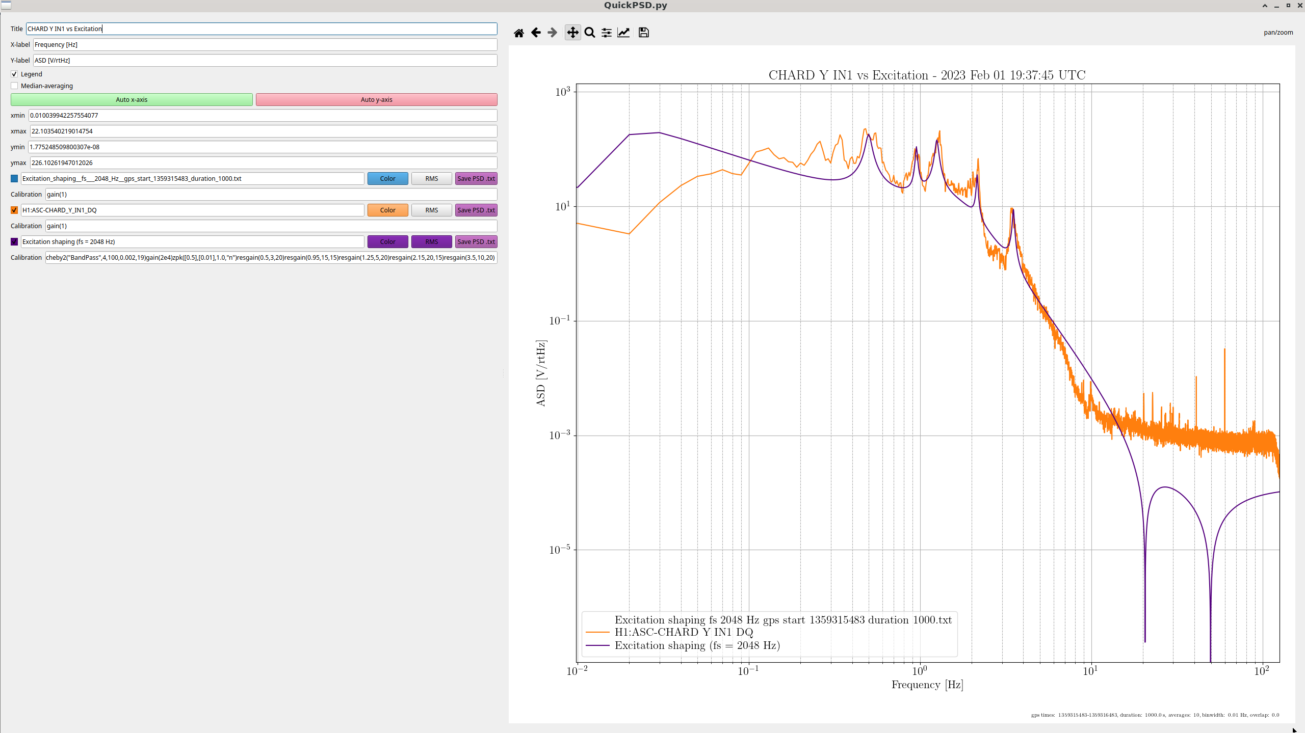
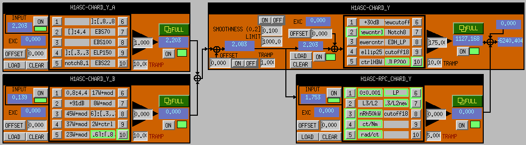
Long ago, Evan and Haocun measured DHARD P alog 27518. They determined that the way that DTT estimates OLG TFs is not really sufficient for regions where the excitation is not much much greater than the overall noise in the loop. At that time, they extracted the IN1/EXC and IN2/EXC manually from DTT, and estimated the OLG like (IN1/EXC)/(IN2/EXC) alog 27617. They also started using swept sine measurements to avoid bias and to achieve high coherence. However, swept sines at these frequencies are extremely slow, and the measurements are unwieldly (doesn't have the bandwidth you want, can cause locklosses by shaking hard at a sensitive frequency, forget to save the right A channels). Instead, I've drawn up a low-excitation long-term measurement infrastructure to estimate unbiased OLGs. The advantage of this code is it saves the EXC (and any other test points you want) directly to disk, so you can plot whatever binwidth and averages you want for the duration of the measurement. I stress tested this code by injecting into IMC-MCL_EXC for an hour, which saves three channels (IN1, IN2, and EXC) at fs = 16384 Hz. It saved a 458M .hdf5 file successfully. Not sure what the limitation on the data file size. Results For this lock on February 1, the CHARD Y gain had been doubled for stability reasons, to avoid 2.2 Hz ringups alog 67100. The digital filters had also recently changed alog 67101. From the 0.1 Hz bandwidth plot (PDF 2), we only have around -18 degrees of phase margin at 2.2 Hz. Increasing the gain by a factor of two gave us stability by pushing the UGF from 2.2 Hz to 2.0 Hz, where we have -27 degrees of phase. I would not have claimed that -18 degrees was enough to cause instability, but the interferometer could not lock without the CHARD Y gain increase. Additionally, it's possible to see why increasing it further would cause us instability at either 6.5 Hz or 1.4 Hz. Bounce and roll mode notches are at 9.7 Hz and 13.7 and 14.0 Hz, respectively. Future CHARD Y is totally dominating the ASC contribution to the DARM noise in the region of 10-25 Hz. Having measurements will help us reduce the loop gain in the 10-25 Hz region to avoid sensor noise reinjection will benefit to our DARM spectrum. Attached are the current CHARD Y regular and radiation-pressure compensation filters. It appears there is rapid phase loss in the 10-25 Hz region where the EDH_LP takes over. Evan notes that the regular and RPC filters add together with a different signs and the same magnitude, which kills our loop gain at 0.7 Hz (last two PDFs). Excitation smithing The main consideration for forging you excitation is 1) achieve a modest amount of coherence at the frequencies you care about, 2) runs for a long enough period of time that we can resolve the OLG with our modest coherence with enough averages, 3) doesn't cause a lockloss. I usually compare the excitation to the IN1_DQ error signal during full lock, and try to shape the excitation to mirror it, times the approximate loop gain to overcome the loop suppression. You can forge your excitation via foton using e.g.quick_psd H1:ASC-CHARD_Y_IN1_DQ -t1 1359315483 -d 1000 -b 0.01 --excitation --excitation_fs 2048then typing your foton string in the Calibration textbox for the Excitation channel, e.g.cheby2("BandPass",4,100,0.002,19)gain(2e4)zpk([0.5],[0.01],1.0,"n")resgain(0.5,3,20)resgain(0.95,15,15)resgain(1.25,5,20)resgain(2.15,20,15)resgain(3.5,10,20)It is critical to include the excitation channel sampling frequency, otherwise the injection strength will be misinterpreted byawgalog 67142. Code The code must be run in conda envlabutils, and exists in/ligo/home/craig.cahillane/Git/IFO/general/scriptsThe injection script ispython chard_yaw_injection_caller.pyThis script relies on the classautoBandlimitedNoiseSweep.pyI postprocessed this script usingipython -i postprocess_hdf5.py ~/Git/IFO/CHARD_Y/data/Injections/20230201/chard_yaw_injection_0p01_10p0_Hz_gps_start_1359339293.hdf5The injection script cannot be run by others as of now, only because it saves data directly into my own directory. I will work on putting something convenient in/ligo/gitcommon/so others can makes use of this.


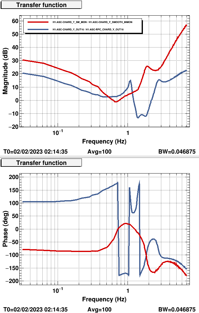
This is not a complete answer as Kevin is still working on getting an Optickle/Finesse simulation going, but I am attaching a transfer function of the overall feedback controller (i.e., the parallel sum of the CHARD Y and RPC CHARD Y filter banks) in red, and the ratio of the two controller portions in blue. Note that while the ~0.7 Hz zeros in the overall transfer function measurement appear to be in the right half plane, the nearby zeros in the controller are in the left half plane.
I have made a new location for these kinds of measurements:/ligo/gitcommon/noise_recorder/I am in the process of tuning slow, low coherence measurements for all ASC arm DOFs. Also, I developed some infrastructure to convert the true OLG into what I am calling "digital crossover" measurements. The digital crossover is when you inject into the CHARD_Y path, which is in parallel with the RPC_CHARD_Y path. The OLG is when you inject into the error point of the loop (or anywhere that's not in parallel). The good part about the digital crossover and OLG measurements is we know the digital filters perfectly and can convert between the two easily. The script is in/ligo/gitcommon/noise_recorder/code/asc_olg_to_crossover_tf_converter.pyTo use it, go into the code, give it an OLG and a GPS time, and run in 'labutils'. The code pulls the filters and reconstructs the digital crossover.
I forgot to add the plot of the "digital crossover" vs the actual OLG to the above comment:
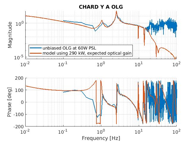
I have updated my model to model the OLG at the "A" point of the loop, and I have overlaid my model with Craig's measurement.
Model details:
- this model uses the L2 to L3 and L3 to L3 free suspension transfer functions of the test masses, as modeled by Brett Shapiro. I confirmed the modeled TF accuracy by measured the suspension transfer function myself.
- This model does not account for the M0 portion of the loop, as that will take effect at very low frequency (there is an integrator in the top mass locking filters)
- This model uses the old optical gain of the loop based on measurements I made a few weeks ago, 2.9e10 ct/rad. The loop has now changed slightly as we are sensing on the WFS 45
- This model applies the digital control and radiation pressure compensation in use when this measurement was made
- This model uses 290 kW of circulating power, which I determined by plotting several different arm powers and attempting to match Craig's measurement
There is discrepancy between the measurement and the model around 0.5 Hz. I don't have an explanation for that at the moment. I think we should remeasure and try to get better coherence and consider if that is a cross coupling feature, or some other unaccounted for phenomenon of the loop.
I have also made a .mat file of the freq, magnitude and phase from 0.01 Hz to 100 Hz