jeffrey.kissel@LIGO.ORG - posted 19:57, Wednesday 22 January 2014 - last comment - 17:30, Friday 07 March 2014(9453)
H1 SUS PR2 Coil Balancing Complete
J. Kissel [with lots of help from K. Kawabe, K. Arai, S. Ballmer, and K. Izumi]

I've balanced the coils on the M2 and M3 stages of the H1 SUS PR2 using Keita's Technique (see LHO aLOG 9079 -- which, now that I understand -- I'll make sure to supplement this aLOG with kLOG comments about it). However, before I exercise my didactic tactics, the answer is:

H1 SUS PR2
Channel     Balanced COILOUTF Gain
M2 UL            -0.994
M2 LL            +1.039
M2 LR            +0.962
M2 UR            -1.005

M3 UL            -0.962
M3 LL            +1.043
M3 UR            +0.954
M3 LR            -1.034

I attach the results of the balancing as measured by the M3 OSEM sensors behind the optic, one for each stage of drive balancing. The left two panels of each attachment (Amplitude Spectral Density and Coherence) show the performance AFTER the balancing, and the right two panels show the performance BEFORE the balancing, where coefficients were just set to +/- 1.0. This balancing has reduced the coupling (at 4.1 [Hz]) as follows (using the M3 OSEMs as the figure of merit, which -- details in notes below -- are imperfect):

   DOF                  Reduction Factor @ 4.1 [Hz]
M2 Pringle to M3 P           > 178               (peak is in the noise, and only ~60% coherent)
M2 Pringle to M3 Y             35

M3 Pringle to M3 P             1.4
M3 Pringle to M3 Y             4.5

The next step is to take a full suite of M2 and M3 L/P/Y to P/Y, "off-diagonal" transfer functions with the newly balanced coils, as has been done with *unbalanced* coils on H1SUSBS and H1SUSPRM.

I have captured a new safe.snap that includes these new gains and committed it to the userapps repo.

Expert Notes for next time:
- Three different suspensions, three different people, and three different options for sensors resulted in three different details of how the the process was done, but the process is the same, in principle. With PR2, the only option for sensor demodulation were the sensor side of the OSEMs at the bottom stage. Because these sensors are not perfectly balanced, the precision to which I could improve the balancing was limited -- much more so on the M3 stage than the M2 Stage. I'll explain the details below.

- These coefficients were established to higher precision, but were rounded off to the nearest 1000th's digit because they will be easier to track, entirely visible on the MEDM screen, and the higher precision had little-to-no affect on the goodness of balancing.

- The templates for measuring the performance can be found here:
/ligo/svncommon/SusSVN/sus/trunk/HSTS/H1/PR2/Common/Data/
2014-01-22_H1SUSPR2_M2_CoilBalancing.xml
2014-01-22_H1SUSPR2_M3_CoilBalancing.xml

- The script used to perturb the coil balancing based on the results of the LOCKIN tool (authored by Kiwamu, made slightly more generic by me),
/ligo/svncommon/SusSVN/sus/trunk/Common/PythonTools/perturbcoilbalance_fourosem.py
Note, the script isn't fancy enough to perturb the gains automatically to minimize the demodulated error signal, that's done by-eye using a few by-hand iterations of this script and watching the results in StripTool.

- I've used a compromise of filters than Kiwamu and Keita inside the LOCKIN, which I'll motivate in the comments below. For the oscillator clock frequency band pass (in the DEMOD_SIG banks) I used
butter("BandPass",2,3.5,4.5)
and called it "BP4.1Hz," and for the I and Q low-pass filter, I used
cheby1("LowPass",2,3,0.05)
and called it "CLP50mHz."
These seem to have worked out well (for my patience level), and can be copied as long as the clock frequency remains the same (which should be assessed anew for every SUS type.)
Non-image files attached to this report

Comments related to this report
On which sensor to use for your demodulated signal

In order to best balance the coils one wants a sensor that captures what affects the cavity alignment the best. This is typically some sensor measuring the optic motion. However, each suspension type tried thus far has had different options.

- H1 SUS BS, a BSFM (Balanced by Keita) has only an optical lever measuring the optic. So this was the obvious choice, and as such, the LOCKIN part is directly hooked up to it. Good.

- H1 SUS PRM, an HSTS (Balanced by Kiwamu) does not have an optical lever. However, it *does* have OSEMs on the bottom stage. These are hooked up to the LOCKIN as the optical levers are on the BS. HOWEVER, the OSEM sensors, which are in the same location as the actuators, so if the basis transformation from UL LL UR LR to Optic P and Y are imperfect, then that limits the precision to which you can balance the coils. As such, Kiwamu constructed a make-shift optical lever using the REFL WFS at DC, which act like a QPD and the light source is the transmitted light from the IMC: because PRM is a 3% transmission mirror, it reflects tons of light into HAM1 when the PRC is not locked. A rather expensive light source, but GENIUS! As Kiwamu mentioned however, this work-around wasn't hooked up to the demodulator, so he just used the ASD as his figure merit.

- H1 SUS PR2, which has also has no optical lever, and because of the transmissions of the mirrors in the PRC, one can't get enough light on any nearby WFS or QPD to pull the same Izumi trickery, so we're stuck with the imperfect OSEMs.

Once we get cavities under stable lock, we can revisit these optics which have no lever (i.e. all HSTS), because then we'll have the full ASC system with light everywhere at our disposal. But in summary, PRM is the only mirror lucky enough to do this trickery. Thankfully, as shown above, the M3 OSEMs can get some of improvement by themselves (as reported by themselves; of course we should check the improvement with global control loops and interferometers).

*nudge*nudge* Integration Issue 461 *nudge*nudge*
On the signal processing filters and OSC frequency for the LKIN part

In the lock-in amplifier process, we want the average amplitude of the product of the oscillator and the response signal (filtered at that same frequency). This average value provides a metric of the linear coupling to the drive at the oscillator frequency which one can minimize, with the benefit of directionality. In order to isolate this DC, average value of the product from the bilinear term, we low-pass the output of the demodulator. The design metrics of this low-pass are a function of the oscillator frequency chosen and, in our case, the patience of the user:
(1) One wants a significant amount of isolation at twice the oscillation frequency, such that the 2f "noise" does not interfere with the average DC value, but
(2) The response time of the low-pass filter defines how many cycles which the average includes, and therefore the response time of your metric to the knobs you have to change it.
As such, one wants a high oscillation frequency with respect to the corner frequency of the low pass.

However, we have further design constraints:
(3) Given that the SUS actuators are weak and the particular, off-diagonal, mechanical response to our excitation is so small at high-frequency, signal-to-noise and/or coherence limit how high we can push of oscillator frequency to roughly 5 [Hz].
(4) Ideally, the SUS response to pringle excitation should be frequency-independent, if we've done a proper job of digitally compensating for the analog frequency response of the actuation chain. But, if one chooses a low oscillator frequency -- say 0.1 [Hz] -- then the averaging low-pass filter will have to be much lower, and the response time becomes unbearably slow -- hundreds of seconds.
(5) In the middle, between ~0.5 [Hz] and ~5 [Hz] is a forest of SUS resonances, which, if excited, might result in all sorts of unexpected coupling to degrees of freedom not of interest, saturations of sensors, etc.

This leaves a tiny region between the given suspensions' resonant forest and where coherence drops off to stick the oscillation frequency. Keita chose 2.9 [Hz] on H1 SUS BS, and Kiwamu chose 4.1 [Hz] on H1 SUS PRM after considering these constraints, and because H1 SUS PR2 was the same SUS type as H1 SUS PRM, I stuck with Kiwamu's frequency of 4.1 [Hz].

Once the oscillation frequency is chosen, and the response signal, band-pass filter can be designed. Here, you want to isolate the response signal at the given oscillator frequency, but you need to be mindful that the impulse response of the band-pass filter is shorter than of the demodulated signal's low-pass filter. Here's how we each designed our filters:

Keita's approach (for H1 SUS BS): Lots of isolation on both the response signal band-pass and demodulated low-pass, and forgo patience. With a sharp cut-off, elliptic, band-pass the response time was greater than 5 seconds. The a sharp cut-off, elliptic low-pass, the averaging time was more than 100 sec.

Kiwamu's approach (for H1 SUS PRM): Less isolation for the less patient. Reduce the sharpness of the cutoff of both the band-pass to second order Butterworth filters, and increase the corner frequency of the low=pass to 300 mHz to reduce the averaging time to ~20 seconds. Note that he had started with an oscillator frequency of 10 [Hz] (hence the center frequency of his band-pass), but found the could not get enough coherence, reduced the oscillator frequency, and got enough response signal at 4.1 [Hz] to leak through to make a viable demodulated signal, so he didn't bother to change the design of the band-pass.

Since I just learned all of this today, and had Kiwamu, Stefan, and Keita telling me different metrics for their design, I chose what made sense to me (for H1 SUS PR2): Compromise. Move the center frequency of Kiwamu's band-pass to the oscillator frequency, but leave the shallow isolation in order to preserve the short impulse response time. Take the happy medium regarding patience and move the corner frequency of the demodulated low-pass to 50 [mHz]. This gave me plenty of SNR, lots of averages, and a impulse response time of the demodulated signal metric similar to Kiwamu's; about 10-20 seconds.

I attach bode plots and impulse response times for each of the three filters, color coded as above, with H1 SUS BS, H1 SUS PRM, and H1 SUS PR2.
Non-image files attached to this comment
Measurement Technique Expanded

Though Keita did a fairly good job explaining the principles of the technique in LHO aLOG 9079, I expand on his instructions with a little more detail below for the non-Jedi, and such that we might one day automate the process.

(A) Install the signal band-pass and demodulated I & Q filters; the same BPs in both oscillators' SIG bank, and the same LPs in both oscillators' I and Q banks.
SIG band pass: BP4.1Hz = butter("BandPass",2,3.5,4.5)
DEMOD I & Q low-pass: CLP50mHz = cheby1("LowPass",2,3,0.05)

(B) Turn on both the Pitch and Yaw Oscillators.
As Keita mentions,
   (i) Only the amplitude of the oscillator you send out the coils matters, but the other must at least be *on* in order for the demodulation to happen,
   (ii) For each oscillator, the amplitude of the sin and cos don't matter, as long as they're the same,
   (iii) You want to demodulate both oscillators at the same frequency, so the oscillator frequency should be the same for both.
For sanity's sake, I just made both oscillators have exactly the same parameters
OSC     Frequency [Hz]     Amplitude [ct]     Sin [ct]      Cos [ct]
 P         4.1              200000 (2e6)       1000           1000
 Y         4.1              200000 (2e6)       1000           1000

(C) Turn on the EXC_SW for the stage you wish to balance, and filling out the associated stage's LKIN2OSEM matrix such that only one oscillator drives in a pringle configuration (I, like Keita, chose to use the Pitch oscillator),
     P   Y
UL  +1   0
LL  -1   0
UR  -1   0
LR  +1   0

(D) Open up two StripTool charts, one for each oscillator. Put the output of the I & Q demodulator banks for each oscillator on each tool, (e.g. H1:SUS-PR2_LKIN_Y_DEMOD_I_OUTPUT and H1:SUS-PR2_LKIN_Y_DEMOD_Q_OUTPUT). Be sure to set the y-scale for each channel to be consistent (+/- 10 [ct] worked for me, and then I zoomed in and out as necessary).

(E) Tune drive amplitude. I was initially scared of the large drive amplitudes Kiwamu had chosen, so I crept up on 200000. However, this meant when I started out with 10000 [ct], I got very little response when I began to tune the oscillator phase. So, crank up the drive to where you get lots of response to changing the oscillator phase, while making sure not to saturate the DAC.

(F) Tune the oscillator phase
    (i) Again, drive hard enough that the separation between the I & Q phase is much larger than the noise (noise = wiggles around the DC value)
    (ii) Spin through the DEMOD Phase until you get the Q phase near zero
    (iii) Use Kiwamu's script mentioned in the main entry, perturbcoilbalance_fourosem.py, to put a *large* coil imbalance into the COILOUTF bank. This should cause a step in both the I & Q signals. The arctangent of the ratio between the the step sizes gives you the remaining distance you are away from the ideal phase:
             dPhi = 180/pi * atan( (Q_DC^{before} - Q_DC^{after}) / (I_DC^{before} - I_DC^{after}) )
The sign with which you add this to the current oscillator phase is unclear, so try both. A well-tuned oscillator phase means that abs(Q) is close to zero, and it doesn't respond [it's DC value doesn't change] to coil imbalance changes. Note, any offset the Q phase has from zero is noise that you can't tune away with the COILOUTF gain knobs. As mentioned in the above comments, this can be a result of, for example, imperfect sensors. As long as Q doesn't respond to coil unbalancing, then it's OK -- it's just one of limits on how well you can balance the coils. You'll need to tune the phase of each oscillator independently.

(G) Set COILOUTF gains back to +/-1. Open up a DTT session (like the templates shown in the main entry), and set up a rolling averaged transfer function between the oscillator and the response sensor input. For PR2, that's H1:SUS-PR2_LKIN_P_LO (as the A channel) and H1:SUS-PR2_M3_WIT_P_DQ, H1:SUS-PR2_M3_WIT_Y_DQ. Take a reference measurement of 10-15 averages to show how badly the pringle excitation causes pitch and yaw in your response sensor.
Remember: (as Keita says) A Pitch imbalance shows up in the Yaw oscillator's I phase, and a Yaw imbalance shows up in the the Pitch oscillator's I phase.

(H) Begin tweaking the COILOUTF bank gains (using perturbcoilbalance_fourosem.py) until the abs(I) phase goes to zero. You should stop when the noise is larger than the distance between the DC value ad zero. For the M2 and M3 stages of PR2, a perturbation of +/- 0.0005 was the precision I was able to achieve. If your oscillator phase is tuned correctly, a PIT imbalance should not affect the Pitch I phase, and Yaw imbalance should not affect the Yaw I phase. Therefore, you can do these degrees of freedom in succession, and not have to worry about going back and fourth.

(I) Because perturbcoilbalance_fourosem.py was quickly written, the perturbation increments are not exactly what you request. So by then end of the tuning process for both DOFs you'll have overly precise gains (check by caget-ing the gains in a terminal). Round off these gains to the nearest 1000th for reasons mentioned in the main entry.

(J) Making sure to have captured the "before" measurement as a reference, take a new DTT spectra to prove how well you've done!
Demod Phases and Resulting I & Q Values

After balancing the coils, I took a 300 second tds average of each I and Q channel just so I'd have a quantifiable number of "how good" I tuned the balancing. Unfortunately, there's no command line standard deviation tool, so I don't have a number for how much noise was on each channel. It was roughly +/- 0.5 [ct].
PR2 M2
     Demod Phase [deg]         Balanced Value
P       165              I         -0.017
                         Q         -0.088
Y       90               I          0.14
                         Q          0.52

PR2 M3
     Demod Phase [deg]         Balanced Value
P       160              I         0.15
                         Q         1.91
Y       87               I         0.11
                         Q         3.14

As one can see, the residual offset in the Q phase was much larger on the M3 stage than on M2. Unclear why this is, but this most probably is the reason why the results for M3 are not nearly as good as those for M2. It would be nice to have an independent sensor to verify the results, but we'll have to wait for resonant cavities and the full ASC system.
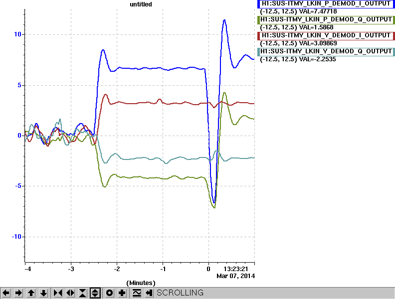
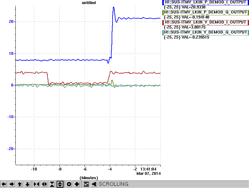
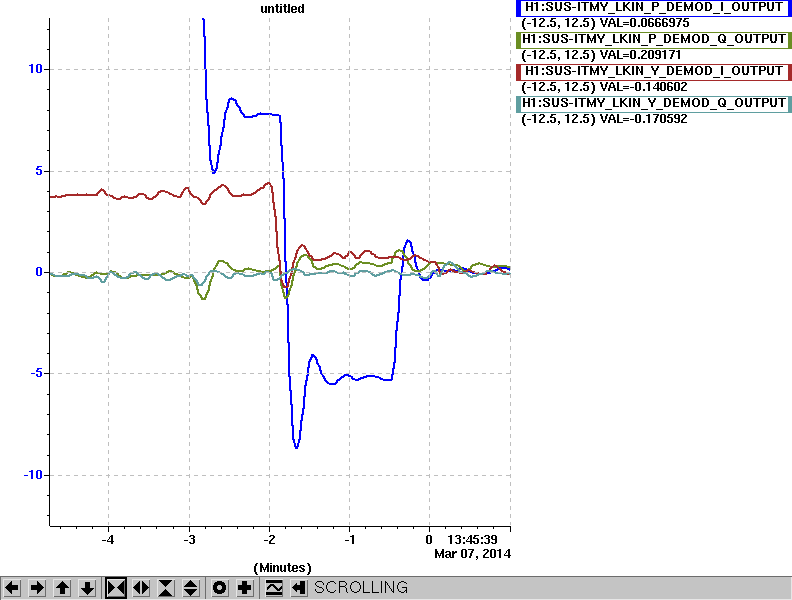
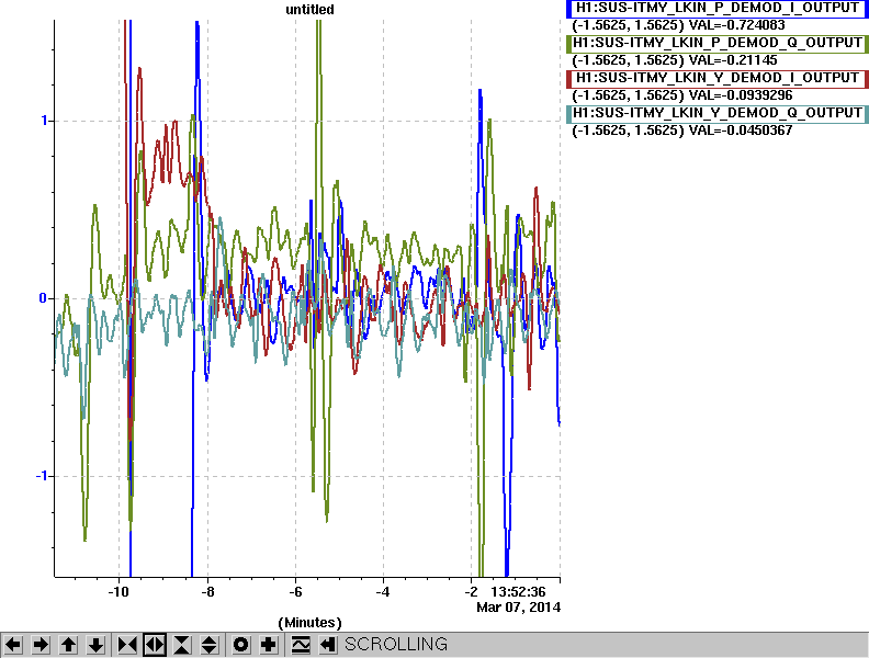
Here're a few screenshots of the StripTool session during the tuning process. They're attached in chronological order, showing
(1) Aligning the optical lever, to show the difference between junk signal and plenty of signal, then after hand-tuning the demod phase to get the Q phases close to zero
(2) Before and after the big perturnations to gather the tweak needed in the demod phase, as determined by math
(3) The process of balancing the coils once the demod phase is perfect, bringing the I phases to zero as well, with little perturbations to the balance
(4) What balanced coils look like (strikingly similar to junk signal, but just signal doesn't respond to perturbations), also what it looks like to have saturations (sudden increase in I and Q phase signal amplitude).

You should be able to get a good amount of SNR exciting with an oscillator amplitude between 115000 and 125000, depending on the strength of your driver, and how much you've imbalanced the coils.
Images attached to this comment