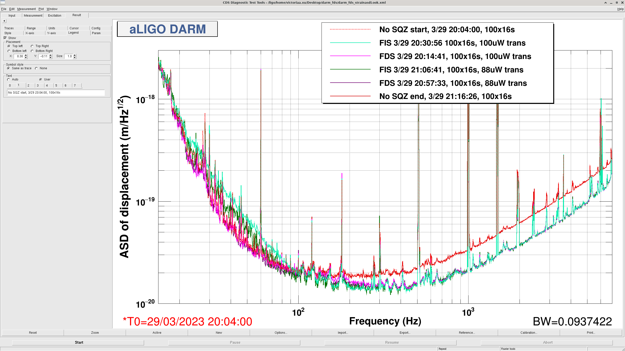
I have made an updated noise budget using the Cal Delta L trace. Currently, there is no channel with online cleaning implemented, although that is a work in progress. We can use this noise budget and the traces to estimate how much more sensitivity we might gain when the cleaning is applied. Also, The current cal delta L trace is calibrated, so no calibration"fudge" was required to make this budget.
I reran all injections for the ASC, LSC, Laser and Input Jitter budget. Kevin and Vicky have been working on the proper calculation of the quantum vacuum trace, and the quantum subbudget. This budget uses the "semiclassical" estimation, which may not be fully accurate. However, for these purposes, I think it is sufficient.
I purposefully removed the PUM DAC noise from this budget, as I am worried that the calculation may be inaccurate. Craig recently switched coil driver states to get a projection of our current PUM DAC noise (alog 68489). Craig states that this projection is 20 times lower than what the noisemons are telling us. I think it is best to leave out the DAC noise until we can determine what is correct.
Subbudgets:
Overall, compared to the 60W noise budget (alog 68382), the noise traces are about the same. That budget showed us limited by MICH (if you ignore PUM DAC), and limited by jitter. The high frequency laser noise has improved. The ASC budget has improved. We are still limited by unknown noise in the mid range.
I will follow up with a comparison of the NB traces at 60W and 76W. I think if we can subtract the jitter noise, especially in the bucket, the comparison will show us improved sensitivity in the region when operating at higher power.
I ran a bruco on the quiet time used for the noise budget. https://ldas-jobs.ligo.caltech.edu/~elenna.capote/brucos/CAL_NB4_19/
I have not looked at all the results completely but I will point out the ones that I noticed:
The attachments compare the strain noise and comoving horizon volume for a time corresponding to this recent noise budget and for a time last month corresponding to an earlier noise budget. The sensitive volume is about the same for systems below 50 solar masses total — corresponding to something like a 70% increase compared to O3. But the IMBH sensitivity is vastly different, with the previous month's performance being much better than this month's.
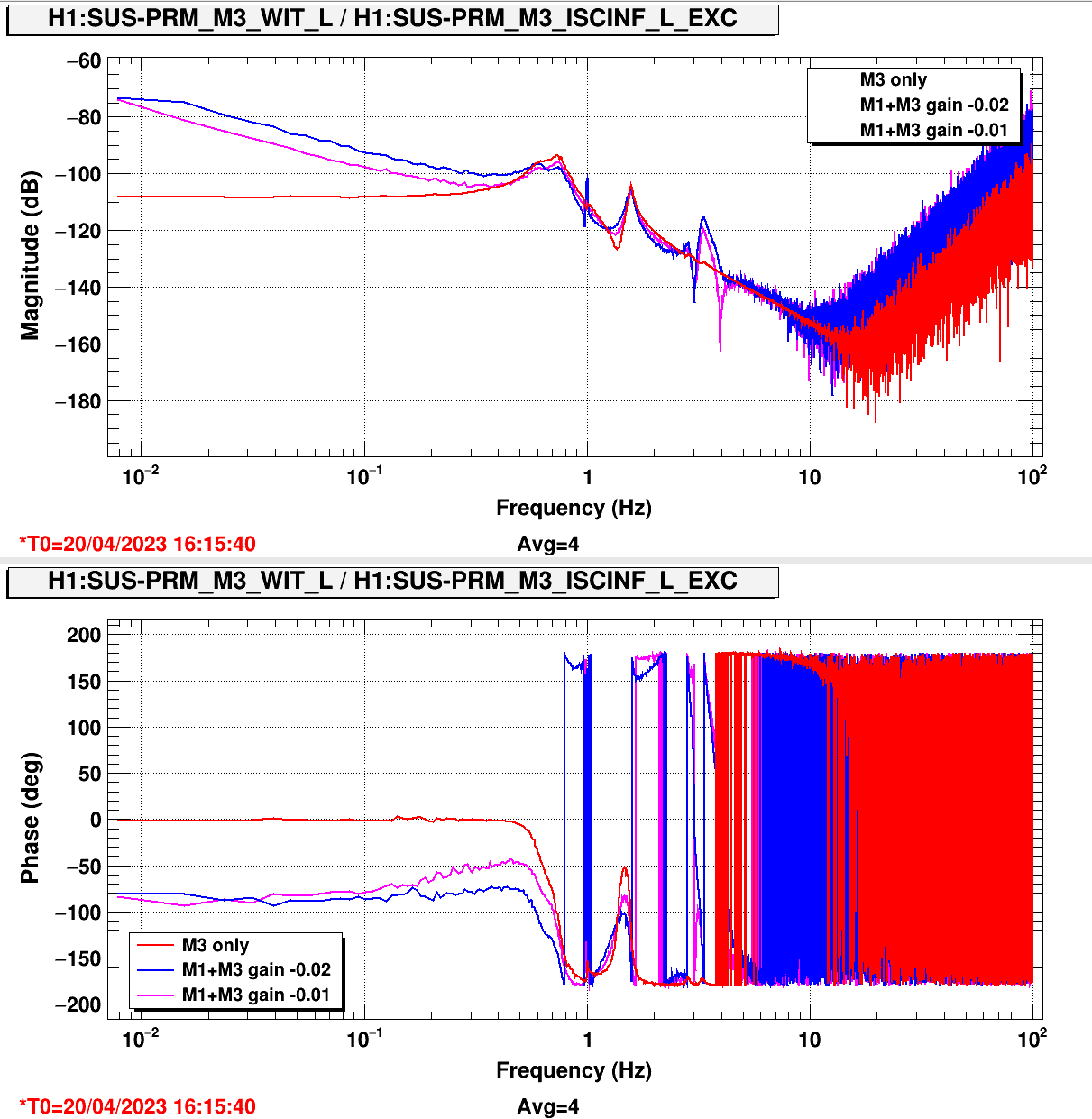
No suprise that the M1 offloading of PRM length actuation caused a large 3.4 Hz peak.
With the IFO down, I measured the PRM length lock actuation in three configurations:
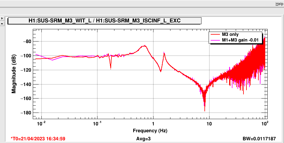
Look at the attached plot: when offloading to M1, we create a huge peak at 3.3 Hz in the PRM actuation, and the trasnsfer function is very different from what we get with M3 only. Reducing the gain by a factor of two improves the situation just a little bit.
So PRM offloading need some work.
I took measurements of the M1 and M3 actuations, we can use them to design a new offload.
I wonder if the other HSTS are in the same situation: SRM has a very similar offload filters (with gain of -0.01)
Tagging ISC and CSWG. For the record, Shiela recently designed offloading for the filter cavity control -- see LHO:66092. Maybe this is a useful starting point. The first aLOG I found on PRM offload design is from 2015, LHO:21084; this might be the last time it was reviewed. She's conveyed to be several times that she's been confused / disappointed in the HSTS matlab model's ability to support the efforts of design -- it might be worth a look there too. You may find a tagged version of the HSTS model in hstsmodelproduction-rev4067_ssmake3MBf-rev1891_hstsopt_metal-rev2039_released-2013-01-31.mat. Information to calibrate that modeled transfer function collection from fundamental units (e.g. m/N, or rad/N.m) can be found in both the controls design description for the HXTS, T1000061, and summarized in the controls design summary table, G1100968. A reminder that H1's PRM is driven still by 18-bit DACs, so the calibration is 20 / 2^18 [V/ct]. I have not had the time to digest Sheila's scripts from LHO:66092 or earlier to understand where her mysteries and source of complaints lie. I've at least been able to verify the top mass sensor and actuator calibration to within a factor of 1.5x through my damping loop designs, e.g. LHO:65310, designed by ^/trunk/HSTS/Common/FilterDesign/Scripts/design_damping_HSTS_20221110_H1SRM_ActualHSTSLeverArms.m.
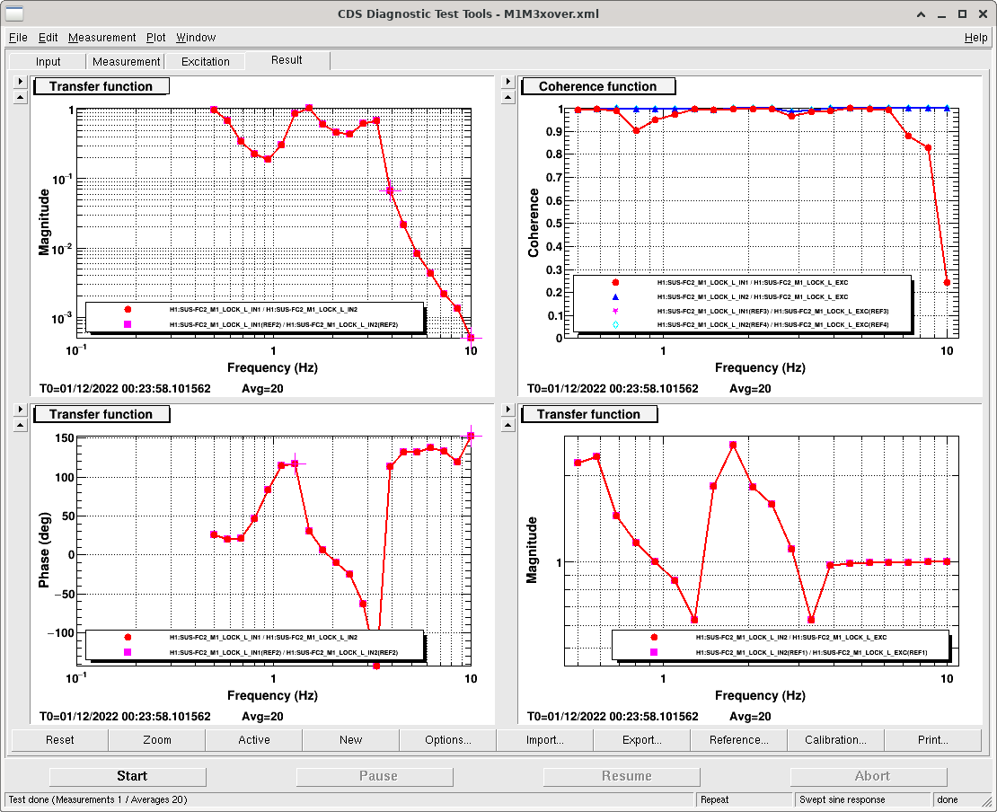
In particular, for FC2 SUS control, Sheila had to add in a 1.3Hz phase wiggle (FC2, M1 stage, FM5 "wig1.3Hz") to make our M1/M3 crossover stable. But, from our FC2 M1/M3 crossover measurement, notice that beyond 1.3Hz, FC2 indeed seems to have a second instability at about 3.4 Hz, which has ~2x gain clearance and no phase margin from becoming unstable.
I took a quick (just 3 averages) measurement on SRM (as requested by Gabriele) and I didn't see any 3,4Hz peak with M3+M1 offloading and nominal gain of -0.01. At the next target of opportunity I will check other HSTS.
TITLE: 04/20 Day Shift: 15:00-23:00 UTC (08:00-16:00 PST), all times posted in UTC
STATE of H1: Commissioning
CURRENT ENVIRONMENT:
SEI_ENV state: CALM
Wind: 9mph Gusts, 5mph 5min avg
Primary useism: 0.02 μm/s
Secondary useism: 0.17 μm/s
QUICK SUMMARY: H1 just unlocked after 7 hours as I walked into the Control Room, will start invesitgating the cause. Holding in DOWN to run PRM measurements. BRSY is ON.
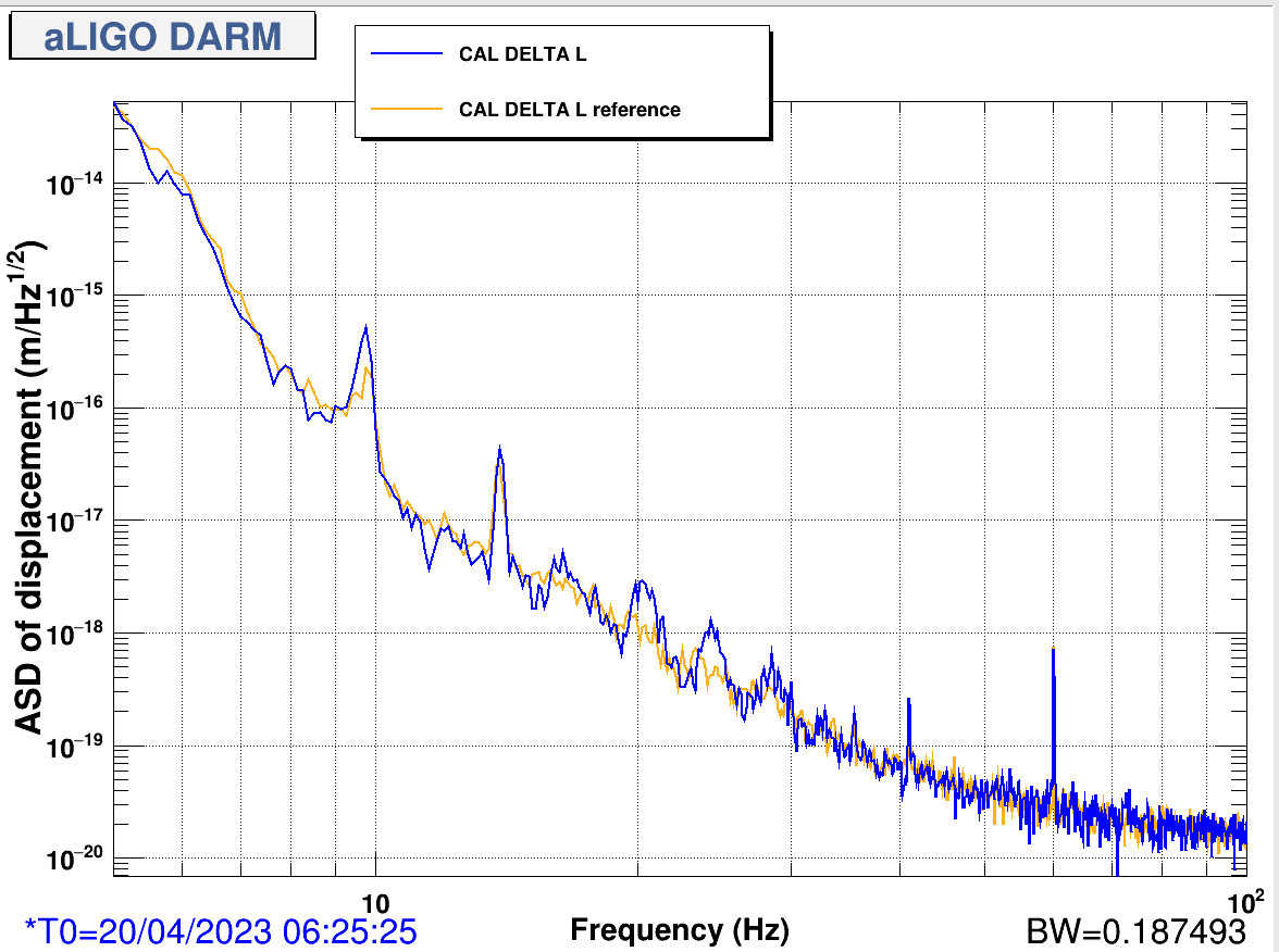
This is a feature that has been noted in other alogs, such as 68679, but there is a recurring transient noise source from approximately 20-40 Hz. It appears as a broad peak or bumpy structure, usually starting at 20 Hz. The peaks appear to be spaced about 4 Hz apart. This structure has been visible in the past, but it appeared very frequently in DARM tonight. The broadness and prominence of the peaks vary; sometimes they are much sharper, and have more harmonics. I have been loosely keeping a list of times when it appears, and I attempted to run a bruco on one of those times but it didn't indicate any additional coherence from 20-40 Hz than normal.
I'm tagging DetChar and PEM to hopefully follow up more on this!
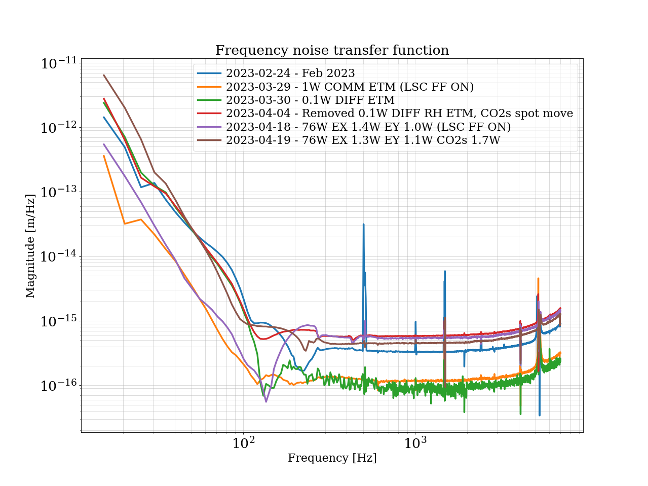
Tonight after IFO thermalization, I remeasured the frequency noise and the contrast defect. Earlier in the day we changed the ring heaters to be set to 1.3 W on EX and 1.1 W on EY. The contrast defect is now down to 1.7 mW, comprable to a measurement made recently by Dan. Our frequency noise has also reduced at high frequency.
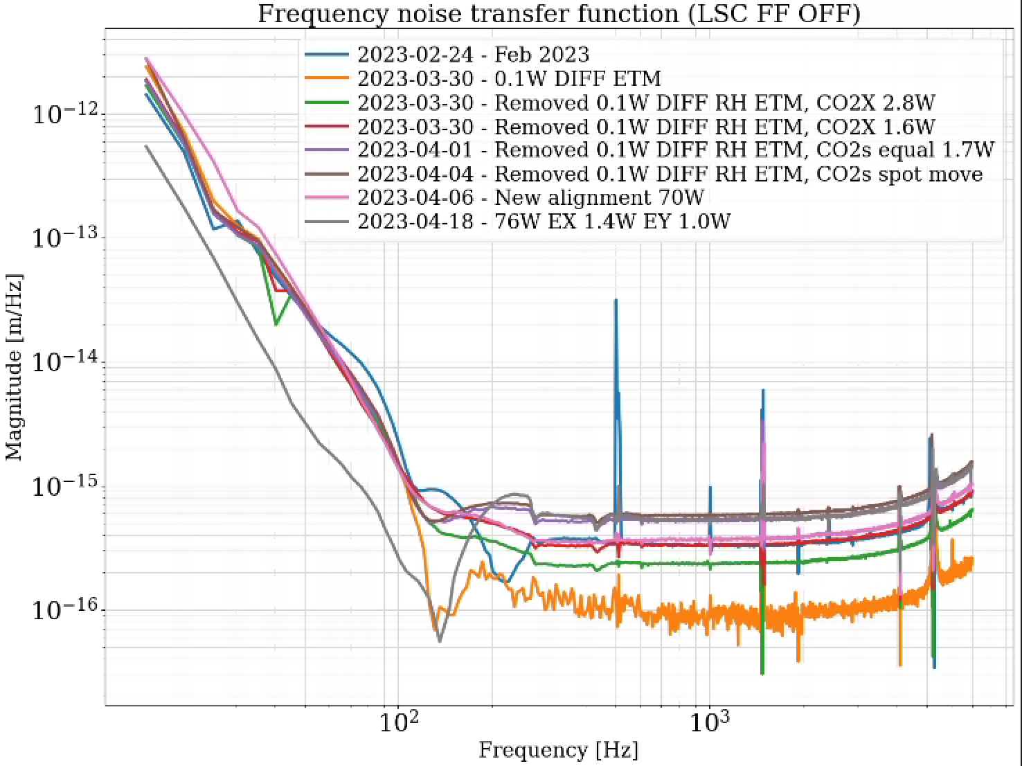
I have added a new frequency noise trace to the plot I put in a comment in alog 68842. See new plot below. I was sure to turn on LSC FF this time during the measurement. Comparing the brown and purple trace, our frequency noise is reduced from the ring heater change.
We could either step ETMY up again to 1.2 W and see if we gain even more, or we can call this setting good enough and stay here. The CO2s have some effect on the frequency noise, so we may be able to tune more improvement there.
LHO:65000 Craig calculates the homodyne angle, based on measured contast defect and total dcpd power:
contrast_defect = 1.7 mW
total_dcpd_light = 20 mW
darm_offset_power = total_dcpd_light - contrast_defect = 18.3 mW
homodyne_angle = arctan2(sqrt(contrast_defect), sqrt(darm_offset_power))
homodyne_angle = 17 deg
Craig also notes this 17 deg would be an upper limit on the homodyne angle.
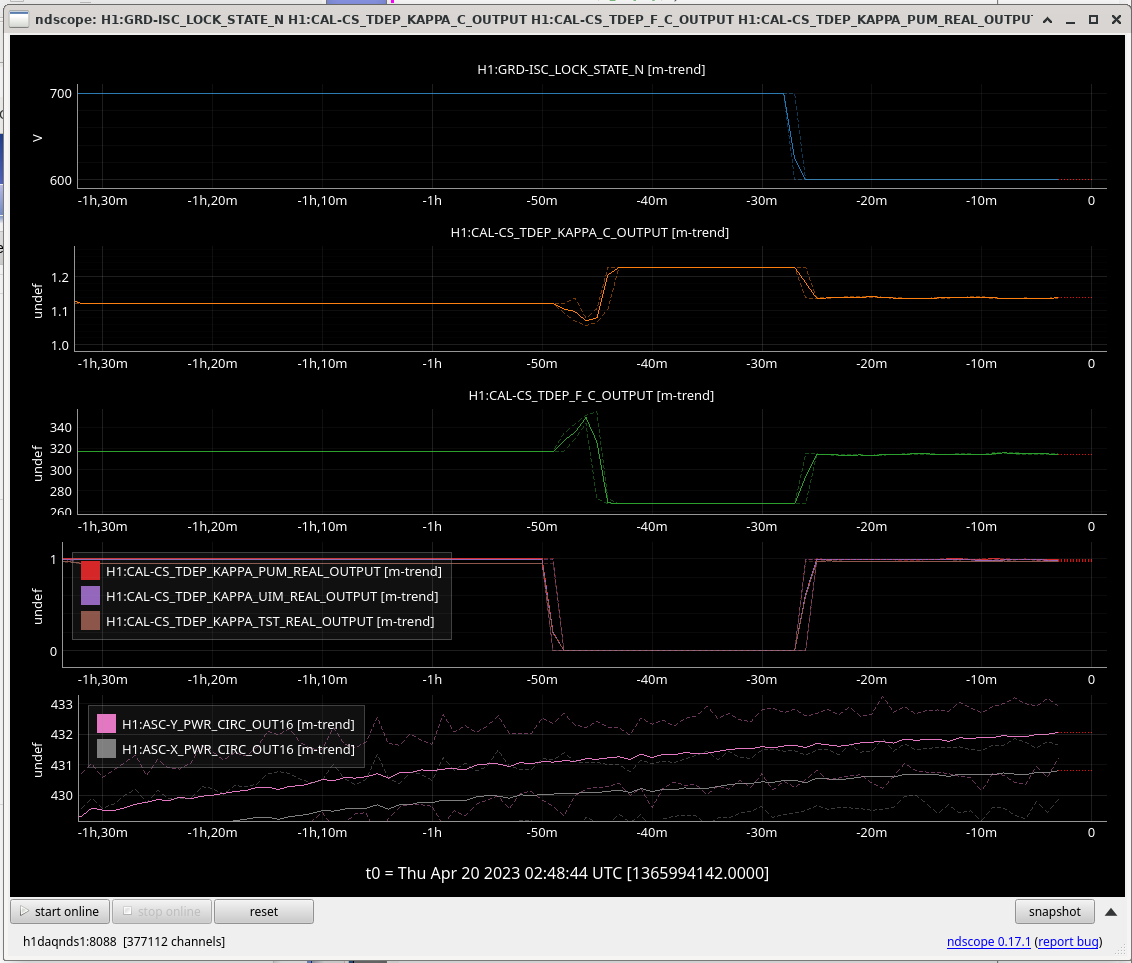
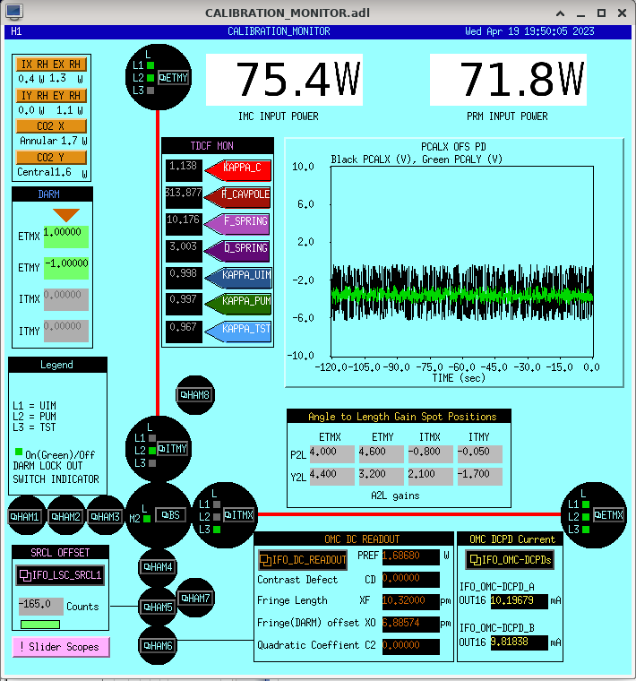
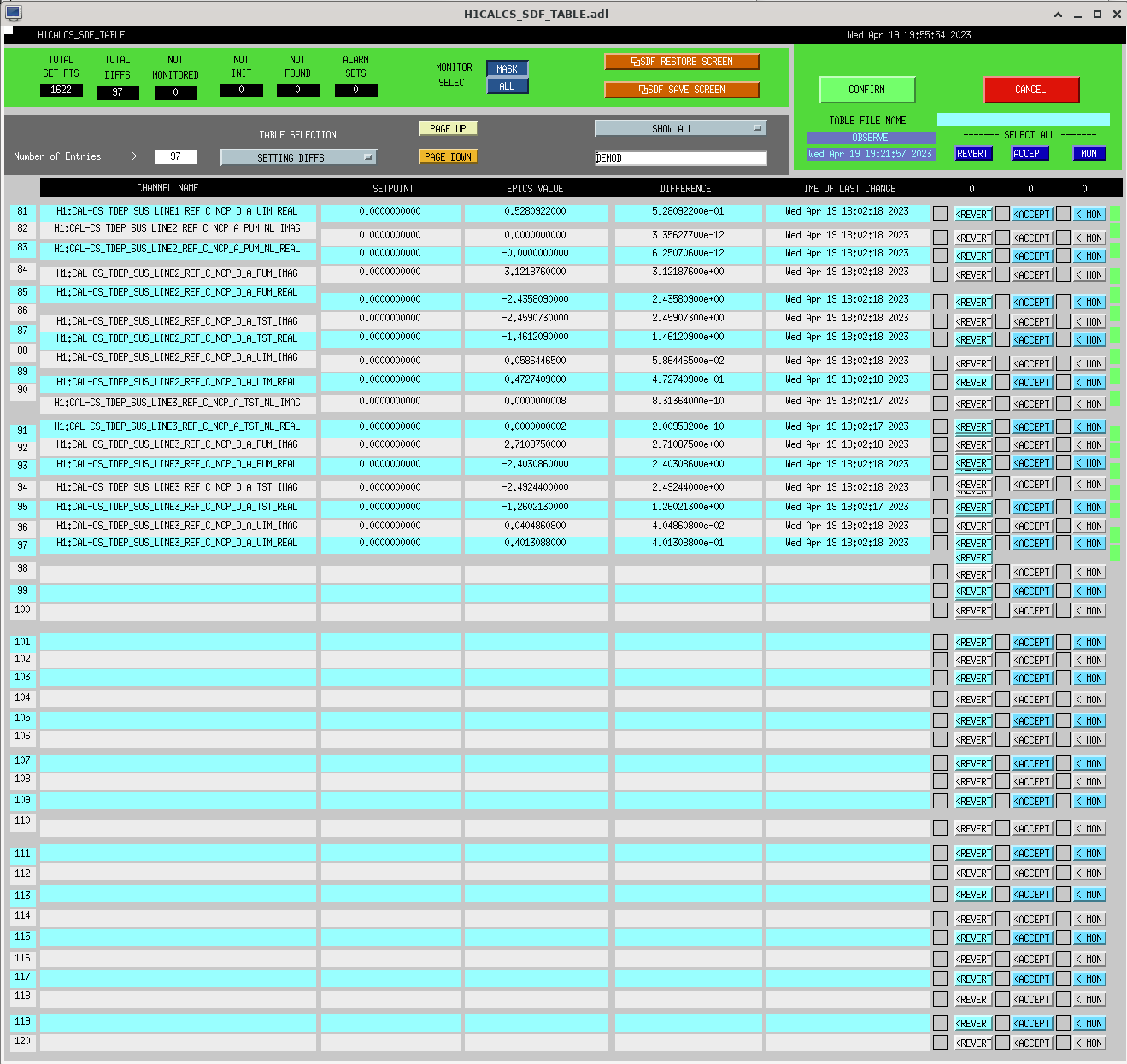
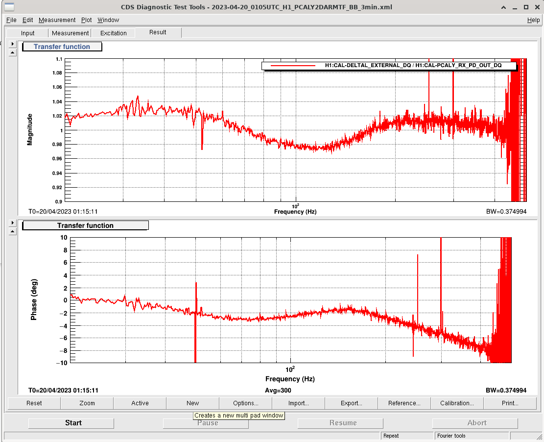
J. Kissel, L. Dartez I updated the calibration usingpydarm exportto push CALCS filter changes and EPICS records for TDCF calculations. The TDCF EPICS records pushed include the new _exact_ TDCF channels that Aaron Viets is testing out. In short,H1:CAL-DELTAL_EXTERNAL_DQis calibrated to within 3% ofH1:CAL-PCALY_RX_PD_OUT_DQin magnitude up to about 450Hz (see syserr.png). However, we've negatively affected the GDS pipeline (see below) and we still need to debug the calculation of the TDCF channels, which are not producing sensible results (see tdep_ndscope.png).GDS Pipeline
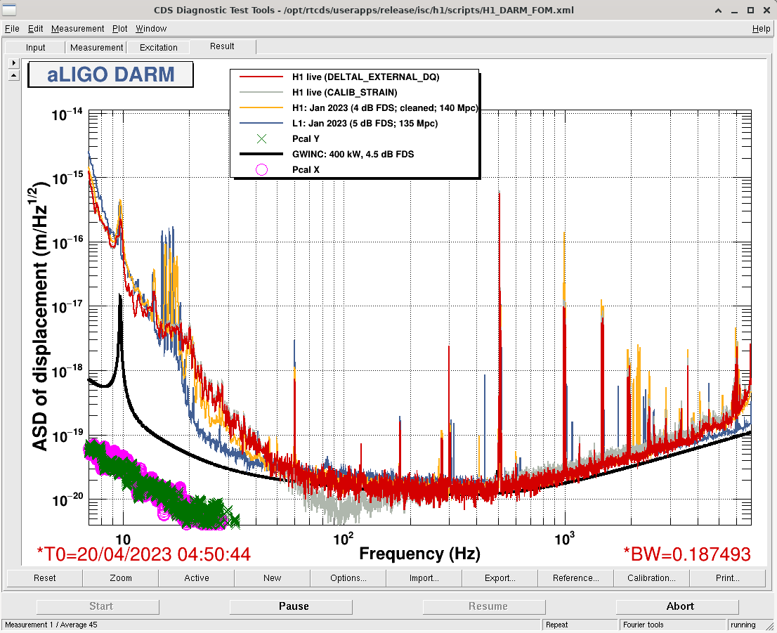
This calibration has introduced a non-physical effect in the GDS pipeline (see darm.png), pointing to an issue with one of the new filter settings pushed today. I'm leaving the calibration up for now since it's decent in CAL-DELTAL_EXTERNAL / the control room. I'm going to be interfacing with the cal group to improve the GDS pipeline calibration and push new settings ASAP.Pcal demods
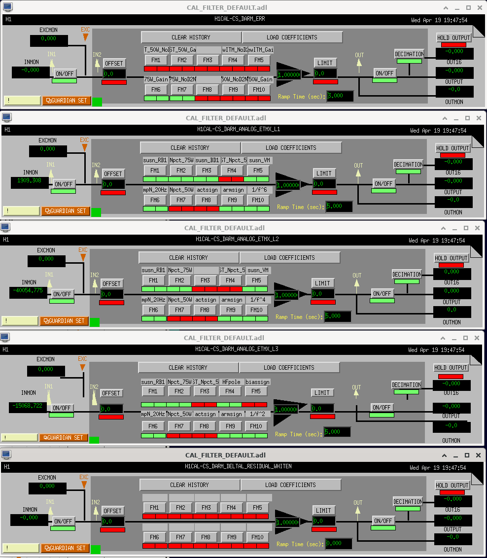
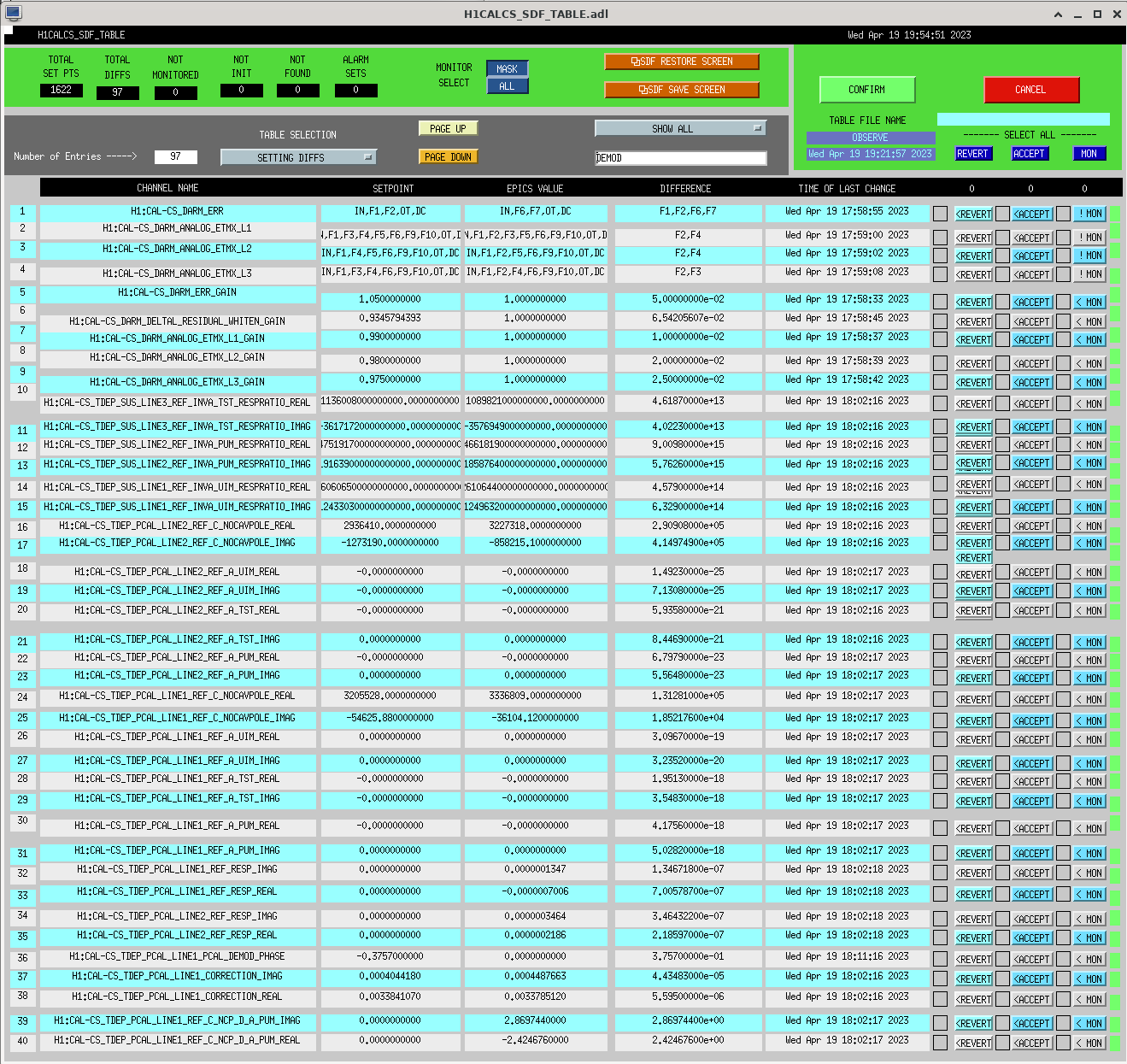
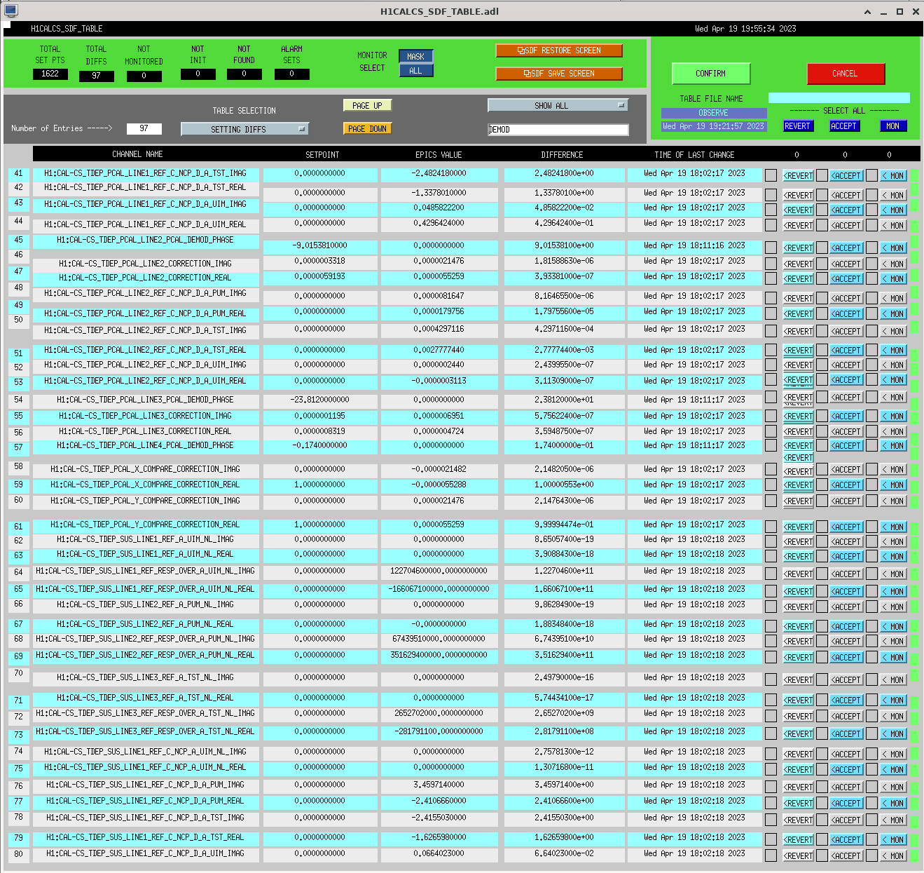
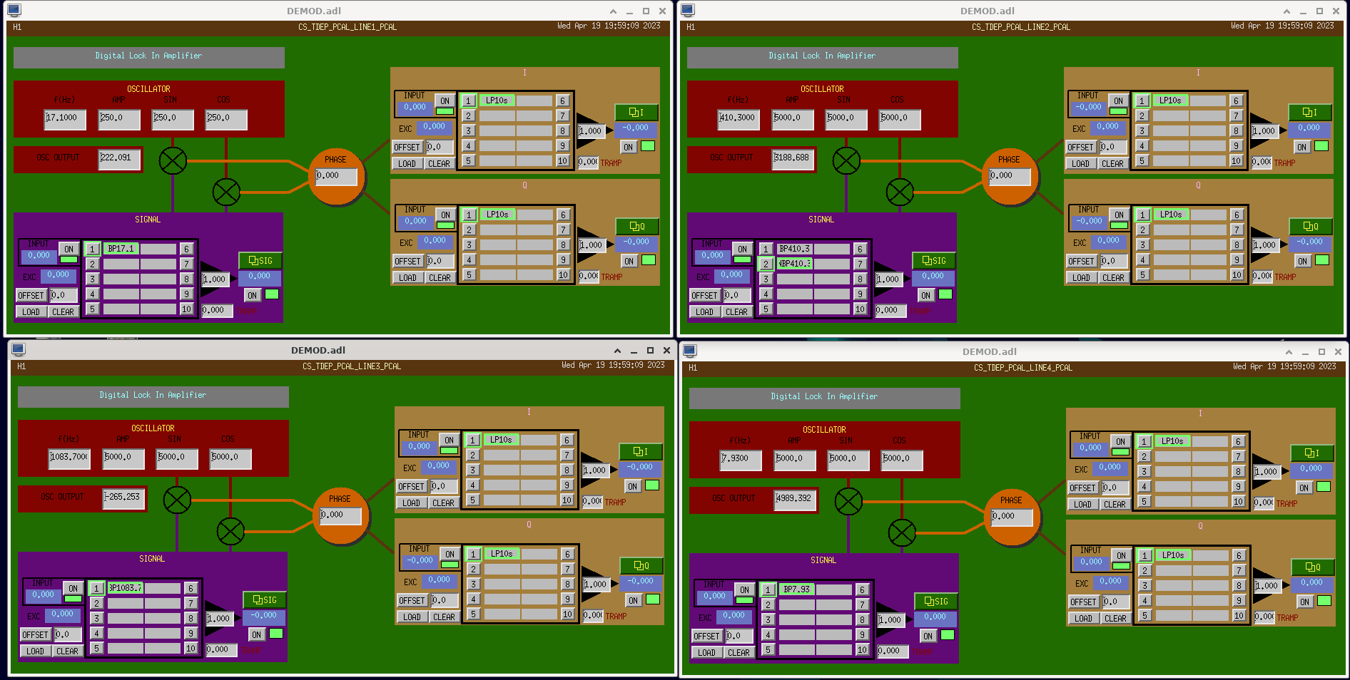
I cleared out the Pcal demods since the phase correction they are meant for is taken care of in pyDARM (throughcalcs.compute_epics_records(endstation=False, exact=True)), see (tdep_pca_demods.png). I've also attached a screenshot of the relevant CALCS filterbanks (filter_after_cal.png), showing that I've cleared the previous fudges. A screenshot of the SDF changes for this calibration update are also attached. The latest pyDARM report, which informed this cal update is attached as a pdf (see H1_calibration_report_20230420T014029Z.pdf).
Jennie, Elenna, Craig
For seven calibration meeasurements over the last two weeks I captured the thermal state of the interferometer, and used the broadband calibration injection taken at that time, and a 10 minute DARM measurement from a nearby quiet time, to get the calibration corrected DARM plots.
The thermal states were captured using thermal_state_capture.py in labutils.
The data was processed using Run_DARM_calib.ipynb in ligo/jennifer.wright/Documents/thermal_state
The BB injection measurements I used are in: /ligo/svncommon/CalSVN/aligocalibration/trunk/Runs/O3/H1/Measurements/FullIFOSensingTFs
The DARM spectra I used for quiet times are in /ligo/home/jennifer.wright/Documents/thermal_state
Calibrated DARM plots are saved in /ligo/gitcommon/labutils/pcal_bb_inj_quick_cal/plots and data is saved in /ligo/gitcommon/labutils/pcal_bb_inj_quick_cal/data
| BB Cal Injection Start | DARM measurement start | Input Power of IFO to nearest W | Guardian State During Quiet time | DARM measurement filename | BB Cal Injection filename | Thermal State Filename |
| 1364697812 | 1364699612 | 60 | 600 | 2023-04-05_0313UTC_H1_DARMSPEC_0-1Hz.xml | 2023-04-04_1945UTC_H1_PCALY2DARMTF_BB_3min.xml | therm_state_1364697812.txt |
| 1364775641 | 1364777441 | 60 | 700 | 2023-04-06_0050UTC_H1_DARMSPEC_0-1Hz.xml | 2023-04-05_1727UTC_H1_PCALY2DARMTF_BB_3min.xml | therm_state_1364775641.txt |
| 1364872253 | 1364871648 | 60 | 700 | 2023-04-07_0300UTC_H1_DARMSPEC_0-1Hz.xml | 2023-04-07_0316UTC_H1_PCALY2DARMTF_BB_3min.xml | therm_state_1364872253.txt |
| 1364882935 | 1364885358 | 70 | 700 | 2023-04-07_0649UTC_H1_DARMSPEC_0-1Hz.xml | 2023-04-07_0612UTC_H1_PCALY2DARMTF_BB_3min.xml | therm_state_1364882935.txt |
| 1365031551 | 1365030706 | 70 | 700 | 2023-04-08_2311UTC_H1_DARMSPEC_0-1Hz.xml | 2023-04-08_2327UTC_H1_PCALY2DARMTF_BB_3min.xml | therm_state_1365031551.txt |
| 1365040525 | 1365039740 | 70 | 600 | 2023-04-09_0142UTC_H1_DARMSPEC_0-1Hz.xml | 2023-04-09_0412UTC_H1_PCALY2DARMTF_BB_3min.xml | therm_state_1365040525.txt |
| 1365385287 | 1365383774 | 78 | 700 | 2023-04-13_0115UTC_H1_DARMSPEC_0-1Hz.xml | 2023-04-12_0145UTC_H1_PCALY2DARMTF_BB_3min.xml | therm_state_1365385287.txt |
I am going to add post some more DARM measurements from other days as I process them.
I plotted all the DARM spectra scaled by the PCAL BB measurement on the same graph, and corrected the parts where the coherence was low to match the unscaled DARM measurement.
Plot is in /ligo/home/jennifer.wright/Documents/thermal_state/pcal_corrected_darm_2023-04-05_0313UTC-to-2023-04-13_0115UTC.pdf
And code is in /ligo/home/jennifer.wright/Documents/thermal_state/Run_DARM_calib.ipynb.
I updated the code to include GPS reference times for the DARM spectra and some additional measurements which were taken on the 10th, 14th and 20th of April.
Code is in: /ligo/home/jennifer.wright/Documents/thermal_state/Run_DARM_calib_20230424.ipynb
Data for broadband calibration TFs to DARM is taken from:
/ligo/groups/cal/data/H1/measurements/PCALY2DARM_BB/
/ligo/svncommon/CalSVN/aligocalibration/trunk/Runs/O3/H1/Measurements/FullIFOSensingTFs/
Data for quiet times:
/ligo/home/jennifer.wright/Documents/thermal_state/*H1_DARMSPEC_0-1Hz.xml
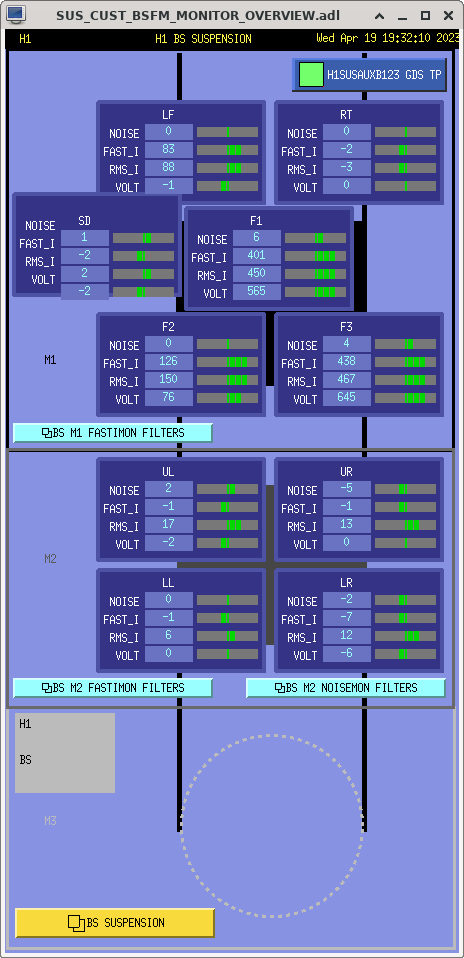
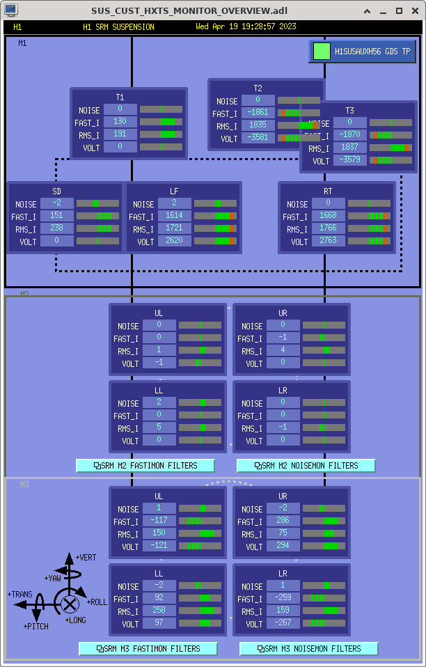
J. Kissel As a fall out of the installation of the newly updated D1900052-style coil driver noise monitor circuits LHO:68796, I've made the effort to understand the frequency response of the circuit (more on this later, but spoilers can be found in G2300866). Now that I have that understanding, I want to calibrate the signals with filters in the front-ends. To do *that* I need (a) easy access to the filter banks to install and turn on that calibration. Once saved in the foton file, I need to *load* those filters, so I need (b) easy access to the GDS_TP screen for the computer that houses these filters. When I arrived at these issues, the coil driver monitor MEDM screens only had easy access to four-channel filter bank screens for the FASTIMON coil driver monitor channels, and no link anywhere to the "susaux" computers that house those filter banks. To solve (a) I've created new four-channel NOISEMON screens, and added links to them on the BSFM and HXTS coild driver monitor screens. /opt/rtcds/userapps/release/sus/common/medm/bsfm/ SUS_CUST_BSFM_M2_NOISEMON.adl # new screen SUS_CUST_BSFM_MONITOR_OVERVIEW.adl # updated to add links to NOISEMON screen and SUSAUX GDS_TP screen /opt/rtcds/userapps/release/sus/common/medm/hxts/ SUS_CUST_HXTS_M2_NOISEMON.adl # new screen SUS_CUST_HXTS_M3_NOISEMON.adl # new screen SUS_CUST_HXTS_MONITOR_OVERVIEW.adl # updated to add links to NOISEMON screen and SUSAUX GDS_TP screen To solve (b), as you can see by the hashtag comments next to the MONITOR_OVERVIEW screens mentioned above, adding links to the SUSAUX computer's GDS_TP screens means I need to edit the macro files for all HXTS and the BS in order to make sure the generic link to the GDS_TP screen works. Every suspension that has coil driver monitors on a separate computer (which is all of them) could use these extra macro variables. But, given that I want to get out of this rabbit hole, I've only done this for the BS and HXTS so far. The following macro files, /opt/rtcds/userapps/release/sus/common/medm/ susbs_overview_macro.txt susfc1_overview_macro.txt susfc2_overview_macro.txt susmc1_overview_macro.txt susmc2_overview_macro.txt susmc3_overview_macro.txt suspr2_overview_macro.txt suspr3_overview_macro.txt susprm_overview_macro.txt sussr2_overview_macro.txt sussr3_overview_macro.txt sussrm_overview_macro.txt now all have new variables AUXFEC, auxfec (upper and lowercase macros for the DCUID for the sus aux computer; e.g. susauxh34 -- covering MC2, PR2, and SR2 -- has DCUID, or AUXFEC=108.), AUXFECNAME, auxfecname (upper and lowercase macros for the computer name; e.g. FC2's coil driver monitor model is h1susauxh8, so auxfecname=susauxh8) These changes have all been committed to the above locations in the userapps SVN. For LLO to import these benign yet very useful updates, just svn up the above mentioned common directories. @opsinfo -- making these same updates for the quad, double, and single MEDM coil driver monitor screens and macros would be some excellent "chair work" if anyone wants to play along with me. Stay tune for more details as I fill out these filters.
From the brute force search for the 3.4 Hz peak it turned out that the peak was dominating PRCL and visible in the PRM suspension signals.
I compared the M1/M3 offloading of PRM adn SRM, that should be nominally the same. I discovered that PRM M1 path has a gain of -0.02, the double of the gain in SRM M1 (-0.01). The offloading filters and the M1 damping filter are the same.
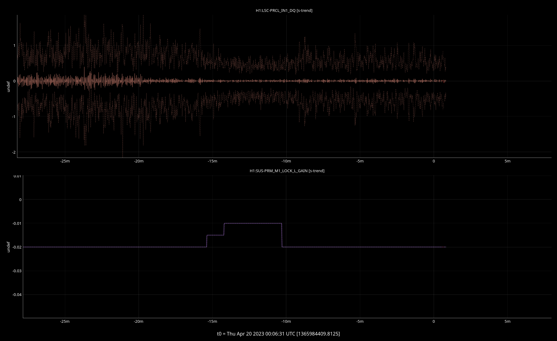
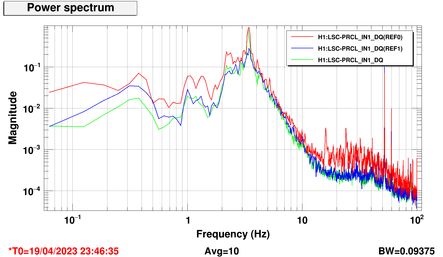
So tried reducing the M1 gain from -0.02 to -0.01. This had a clear and repetible effect on the 3.4 Hz peak. The lower offload gain reduced the peak a lot in PRCL, PRM and in many ASC signals (CHARD_P, CHARD_Y, CSOFT_Y and DSOFT_Y).
The first plot shows the PRCL_IN1 RMS reducing when changing the PRM M1 gain: there is an evident reduction since ther 3.4 Hz peak is dominating the PRCL motion in normal conditions.
The second plot shows how much the peak is reduced by changing the M1 gain: red and green are with high gain (-0.02) and blue with reduced gain (-0.01).
We shoudl measure and retune the PRM M1 and M3 crossover: there is room for further improvement.
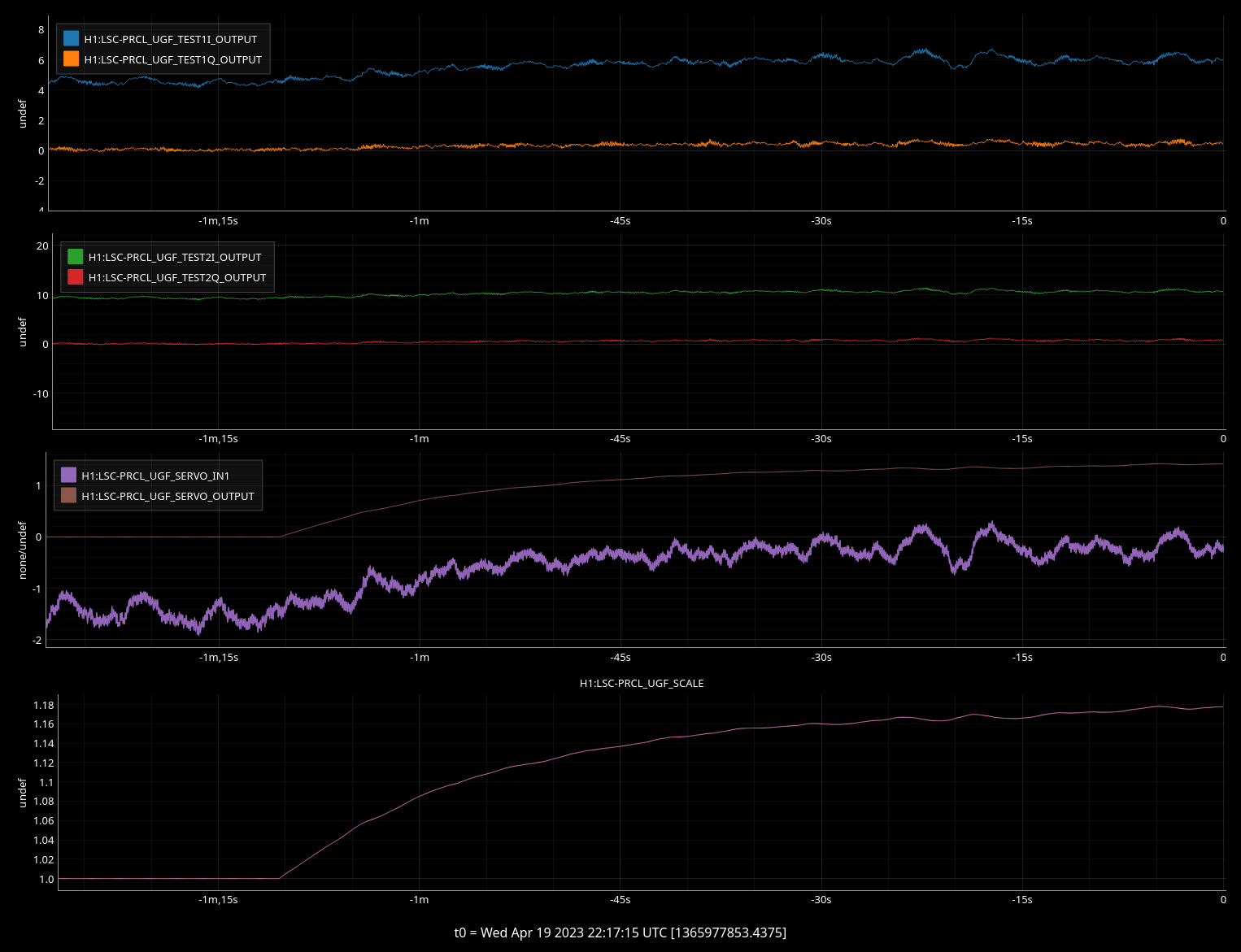
The UGF servo for PRCL is working. For the moment being I'm injecting a line at 52.1 Hz. The plan is to track the evolution of the PRCL gain over a few locks. Hopefully we can then hard code the gain changes over thermalization and get rid of the gain servo.
The servo has a time constant of about one minute.
All parameters have been saved to SDF safe. Except:
Trend of PRCL UGF servo over 1.5 h of lock. Both signals are in db.
It looks like the servo is still too slow to cope with fast changing PRCL optical gain.
The optical gain changed by 6 db over the time in the trend and it's still changing
The PRCL servo is turned on in LOWNOISE_LENGHT_CONTROL and off in DOWN.
We'll leave it on for a few locks to see the trend. We don't want to leave it on longterm, since we are now injecting a huge 52.1 Hz line to measure the UGF.
The H1 DMT system has been experiencing instability since early this morning. This means that the GDS data is not available (via NDS2 or otherwise), including CALIB_STRAIN and the sensemon range. Will report back when the issue has been resolved.
DMT should be recovering. We had to increase the buffer sizes after an increase in the size of the GDS broadcast frames yesterday. Please let the CDS staff know if you see any more issues with the sensemon range of the GDS-CALIB_STRAIN channels.
I spoke too soon, this issue is still being worked on.
ok NOW it should be fixed.
Since this also affects the seismic BLRMS that are displayed on the control room wall, there is an ndscope template available that reproduces the 0.03–0.1 Hz and 0.1–0.3 Hz traces using the front-end BLRMS channels, and hence will stay live even when DMT is down. It lives in userapps under isi/h1/ndscope/Seismic_FOM_STS.yaml (unlike the corresponding DMT file, which lives somewhere in the isc/ directory structure). Right now this needs to be launched with ndscope-dev because it contains a couple labeling features that are not available in vanilla ndscope yet. There are also a couple of pending ndscope features (customizable grid alpha and labelless y cursors) that are not implemented yet to better emulate the corresponding DMTviewer file.
There is not currently an ndscope yaml to replace the 3–10 Hz and 10–30 Hz BLRMS that use the front-end Güralp channels, but one could easily be created so long as care is taken to get the correct calibration into microns per second.
Elenna, Vicky
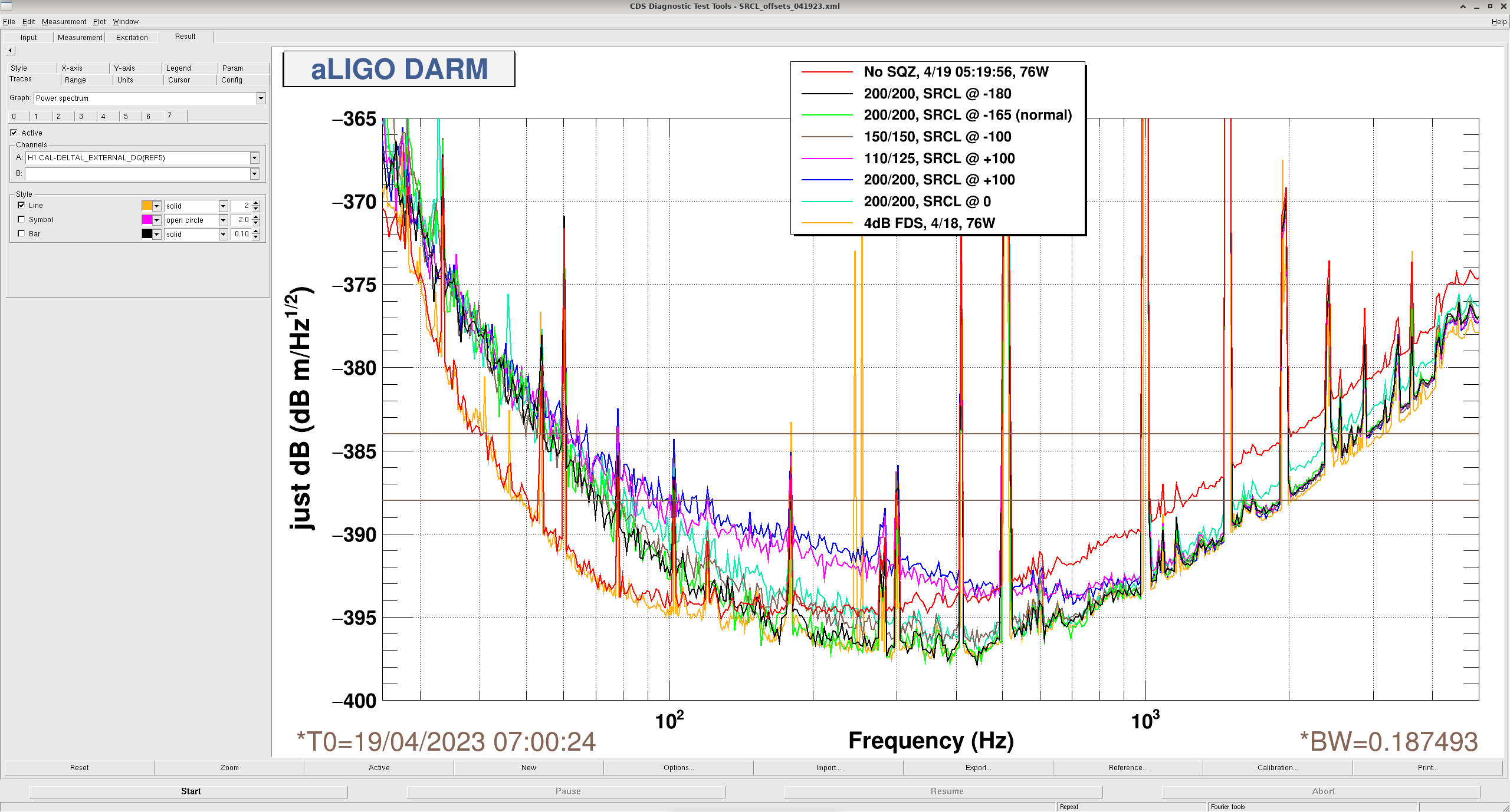
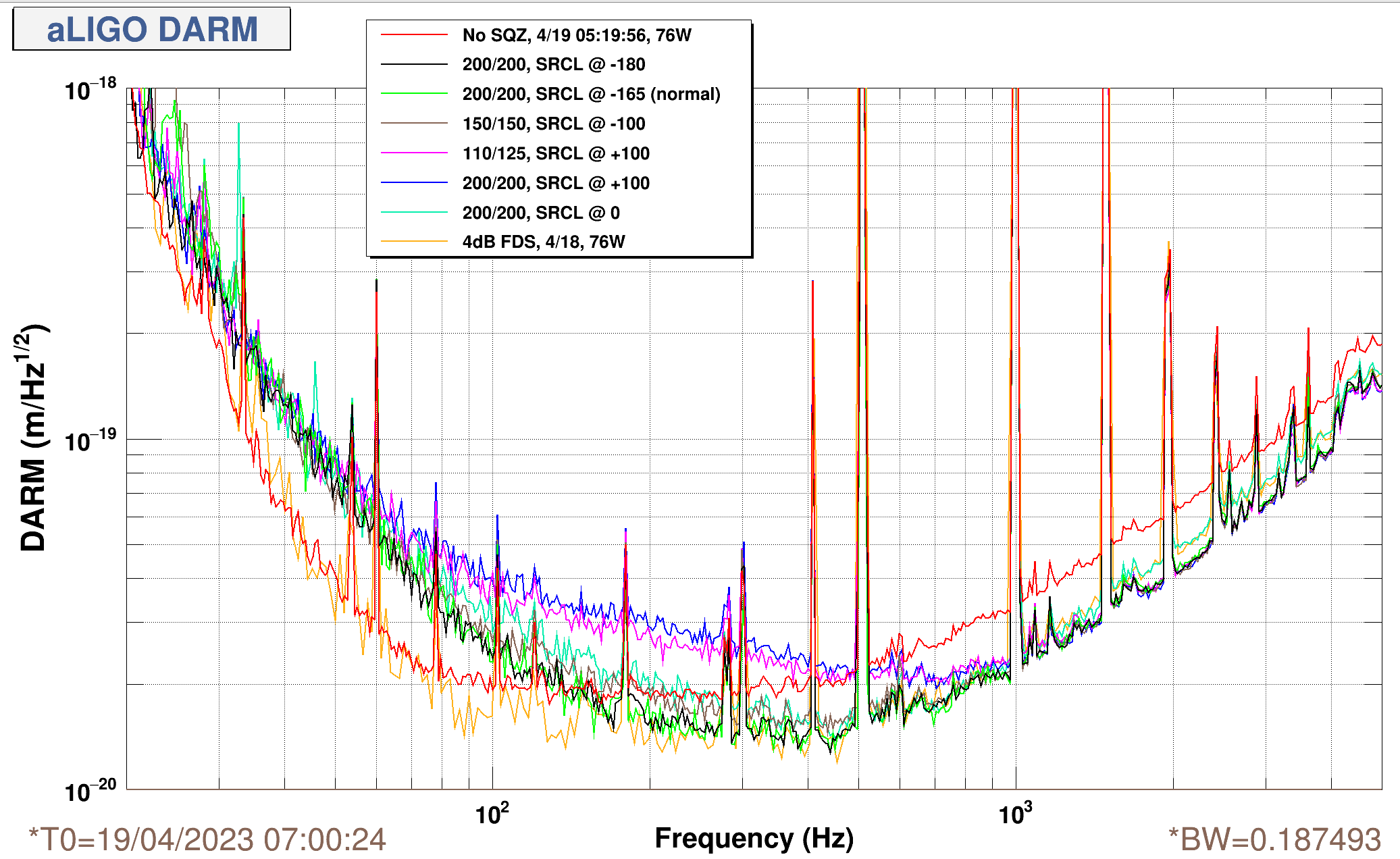
Operating with high generated sqz level ~ 16.5 dB, with IFO at 76W input, ~435 kW circulating, Elenna changed the SRCL offsets and we measured coherent SQZ rotations based on SRCL detuning.
Some takeaways:
Here, at each SRCL offset, we rotate the SQZ angle to be ~0 deg (aka phase sqz) at high frequencies > kHz. And so, we can see how SRCL acts as basically a broadband filter cavity to coherent rotate the sqz angle around the coupled cavity pole. The "SRCL offset" in the plot legend refers to the arbitrary filter bank offset counts, H1:LSC-SRCL1_OFFSET. We did not what physical SRCL detuning (in e.g. degrees) this corresponds to during this squeeze mearement, but this has been measured before at this circulating power. I also tried to explore whether we can see the compounded effects of coherent sqz angle rotations from both SRCL detuning + mode-mismatch together, but this mode-mismatch rotation seems much smaller an effect than SRCL detuning rotations.
Kevin Kuns, Vicky -- The way we see SRCL acting as a broadband filter cavity for squeezing is consistent w/calculations of how SRCL detuning changes sqz angle.
This is not necessarily a problem, as 0 detuning seems good for calibration and us, but it's kinda an interesting effect to see. The SRCL filter cavity action adds coherently with the FC detuning. I'd guess if we're in a bad spot with a big detuning, we could lose some range (guessest'd < 5 Mpc?) due to this misrotation of quantum noise in the bucket. Mostly, it does seem like a large SRCL detuning (like > 0.5 deg) might be non-ideal for squeezing, because FC is too narrowband to undo both significant SRCL detuning and RPN.
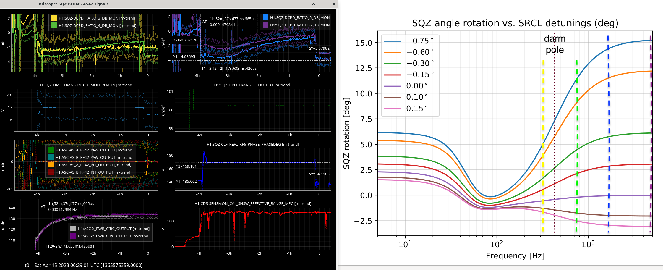
See here: as IFO thermalizes for 2 hours to 430 kW, the amount of high-frequency squeeze angle change (~17 deg) during the first ~2 hours (left) is consistent with Kevin's calculations of sqz angle rotations at various SRCL detunings (right).
Over thermalization, our squeezer band-limited RMS monitors (SQZ BLRMS = H1:SQZ-DCPD_RATIO_*_DB_MON) monitors show drifts of:
BLRMS_3 @ 325 Hz (yellow, below darm pole) ~ 1dB
BLRMS_4 @ 750 Hz (green) ~ 2dB
BLRMS_5 @ 1700 Hz (blue) ~ 3.2dB, ~34/2 = 17 degrees sqz rotation to recover high-frequency squeezing before/after thermalizing. SQZ rotation can be seen on ndscope, last column, 3rd from top (*_PHASEDEG ~ 2x sqz angle).
BLRMS_6 @ 4700 Hz (purple) ~ 2.8dB
High-freq sqz above the DARM pole (~450Hz) sees more rotation as expected, while sqz angle in the bucket is pretty stable w.r.t srcl detuning. We'll generally leave the squeeze angle optimized for the bucket, and let high-freq squeeze thermalize down. So, the sqz angle might look wrong at the start of locks (by ~15 deg, or ~30 deg on our slider).
Interesting alogs related to recent SRCL detunings:
Plot/file attached here in meters/rtHz, sligthly more intuitive to compare with calculations for radiation pressure noise.
Tonight I made a measurement of our contrast defect at 430 kW with the latest ring heater and CO2 settings (using Craig's excellent scripts). ETMX RH: 1.4W, ETMY RH: 1W, CO2s are 1.7W as before.
Our contrast defect is about 2.2 mW now.
This measurement has caused some locklosses. The causes seem to have come from two places: the location of the band stop filters in DARM2 that are activated for the PCAL lines and the tramp for changing the darm offset. Dan put some checkers into the code to check that the bandstop is correct. I ran this measurement using a tramp of 2 seconds that I changed by hand (0.3 seconds causes a large glitch). Before I ran the measurement I checked that at this power and with the high violin modes we could step up to a darm offset of 9 pm. As always, this should be checked before running the code.
Unfortunately the results from this measurement might be a little confusing as they were taken about 1.5 hours after the last ring heater change, and during the previous 3 hours many different ring heaters changes had been made. I will try to redo this when the ring heaters have been more static.
I also made a frequency noise injection last night, right before I made the contrast defect measurement. I have attached the plot comparing the gray trace with past measurements. I made one error: I forgot to turn off LSC feedforward before the measurement, hence the lower noise at low frequency. At high frequency, the noise is not any worse than where we have been operating recently, but not as good as it has been in certain configurations. This suggests we need more CO2 annular tuning perhaps, in addition to improving the ring heater configuration.
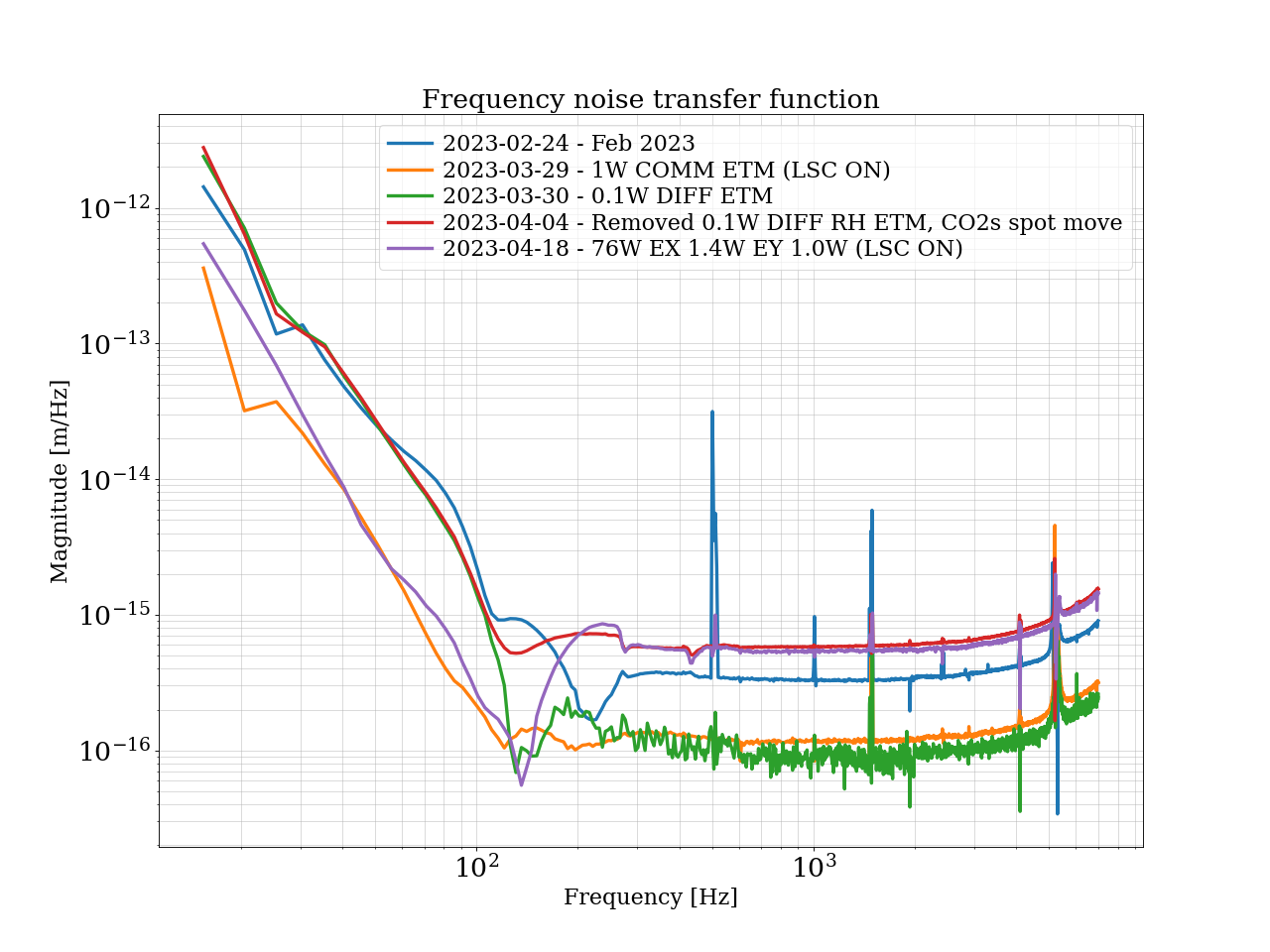
I have generated a more simplified plot that gets across our important TCS and power settings. This is still a bit confusing because some traces have LSC feedforward ON and others OFF. I recommend looking only about 300 Hz at these plots.
Our "best" frequency noise configuration was at 60W input power and 1.1 EX RH and 0.9 EY RH (green trace). However, this was not a workable solution due to PIs, so we stuck with the second best configuration which was 1W each on ETM ring heater at 60W (yellow/orange trace). For both of these settings, the CO2 lasers were misaligned to the beam and set at 4.0W CO2X and 1.7W CO2Y annular heating.
Then, the CO2s were realigned to the beam, and Dan found the best CO2 configuration was 1.7W annular on each. This brought us to the red trace, still 60W input and 1W each on ETM ring heaters. Now we are at the purple trace, so slight improvement from where have been at 60W. Purple is 76W input, with the 1.7W CO2 settings, and ETMX RH set to 1.3 W and ETMY RH set to 1.0 W.
Here is a handy table summarizing all of the details related to the traces in the attached plot. Some of these measurements have contrast defect measurements to match, some do not.
Remembering that the differential ETM ring heater was the most beneficial for our noise, we have decided to target ETMX RH at 1.3 W and ETMY RH at 1.1 W. These values are approximately what you get when you increase the "best" 60W settings by 25%. These are the current settings as of posting this comment.
| Date | Input Power (W) | X arm Power (kW) | Y arm power (kW) | ETMX RH (W) | ETMY RH (W) | ITMX RH (W) | ITMY RH (W) | CO2X (annular) (W) | CO2Y (annular) (W) | Trace color | Notes |
| 2023-02-24 | 60W | 384 | 387 | 0 | 1.4 | 0.44 | 0 | 4.0 | 1.7 | Blue | LSC FF off, 4.7 mW CD, CO2s not aligned to beam |
| 2023-03-29 | 60W | 366 | 364 | 1.0 | 1.0 | 0.44 | 0 | 4.0 | 1.7 | yellow/orange | LSC FF on, CD 1 mW, CO2s not aligned to beam |
| 2023-03-30 | 60W | 365 | 364 | 1.1 | 0.9 | 0.44 | 0 | 4.0 | 1.7 | green | LSC FF off, CO2s not aligned to beam |
| 2023-04-04 | 60W | 368 | 368 | 1.0 | 1.0 | 0.44 | 0 | 1.7 | 1.7 | red | LSC FF off, CO2s aligned to beam |
| 2023-04-18 | 76W | 435 | 437 | 1.3 | 1.0 | 0.44 | 0 | 1.7 | 1.7 | purple | LSC FF on, CO2s aligned to beam, CD 2.2 mW |
It appears that again the best damping settings for ITMY violin mode 5/6 and 8 have changed again. I have not done any testing for what is best, but the current settings are ringing up the modes. I am setting the gains for these modes to zero in the guardian.
However, FM1, 6 and 10 with a gain of 0.1 is working again for ETMY mode 1, so I have updated the guardian accordingly.
I found that FM1, FM2, and FM10 with a Gain of -0.4 works well for ITMY 8 (tested across two locks @ 76 W). Loaded setting into lscparams.
This evening I have been damping ITMY 5/6 using a reduced gain but the same filter settings, FM6 and FM10. Currently both modes are decreasing, according to the narrow band monitors, using a gain of -0.025. I started with -0.01 and ramped the gain up slowly. The broader monitors show mode 6 decreasing and mode 5 staying constant.
Yesterday afternoon I was able to damp IY05/06 using a lower gain (-0.025), even though the lock was not long but still the drive was coming down - see ndscope.