WP12822, Sheila, Camilla
Followed what we did in 82881, but did not need to adjust alignment through the EOM. Last done only ~6 weeks ago in 86323.
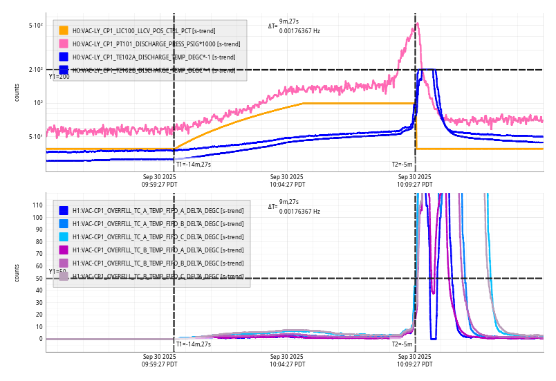
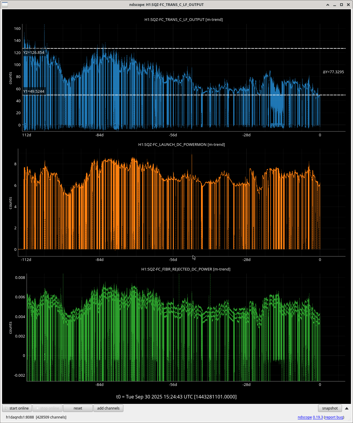
SHG Power dropped when we opened the table and turned on the fan and again when we closed up so we adjusted the SHG TEC temperature twice, it ended up where it started, plot attached.
Starting with:
- 85mW into AOM.
- With 5V on ISS AOM controlmon: 30mW in 0th order and 8.6mW in first order beam.
- With 0V on ISS AOM controlmon: 43mW after AOM
Then with 0V on ISS AOM controlmon, increased throughput, this was a yaw move of the AOM, moving the AOM in +X. Then put 5V on controlmon and started to maximize the 1st order beam. We decided to not completely maximize 1st order as this reduces overall throughput and our current aim is to increase total green throughout, not ISS AOM range.
Ended with:
- With 5V on ISS AOM controlmon: 42mW in 0th order and 9mW in first order beam.
Sheila then adjusted the alignment into the fiber and maximized H1:SQZ-OPO_REFL_DC_POWER (needed to reduce power going into fiber with pico-waveplate to avoid saturating PD).
This allowed us to have an OPO setpoint of 80uW with 25mW going into the fiber, with 5 on the controlmon and a spare~20mW that we could give to the fiber. Note that after ~2hours, the controlmon had decreased from 5 to 4. So the power to the AOM may need to be increased next time we loose lock.
I checked the NLG and OPO temp in the process:
| OPO Setpoint | Amplified Max | Amplified Min | UnAmp | Dark | NLG |
| 80 | 0.0132987 | 0.000179 | 0.0005779 | -1.67e-5 | 22.4 |


