Varun, Stefan
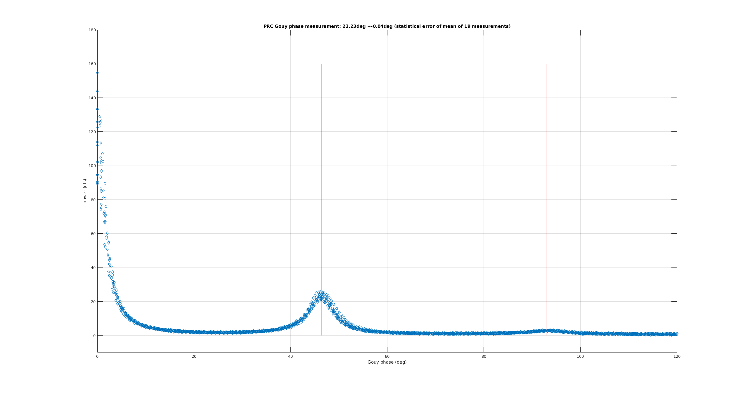
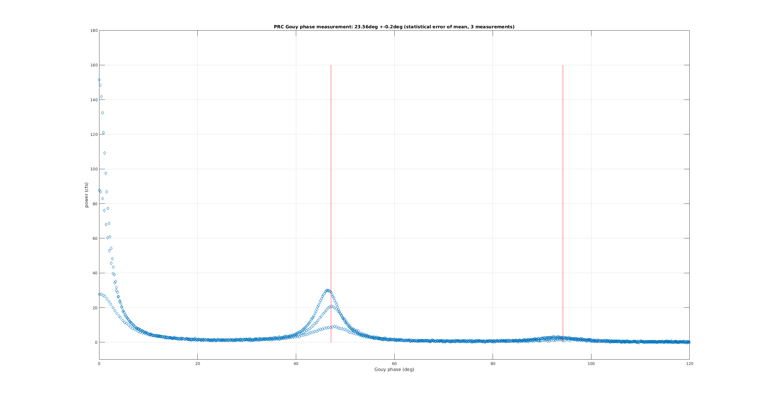
We repeated the PRC Gouy phase measurement that was pinoreered by KAGRA in klog 9241 and 9246.
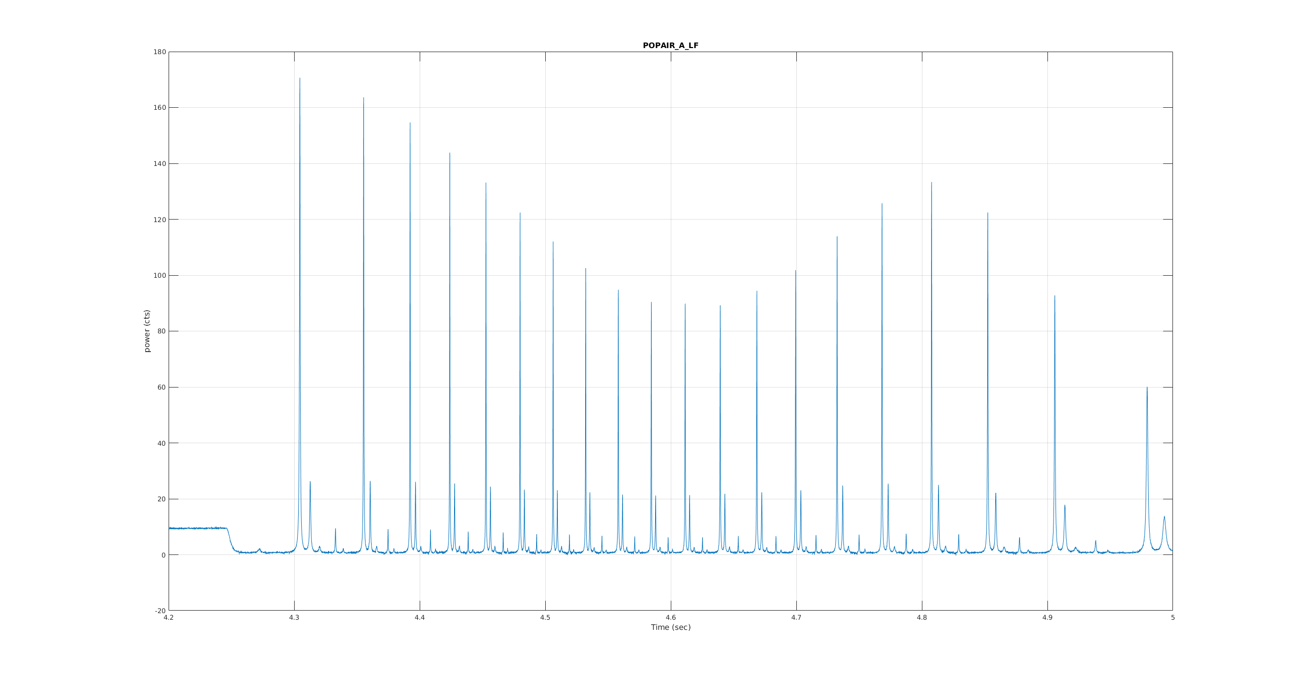
In short, the method consistes for just kicking the PRC mirror out as fast as possible.
We really want to run this method on the SRC, but today only the PRC was available.
When we finally did it right (measurement 2) we scanned acros 19 FSRs. That allowed us to do a very clean spline fit for the velocity.
We find:
PRC one-way Gouy phase: 23.23deg (mean of 19 measurements in 1 sweep).
Standard deviation of data set: 0.17deg
Standard deviation of mean: 0.04deg.
We would not be surprised if there is some systematic error that is slightly bigger. But we would trust the result to about 0.2deg.
Measurement details:
- Measurement 1: We held MICH at its DC control value, but forgot that the LSC trigger cut it off. (Settings: PRCL2 OFFSET: +3e5) (Plot 1)
- Measurement 2: We didn't bother holding MICH, but froze the POP_RF18 output to avoid the LSC triggering to shut off the drive. (Settings: PRCL2 OFFSET: -1e6) (Plot 2,3)
- xml data files and scripts are attached - more details in folder /ligo/home/controls/sballmer/20191015
All day on Oct 15th, 2019, ITMX RH had 0.5W on both the upper and lower segments, ITMY RH had 1.4W on each upper and lower segment, ITMX CO2 had 0.8W and ITMY CO2 had 0.9W. The IFO had not been locked.
Cao, Dan
While installing the phase camera we noticed that the POP beam was being clipped on POP-BS2. After centering it we found we could not realign onto POPAIR B and get similar POP90 and POP18 build ups as we did previously.
Before centering we were seeing POP90~75 and POP18~55, after this was about 35 and 25. We could actually make the build ups significantly higher if we clipped the beam even more, as can be seen in the attached traces. We left the alignment so that the POP beam was not being clipped.
Cao, Dan
Over the weekend we believe we had some grounding issues between the sCMOS camera and the FPGA units we are using, this was causing the camera to glitch and stop communicating every 5-10s. Today we made some electronics to isolate the camera from the rest of the electronics and now it has been running again for several hours with out any issues.
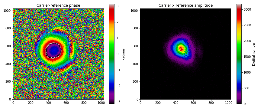
We installed the camera on to ISCT1 with the rest of the setup this afternoon. With PRMI locked, we set the phase camera to image the carrier field and the attached is one of the first images we got. The image attached shows the wavefront of the carrier relative to the reference field. The circular features are because the reference and carrier have a different beam shape. The second image shows us the product of the amplitude and reference amplitudes.
Next we'll work on imaging the other sidebands in an automated way
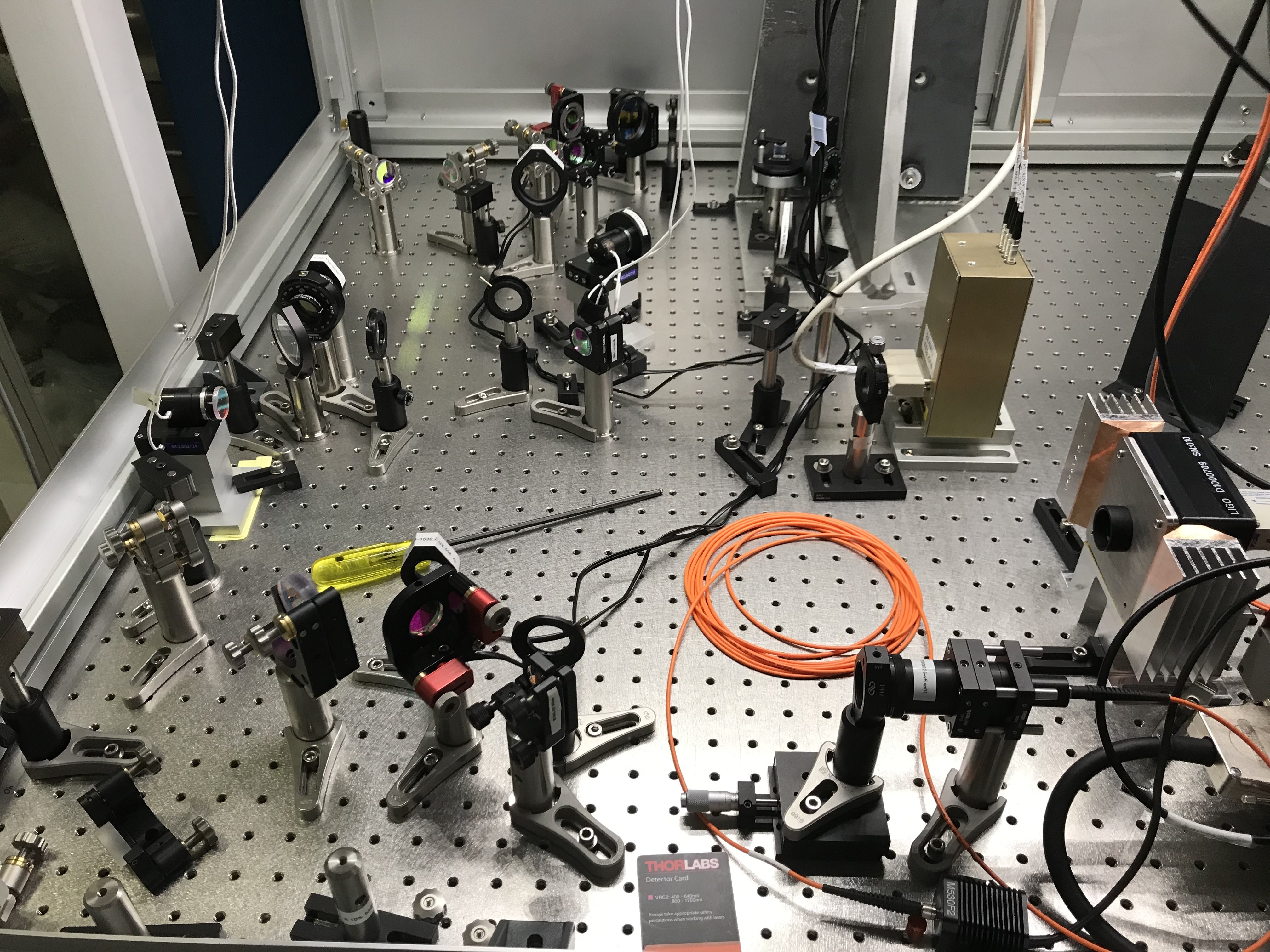
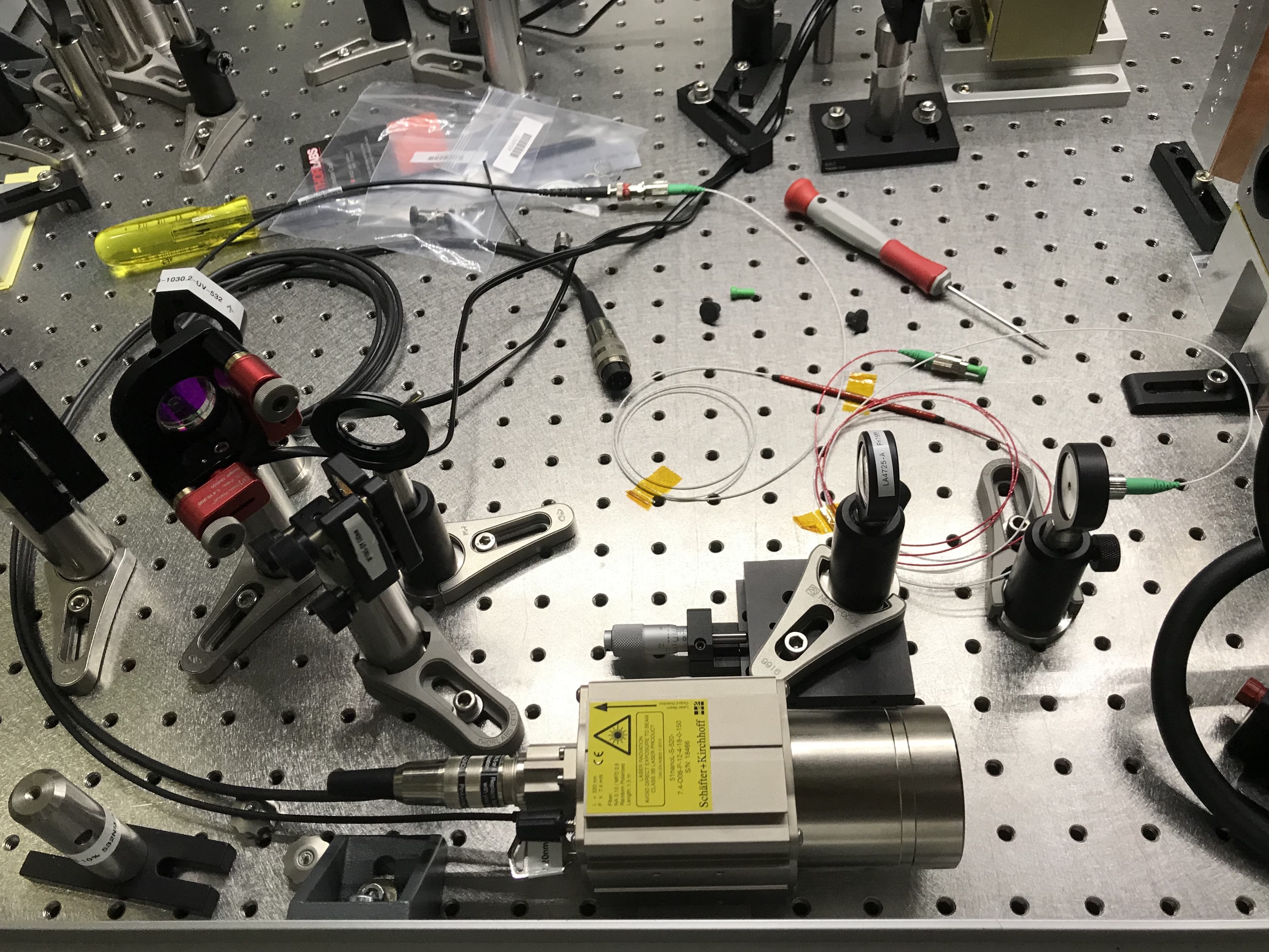
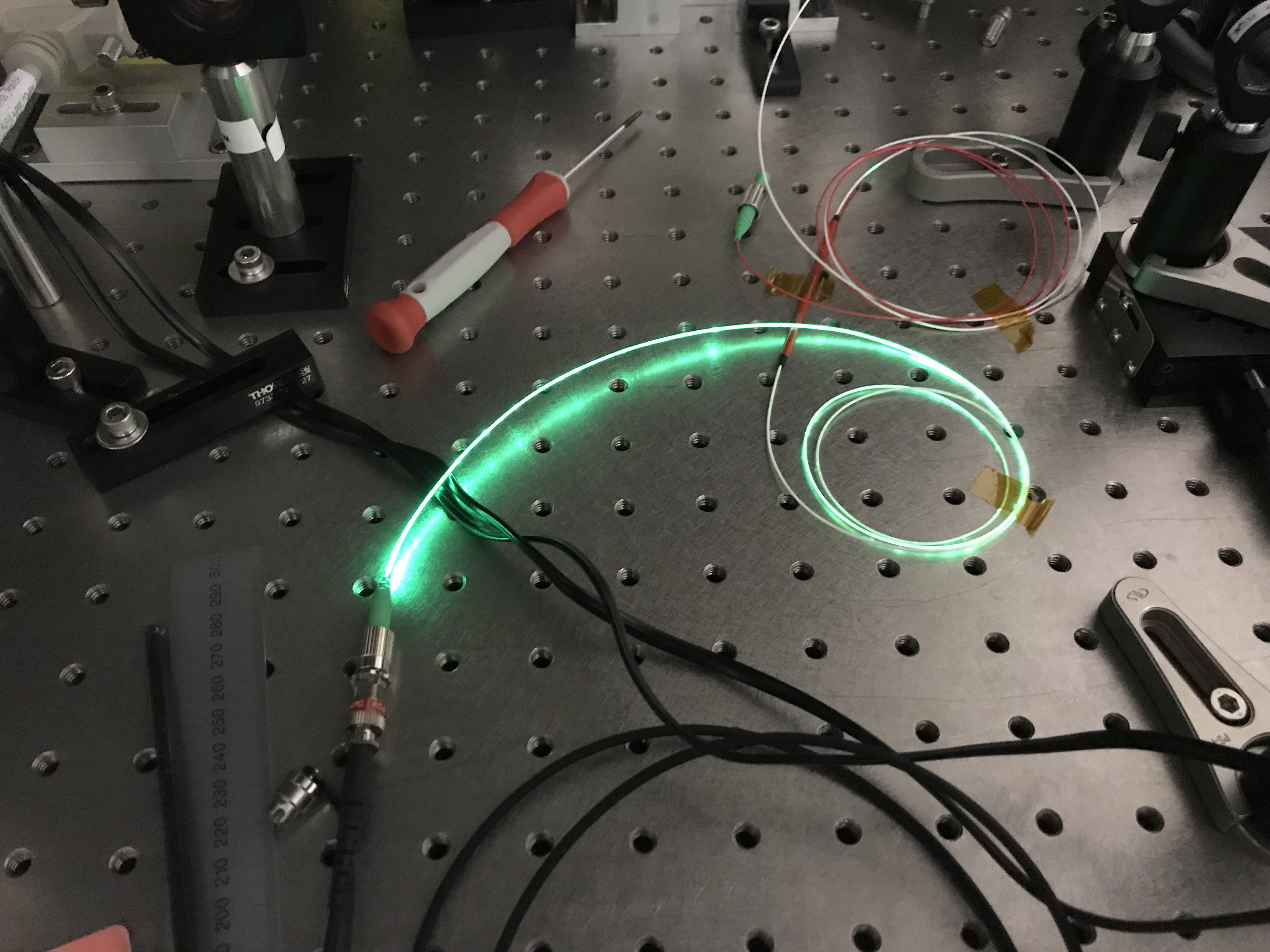
Converted 51nanoL to Class3R by injecting it directly into fiber-coupled splitter. Output power of each port is 0.17mW due to excess insertion loss from FC/PC coupler instead of FC/APC coupler. Expected output power from each port is 2.5mW at 520nm.
1118 - At ETMY, getting set up on go onto ALS/HWS table. ALS laser is OFF. Using T1900654 as guide for work. On table with fan on.
1123 – ETM HWS MEDM screens have reverted to old versions with no control of LED light source.
1132 – Adjusting the launch irises to be centered on the existing HWS beam
1136 – Lens 1 (closest to ETMY): PLCX-50.8-1030.2
Lens2: PLCX-25.4-1030.2
Lens3: PLCC-25.4-257.5
1137 – Distances between optics
LPMtoPBS: 305mm
PBStoM1: 65mm
M1AtoM1B: 113mm
M1BtoM1C: 25mm
M1CtoL1: 83mm
L1toL2: 610mm
L2toM2: 38mm
M2toM3: 67mm
M3toM4: 662mm
M4toM5: 68mm
M5toL3: 261mm
L3toM6: 323mm + 3mm BS
M6toHWS: 629mm
1149 – Summary
LPM to L1: target: 570, measured: 591
L1 to L2: target 610, actual 610
L2 to L3: target 1079, actual: 1096
L3 to HWS: target 903, actual 955
1153 – Removed existing LED source and existing unlabled lens (which looks to be about 120mm focal length)
1207 – Added and labeled new f=75mm collimating lens
1227 – Laser on table and 50/50 coupler installed. Final version should be off-table and in a box that converts it to 3R with a single mode fiber output coupler.
1251 – Laser going through optics. Gets elliptical if collimating lens is twisted.
1303 – Got return beam from ETM. Still need to collimate outgoing beam and image correctly.
----
1519 – Back at ETMY. Going to measure beam profile and beam convergence.
Distance from source to lens L3
TOTAL = 863mm
Adjusting beam from source to converge at a point 91mm past the lens L3
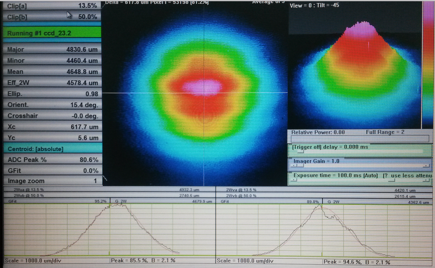
Using beam scan
1544 – Cleaned up beam on BeamScan to be centered in aperture
Looks single mode
Measurement 1: translation stage = 2.62 units
W1 = 6.8mm, z1 = 327
W2 = 5.5mm, z2 = 505
Delta = 7”
Puts focus 395mm past L3
Measurement 2: TS = 3.00units
W1 = 6.79, z1 = 327
W2 = 4.45, z2 = 505
Puts focus -20mm past L3
Suggests going to 2.90 units
Measurement 3 = 2.88units
W2 = 4.82
W1 = 6.86
Puts focus 58mm past L3
USING this
1603 – now adjusting the aligment so it’s centered on the optics
Looks quite large going through the iris on the periscope
1618 – got return beam on HWS
Nominal solution for HWS imaging of test mass (based on measured distances between lenses this is an estimate of how much we need to move the HWS along the optical axis, DZ, to image the ETM onto the HWS)
DZ nominal for HWS = -176mm, approximately 7”
Still a lot of noise on return beam. Adding a 2" beam tube (snout) onto the HWS cut down on a lot of ambient light coupling into the HWS.
Did basic test of imaging by looking at shadow of AERM move as we pitched the ETM. Try to do proper imaging tomorrow.
IO Path images updated with layout and optic identification, added beam profile locations.
Gerardo M., Kyle R.
We started IP10 and let it outgas and stabilize for 30 minutes or so while pumping with the new turbo. We then dumped the unpumped gate annulus volumes of GV14 and GV15 into their adjacent AIP-pumped volumes, isolated the turbo, notified the CR operator of pending BT alarms and then opened GV14 and GV15.
Gerardo M., Kyle R.
Today we helium leak tested the (4) new CFF joints on HAM6, i.e., the new vacuum gauge (2.75" CFF), squeezer fiber feedthrough (2.75" CFF), and the zero-length reducer comprised of 10" and 4.5" joints that the new (baked and leak tested) RGA assembly is mounted to. No leaks were found using the Inficon LD backing the 500 L/S HAM6 turbo - < 7 x 10⁻¹⁰ torr*L/sec background/baseline.
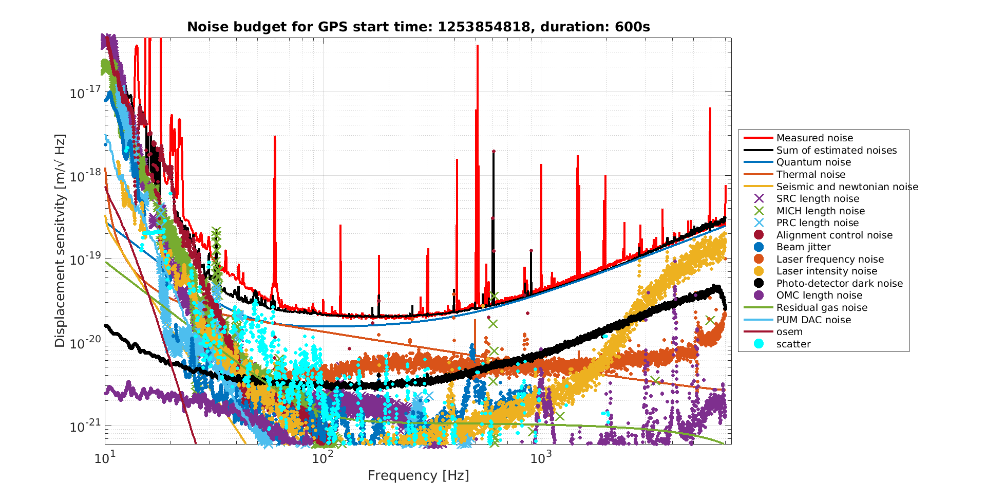
I re-ran the noise bugdet using a reference time after the 48 Hz peak was fixed, which is the same as the BRUCO posted here. I did not re-run any of the coupling or excess power measurements, I only updated the reference time so only traces which have a "live update" are actually changed compared to the previous time we ran the noise budget 51779 The first plot here just shows the noise budget plot for context with the 48Hz peak gone.
The coil driver noise in the noise budget is based on measurements done at LLO of the coil driver noise, propagated by a quad suspension model to DARM. We have been interested in validating this model by leaving the coil drivers in their most noisy state. The second attachment is a projection of how that would impact the DARM noise, the purple trace shows where we would expect that coil driver noise to show up if we were in the highest noise state, which is similar to the level of ASC noise we have (ASC noise is shown for reference). By comparing the blue and yellow traces you can see that if the projection is correct, we should be just able to tell that there is a change in noise when we put the coil drivers into their noisiest state, so this test is worth a try.
The third attachment contains projections of the DARM noise and range gains possible by improving some known noises in our noise budget. The upshot is that we could improve by a few MPc by increasing the input power (if recycling gain and cavity pole stay the same) and by a few more with improved squeezing. Reducing LSC and ASC noise don't help much in range but the ASC noise is probably still worth working on because it may not be too hard to get back to ASC noise levels similar to what we had in O2. The main message is that we need to keep working on candidates for low frequency noise that aren't in the noise budget, (scattered light, output jitter).
WP 8382
All cabling for the BRS Heater installation have been pulled at EX. New Bechoff modules and heater driver chassis are now powered on.
To align the beam on the AS_AIR camera on ISCT6, Sheila and I slid the periscope ~1 inch, to compensate for the new ISCT6 position.
We did this to help with PRMI locking attempts this afternoon.
Philippe N, Corey G
Finished winding the last few turns of the EX coil after a broken wall bracket was fixed (52402). EY brackets are ready for coil winding.
After verbal chats with RichardM and Betsy, I enabled the PSL rotation stage.
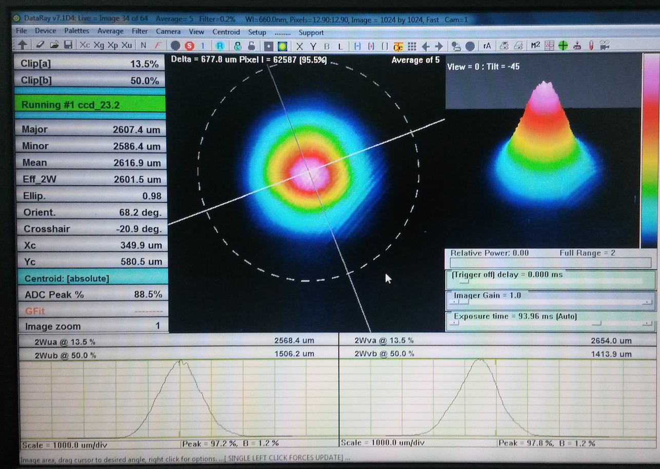
Starting where I stopped yesterday, I continued to adjust the mode matching lenses. Unfortunately, no matter how I adjuted the lens positions I could not improve the power transmitted through the PMC. Therefore I returned the lens positions to where I started this morning (same as where I ended yesterday).
I believe the degradation in PMC Trans is due to a slight alignment shift through the 70W amplifier. I base this on the beam profile I took yesterday. When compared to the one from November 2018 (the last time we tweaked the alignment through the 70W amp) the beam is not as round as it was. Last November the horizontal beam width was 0.69% larger than the vertical; now the horizontal beam width is ~3% larger than the vertical. In addition, the halo around the beam is brighter than previous. To fix this we would need to realign the beam through the amplifier, which would then cause a full realignment of the beam path from the 70W amp to the PMC; this would interrupt all work on the IFO for a few days (PMC and FSS unlocked, ISS AOM removed for alignment). Before launching on this I spoke with Betsy and Keita. We decided that there was no rush to launch on this effort for a few reasons:
So, that's where things stand right now. While we are seeing less light through the PMC, this is not a critical issue worth bringing other necessary work to a stand-still over. I will continue to monitor the PMC and will continue to take necessary preventive maintenance actions when required. Thus ends the H1 PSL work for the October 2019 break.
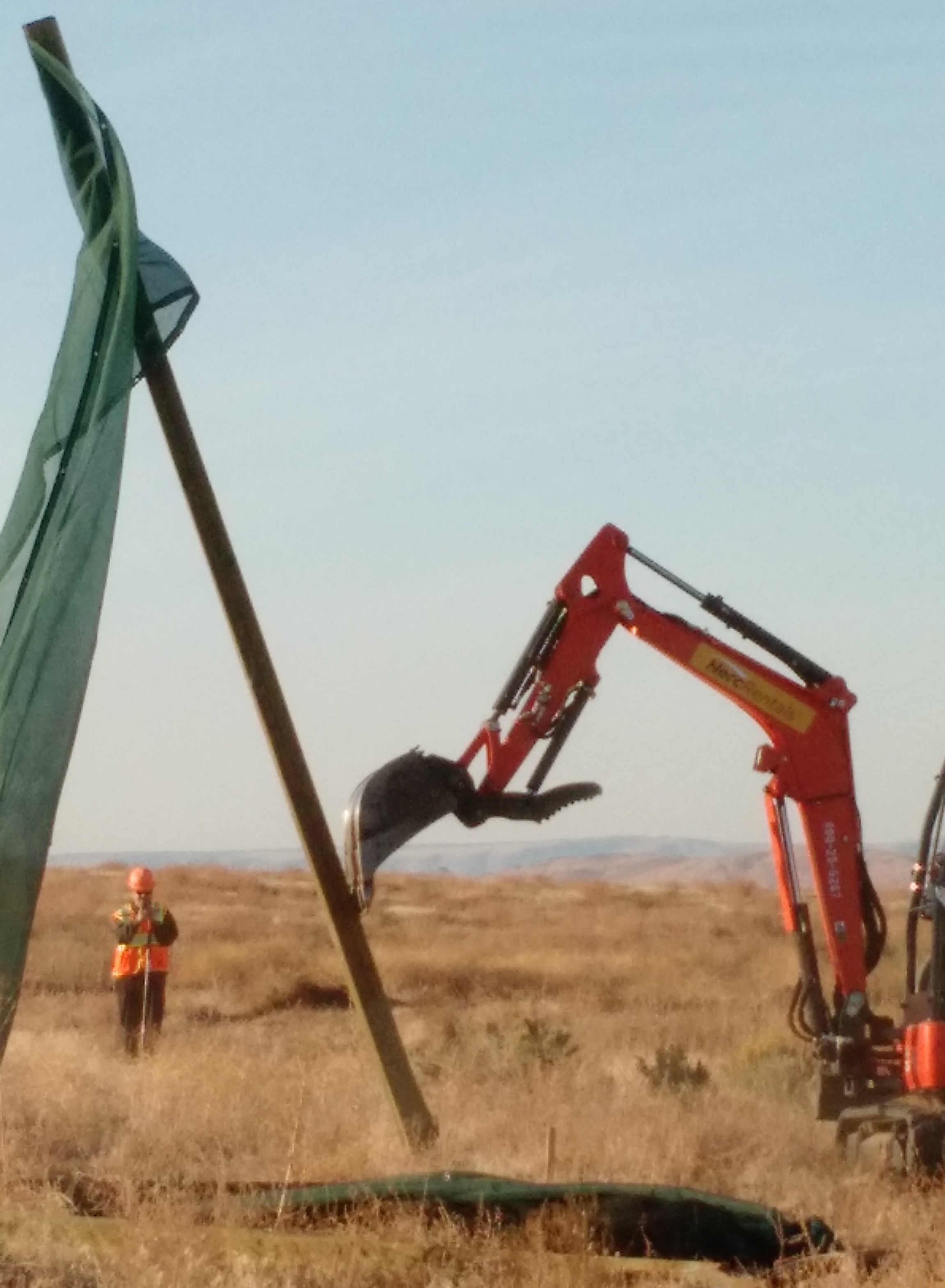
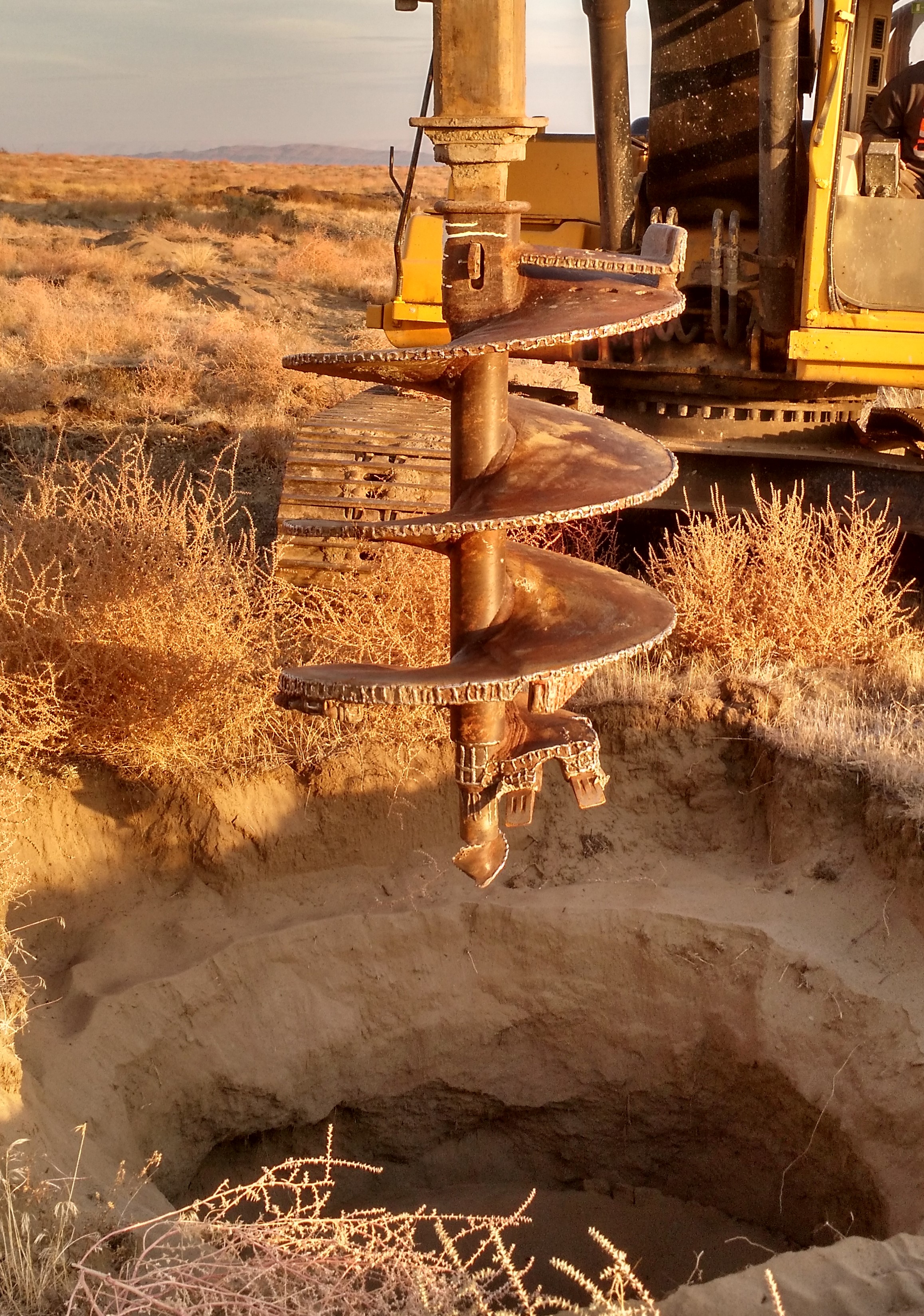
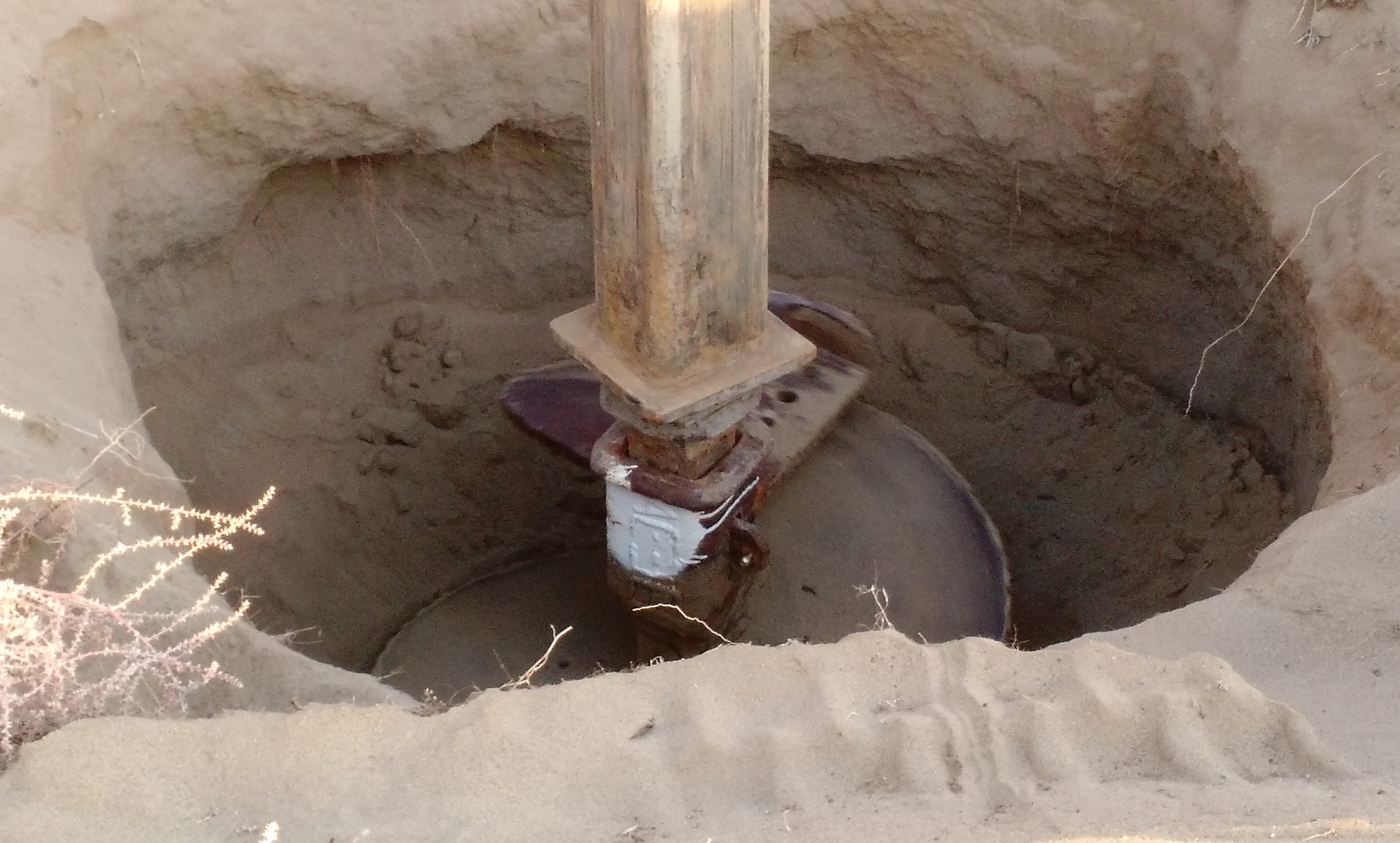
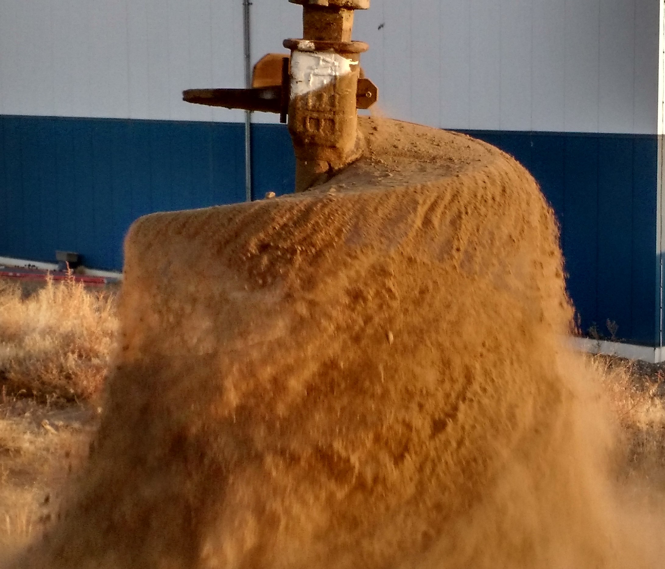
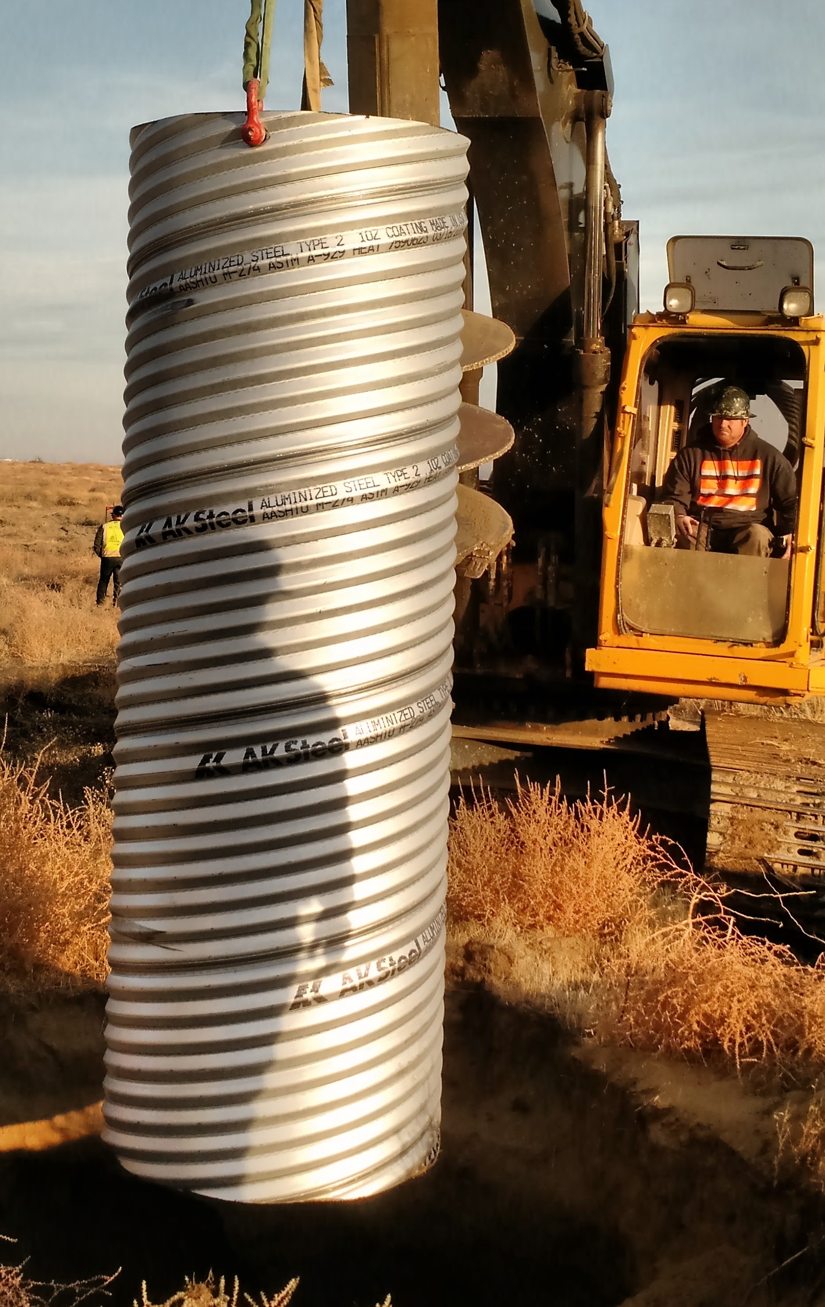
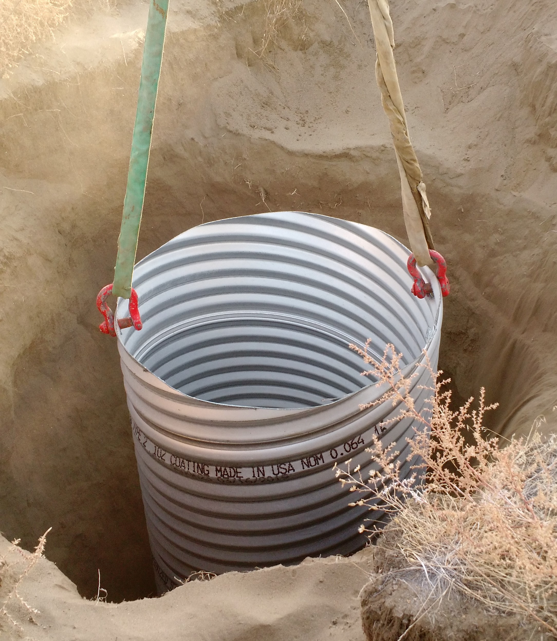
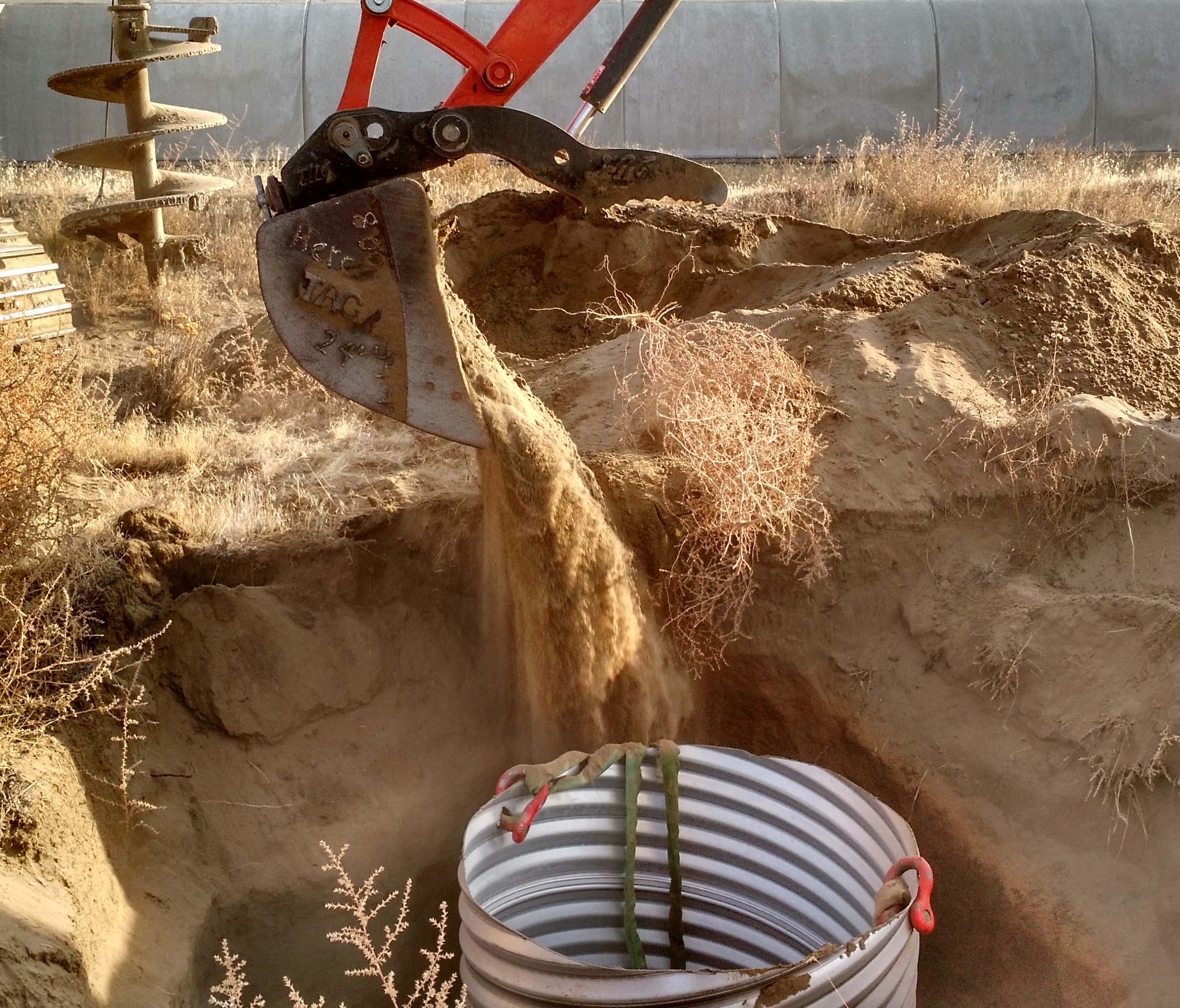
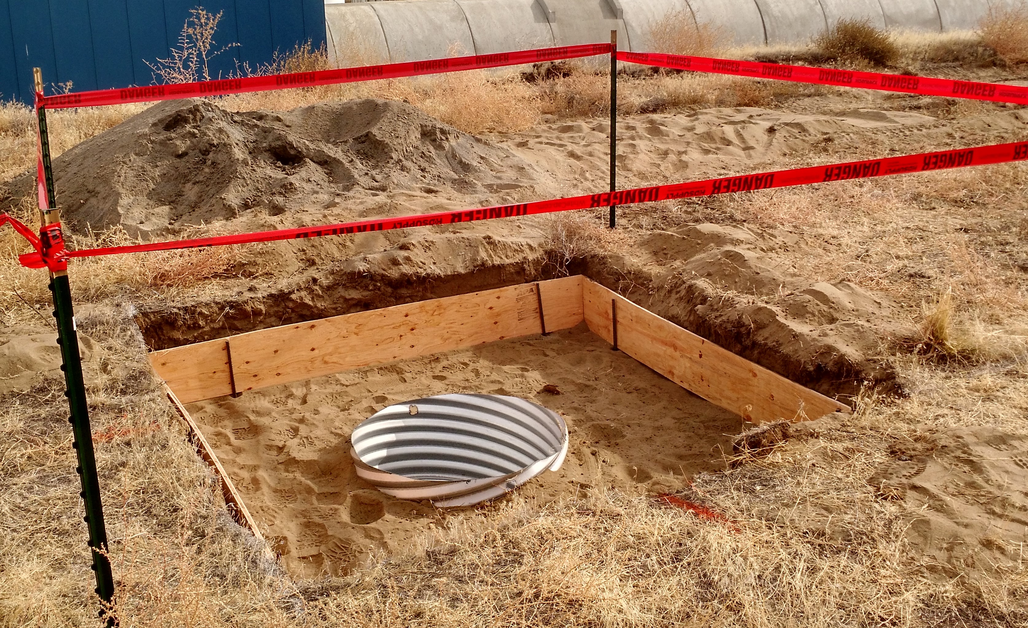
Attached are some images. 1) the old fence posts go away. 2) The Tool. 3) In the hole. 4) Get rid of dirt. 5) In goes the casing. 6) Casing down in the hole. 7) Back fill around casing. 8) Formed and ready for pole.
Suspect they will be done at End X shortly. The drill machine won't move until Wednesday morning as it needs a low-boy trailer that is elsewhere for now.
The caisson holes at EndY will be worked on this afternoon. The drilling at EndY while deeper should have little problem finishing Wednesday unless down-hole condition are quite different from EndX.
Chiara, Jenne, Jim W, Dave:
WP8410 HAM ISI IPC, PROC Filter matrix
The following models were modified and restarted: h1isiham[2-6], h1seiproc, h1oaf.
Model changed included adding new IPC senders (29 added), new IPC receivers for all models except h1oaf, and a filter matrix for h1seiproc. The latter two result in a new DAQ ini file, and therefore DAQ was restarted following the model restarts.
Checked the HEPI pump stations at both end stations and in the corner. All are looking good. No new fluid leaks noted and known leaks show no changes from last checks. Fluid Levels: End-X 8 15/16 down 1/16" End-Y 7 14/16 NC CS 6 6/16 NC Closing FAMIS #13488
{Bubba, Tyler, Chris, Chandra}
Removed the north door on HAM12 and currently storing on door hanger. We temporarily covered the HAM flange with a C3 soft cover. Plan to cap the septum plate with the three blanks that Gerardo found today. We will leave HAM12 stored up to air with C3 covers in place of doors. Meanwhile Bubba ordered 92.25" shipping covers for HAM11 to preserve HAM 7,8,9,10 vacuum surfaces in dry air.
This HAM12 door has some sratches along outer o-ring seal surface. Scratches are not new; we suspected an outer o-ring leak somewhere in HAM 11, 12 based on annulus ion pump behavior. Stoning technique may smooth them out.
Additional photos here.
(Corey G., Philippe Nguyen, Gavin Wallace)
Continued Magnetic Coil installation at EX from yesterday. We improved on our technique and got quite a ways done in an hour. Unfortunately, we had to stop work because we noticed one of the upper corner brackets came undone from the wall (there are a total of 4 screws which are holding these brackets and one of them partially popped out from the wall). This occurred as we were pulling down on the cable to remove any slack in the loop. We notified Richard about this and he mentioned that he will get Ken to re-secure this bracket.
As for status of the coil, we counted how many loops we were able to make, and we had about ~75 turns (LVEA one has about 80 turns), so we we were almost done with using the 2nd spool of wire.
Ken repaired the upper left corner bracket this morning.
This is a continuation of alog 48366. I tried fitting the Ward DARM model to the "2019 08 19 August Spots No SRCL Offset" DARM plant measurement. I thought SRC losses might be sufficient to explain the lowering of the Q of the DARM spring resonance. While the SRC losses do lower the DARM spring resonance, it also lowers the DARM pole frequency, as is expected (fDARM = farm (1 + rSRM)/(1 - rSRM)). The level of SRC losses needed to explain the lowered DARM spring Q is far too high to be realistic (~10-15%). These sorts of losses would lower the DARM pole far too much (~310 Hz for 10% losses). Allowing an MCMC to try to fit the Ward model to the measurement produces the pdfs below.Fit Parameters: Phi = Detuning Angle ~ 89.5 degs Zeta = Homodyne Angle ~ 90 degs Pbs = Power on the Beamsplitter = Input Power * PRG ~ 32 * 44 = 1.4 kW Losses in the Arms ~ 100 ppm Losses in the SRC ~ 1 % ?? Losses in the OMC (including OFI, tip-tilts, etc) ~ 10 %The walkers want to lower the DARM spring Q by reducing the power on the beamsplitter and lock at some incorrect homodyne angle. The power on the beamsplitter the MCMC wants is far too low (PRG would be ~30). In the posted corner plots, I have plotted my "initial guess" parameter values as the red lines. We trust the homodyne angle and power on the beamsplitter guesses here pretty well, but the losses guesses are not well-informed. The priors on the parameters are-90 < phi > 270 [degs] 85 < zeta > 95 [degs] 0 < Pbs > 2000 [W] 0 < arm_loss > 500e-6 0 < SRC_loss > 1 0 < post_SRM_loss > 1SRC losses were implemented as scattering losses in the SRC, i.e.TSRM = 32%, RSRM = 1 - TSRM - LSRC. Dan Brown has produced a Finesse model of this same effect, with similar results to be reported soon. We are in the process of checking the overall gain of the Ward model versus the Finesse model. Relevant code lives in the darmplant git repo.
Quick update: I've taken a look at Dan Brown's code, and we've gotten a decent agreement between the finesse model of LHO and the analytic Ward model. Starting from Eq 3.83 of Rob Ward's thesis, we multiplied E_zeta by E_LO to get watts of DARM response, where E_LO = sqrt(20 mA/resp/QE), where responsivity = 0.856 A/W, and quantum efficiency QE = 0.98. 20 mA is the amps on the DCPD sum which is servoed using the DARM offset. Using the same parameters in the Ward model and Finesse, I put in an additional overall scaler of sqrt(2) into the Ward model to get a overall gain matchup. Unclear where this factor is coming from yet. Parameters used for comparison: Phi = 89.35 deg Zeta = 90.0 deg E_LO^2 = 0.0238 watts L = 3994.4692 m ls = 56.01 m T SRM = 0.32 T ITMX = 0.015 T ETMX = 5e-06 Pbs = 1417 W Arm Loss = 9e-05 SRC Loss = 0.05 Talking to Dan, the small wiggle at 4 Hz comes from a small MICH offset. Remains to be seen if a larger MICH offset (which could be believable given the ~0.6 degree SRCL detuning we see nominally at LHO), could explain some of these discrepancies.
btw i found the factor of sqrt(2) it comes from the definition of quadratures in Buonanno and Chen 2001, they define their quadratures like (a(w) + a^*(w)) / sqrt(2). if you want to measure actual sideband power fluctuations at w you have to include the sqrt(2) when returning to real units of watts.