TITLE: 04/12 Day Shift: 15:00-23:00 UTC (08:00-16:00 PST), all times posted in UTC
STATE of H1: Earthquake
OUTGOING OPERATOR: Cheryl
CURRENT ENVIRONMENT:
Wind: 12mph Gusts, 6mph 5min avg
Primary useism: 0.33 μm/s
Secondary useism: 0.24 μm/s
QUICK SUMMARY: More EQs still arriving. Earth is angry this morning.
On Tuesday we increased the mx_stream delay for h1susauxh34 from 1mS to 3mS. At 04:29:09 and 04:29:31 PDT this morning we got 5 CRC errors in total. I have just increased the delay from 3mS to 5mS while H1 is unlocked and reset the CRC counter to zero.
TITLE: 04/12 Owl Shift: 07:00-15:00 UTC (00:00-08:00 PST), all times posted in UTC
STATE of H1: Earthquake
INCOMING OPERATOR: Travis
SHIFT SUMMARY: Great until a series of EQs
LOG:
| Origin Time UTC |
Mag | Latitude degrees |
Longitude degrees |
Depth km |
A M |
Flinn-Engdahl Region Name | |
|---|---|---|---|---|---|---|---|
| 2019-04-12 14:51:30 | 5.6 | 6.56°S | 148.60°E | 10 | A | New Britain Region, P.N.G. | |
| 2019-04-12 14:28:41 | 4.7 | 14.12°N | 51.62°E | 10 | A | Eastern Gulf of Aden | |
| 2019-04-12 12:23:07 | 6.0 | 15.34°S | 173.01°W | 33 | A | Tonga Islands | |
| 2019-04-12 12:12:13 | 5.1 | 1.80°S | 122.69°E | 10 | A | Sulawesi, Indonesia | |
| 2019-04-12 11:40:49 | 6.7 | 1.88°S | 122.60°E | 10 | C | MT | Sulawesi, Indonesia |
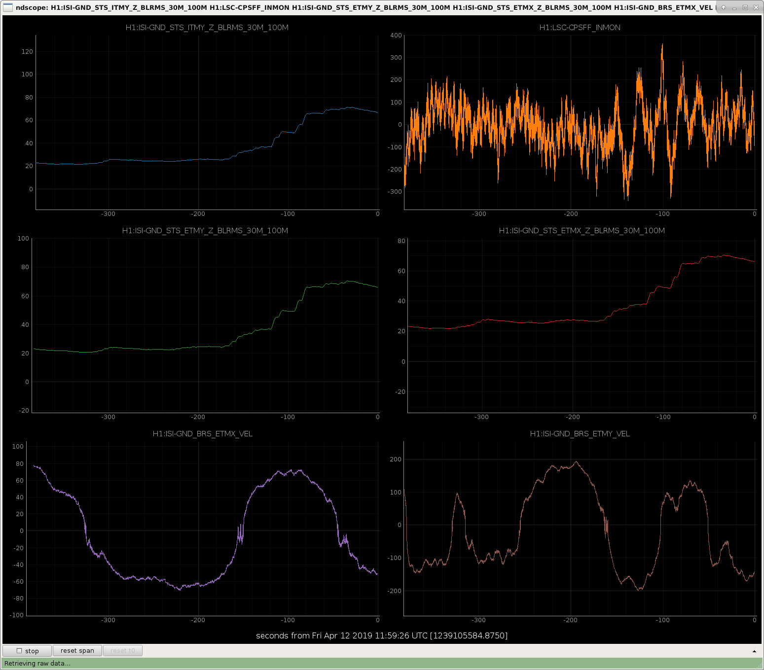
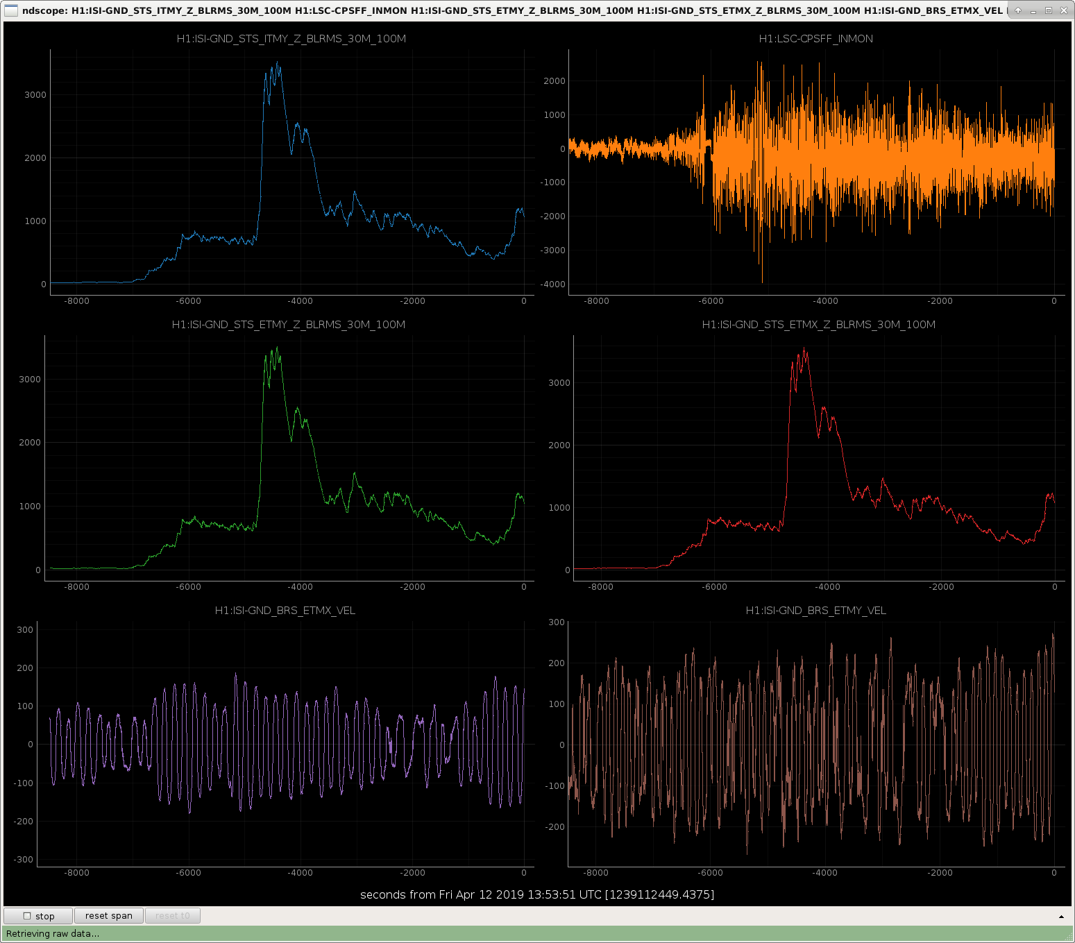
still locked, ground motion taking off now
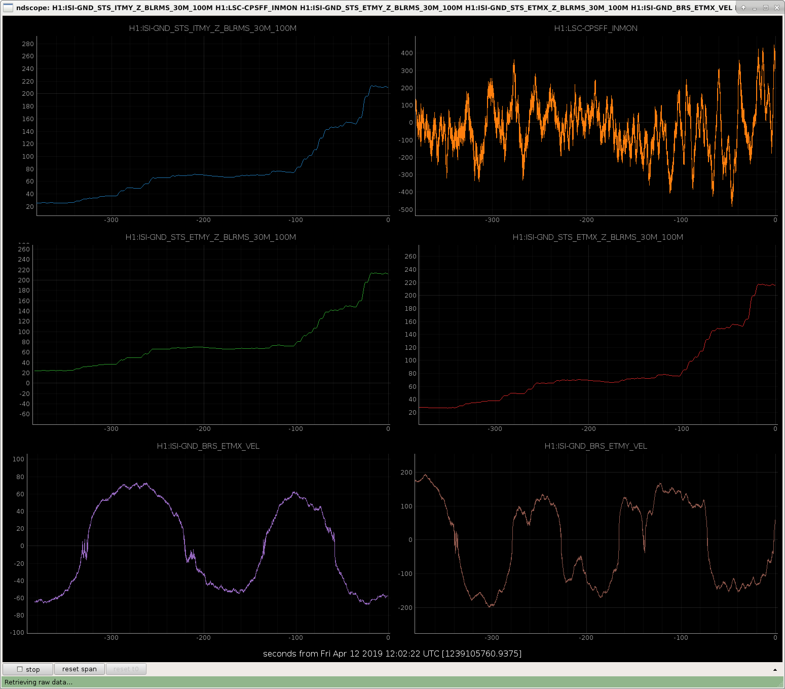
broke lock a few seconds before this snapshot - SEI now in LARGE_EQ_NOBRSXY.
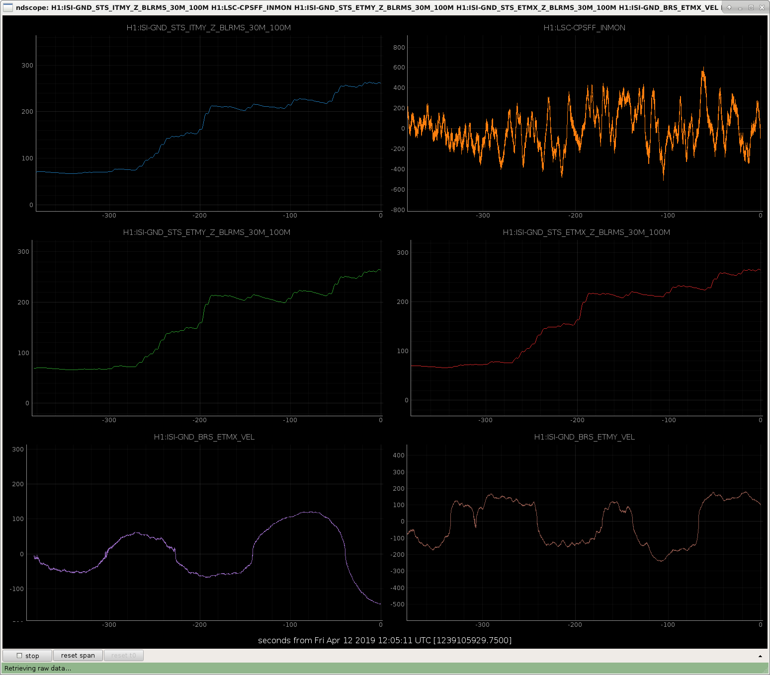
IMC is locked, nothing is tripped
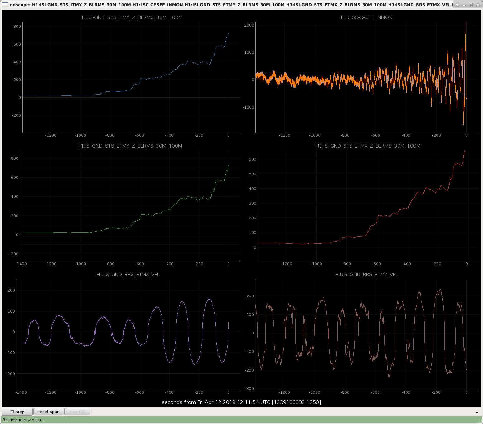
another uptick in ground motion
TITLE: 04/12 Owl Shift: 07:00-15:00 UTC (00:00-08:00 PST), all times posted in UTC
STATE of H1: Observing at 107Mpc
OUTGOING OPERATOR: TJ
CURRENT ENVIRONMENT:
Wind: 6mph Gusts, 5mph 5min avg
Primary useism: 0.02 μm/s
Secondary useism: 0.21 μm/s
QUICK SUMMARY:
H1:ASC-X_PWR_CIRC_OUTPUT AND H1:ASC-Y_PWR_CIRC_OUTPUT limits on video4's lower screen StripTool caused both signals to go out of view at the top of the window.
The original max. values where X:160, Y:170, and the signals are running around X:165, Y:178. In order to have both signals in view as H1 relocks, I set both channel's max. values to 180, and saved the file.
TITLE: 04/12 Eve Shift: 23:00-07:00 UTC (16:00-00:00 PST), all times posted in UTC
STATE of H1: Observing at 107Mpc
INCOMING OPERATOR: Cheryl
SHIFT SUMMARY:One lock loss from unknown causes. Getting ALSY to get anything better than a TEM10 mode was difficult, but got it eventually.
LOG:
Bubba is aware of tonight's H2O RO alarm, I've bypassed its cell phone alarms overnight.
Bypass will expire:
Fri Apr 12 09:02:57 PDT 2019
For channel(s):
H0:FMC-CS_WS_RO_ALARM
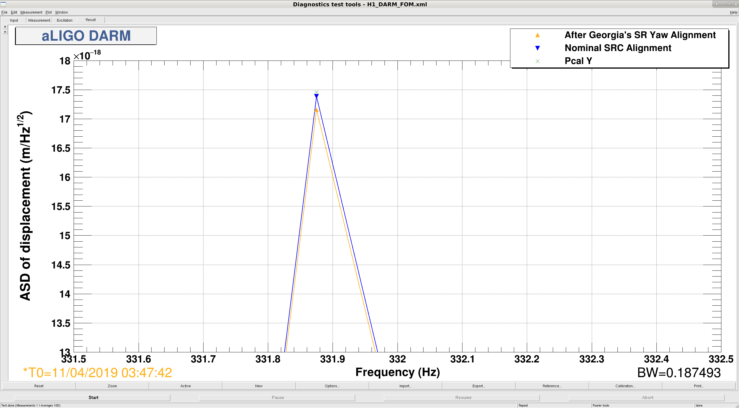
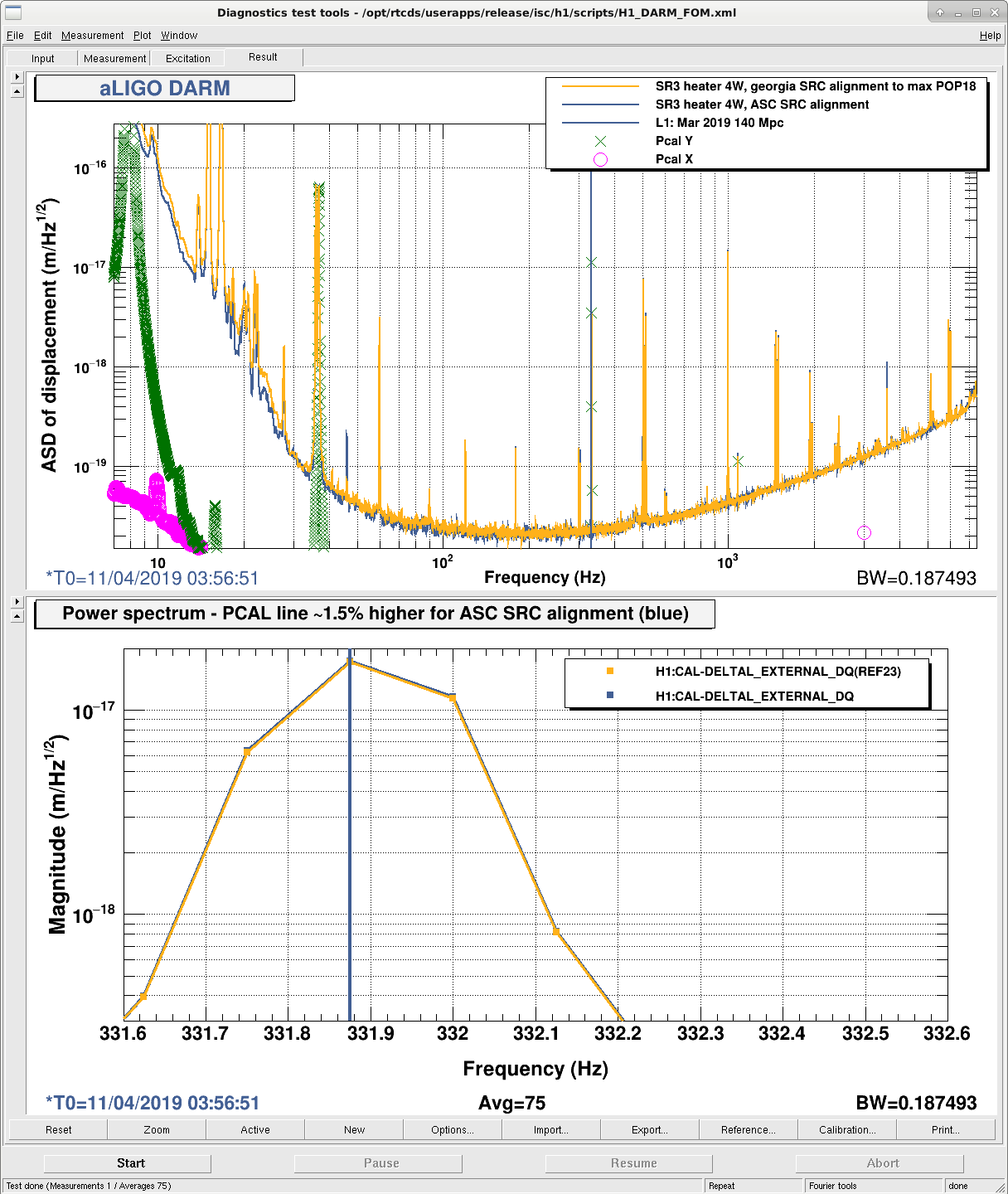
Last night we moved the SR3 heater, and while doing this we found that kappa C (which is supposed to be proportional to DARM optical gain) went the opposite way of the range. In particular, when Georgia moved the SRC alignment in yaw, we saw kappa C increase by about 1%. This made us think we were winning with DARM response. However, when we looked at the DARM spectrum we found that the response to the 331.7 Hz PCAL line had gone down. Since the PCAL line signal had not changed, this means that the DARM optical gain actually decreased. This means that kappa C is going like inverse DARM optical gain. According to documentation (T1700106), kappa C ought to be proportional to optical gain.
Lili, Danny, Sheila
Last night we looked through the front end calculation of this one step at a time, and indeed the front end does estimate that the DARM response to PCAL at 331Hz is increasing at this time. Lili has now convinced Danny and I that this is all right, that the reported change in cavity pole frequency and kappa_c are together correctly explaining the change in the magnitude of the sensing function as measured by the 331Hz line.
Ignoring the optical spring, the expression for the (normalized) time dependent part of the sensing function is kappa_c/(1+if/f_c), which I think is what the quantity called S1 in the front end is representing. The magnitude of S1 increased from 0.765 to 0.775 from 2019/04/11 03:48:47 UTC to 2019/04/11 04:07:59 UTC during the SRC alignment test show in the attached screenshot (48406) This is pretty well explained by plugging the reported cavity pole increase from 377 to 407 Hz and the decrease in kappa_c from 1.02 to 1, this would result in an increase in the magnitude of the sensing function at 331Hz even though it is a decrease in kappa_c.
We were out of observing for noise budget injections from 19 UTC until 23:10 UTC. We used 4 hours of commissioning time for this.
We lost lock right away when I accidentally made an injection while ADS was on. 1239044614 We got all the standard noise budget injections we make, with a couple of additions to the normal set: LSC, ASC (added INP1 and updated some of the injections for DC centering loops), jitter, intensity, and two frequency injections to cover the down conversion of frequency noise around the OMC dither lines and normal frequency noise coupling.
Also during this time, I increased the gain of the ADS YAW5 (ITMY spot position to PRM) loop by 10dB, since this was fine I have put it into the ISC lock guardian.
I have also loaded the squeezer guardian, yesterday I compared our code to LLO and changed the names and numbers of some states so that we would be more parallel to their names and numbers. The old and new mappings are in the attached text file.
TITLE: 04/11 Eve Shift: 23:00-07:00 UTC (16:00-00:00 PST), all times posted in UTC
STATE of H1: Commissioning
OUTGOING OPERATOR: Travis
CURRENT ENVIRONMENT:
Wind: 10mph Gusts, 8mph 5min avg
Primary useism: 0.06 μm/s
Secondary useism: 0.19 μm/s
QUICK SUMMARY: Commissioners are finished up and we will be heading back into observing shortly.
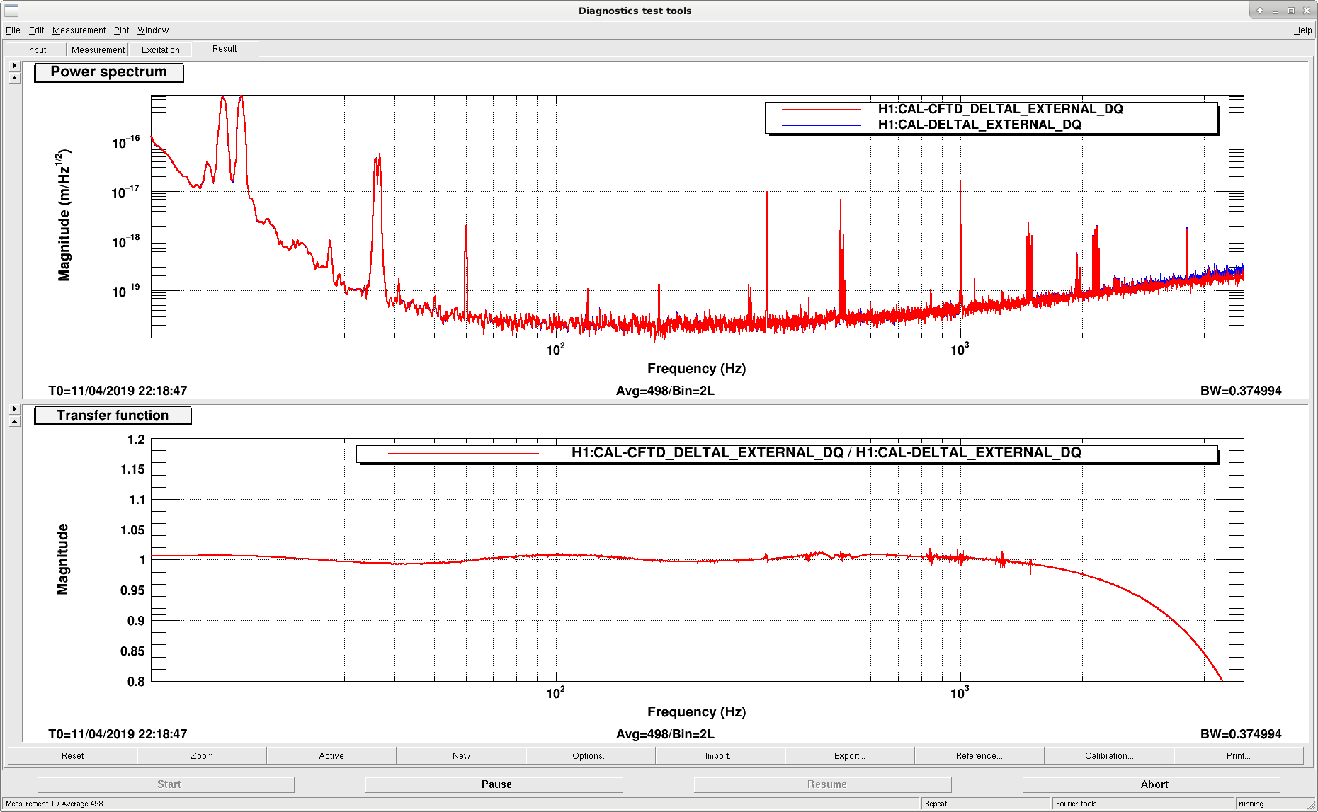
After all the latest model and fitting work by JeffK and Lilli, Jeff installed the appropriate inverse sensing filter (same as for 'usual' darm, but doesn't have the cavity pole in it, and also doesn't have some high freq stuff, since those get take care of in series just after the filter).
I had been confused at that time, and wondered why the CFTD inverse sensing filter bank also had a whitening filter in it, so Jeff turned it off. After further looking around today, I discovered that really it's just that the CFTD path does the whitening in a different place than in the 'usual' path for some numerical precision reasons, so we really did need that whitening filter on. So, with the updated inverse sensing filter, and the whitening filter correctly on now, and also the integer number of delay cycles set to 9 to match the 'usual' DARM path, the CFTD version of DARM seems to be ready for use.
It looks like there is some discrepancy at high frequencies that I don't yet understand, but otherwise I think we can use the CFTD version for references when we are doing tests.
The high frequency issue is also seen at L1 and has to do with the way the the EPICS control zpk filter has been coded and differs from a FOTON IIR filter. See documentation from Joe's implementation here: https://dcc.ligo.org/LIGO-G1801581
[Sheila, Jenne]
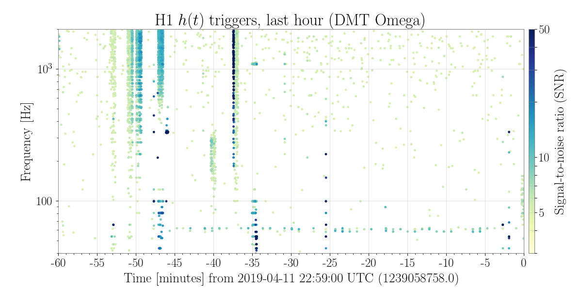
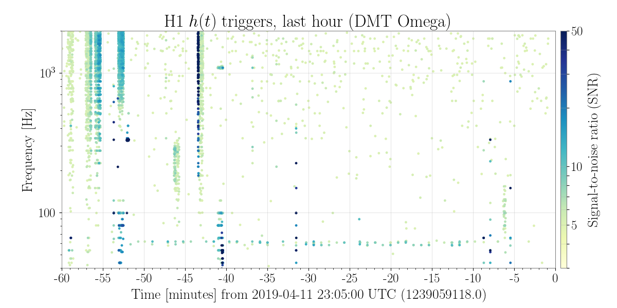
Usually when we are doing calibration-type measurements, we go to our NLN_CAL_MEAS state, which turns off the calibration lines as well as the ADS lines and loops. Sheila had noted in the past that when we go to this state, our 60 Hz glitches seem to go away. That was again true today.
I wanted to look at some calibration things while Sheila was doing her measurements, so I took us back to NomLowNoise (which turned all the lines back on) then I hand-turned off the ADS lines and loops. With this situation (cal lines on, ADS lines off) we see our little train of 60Hz glitches. We don't know right now which line is causing them, but this does narrow it down to being related to the cal lines.
In the attached figure, I turned the cal lines back on around -14 min, and you can see the 60Hz glitches present after that time.
22:40 UTC, turned off PCalX line at 2.5kHz, to see what the 60Hz glitches do. Note that we are still in commissioning mode for scheduled noise budget injections.
With just PcalX off, the glitches are still present. At 22:57 I turned off the PcalY lines.
23:05, turning both PcalX and PcalY lines back on.
With all of the PcalY lines off, the glitches seem to be gone. So, I think this exonerates the suspension calibration lines, and we could in the future try to determine if it is any one specific PcalY line, and decide what to do about it.
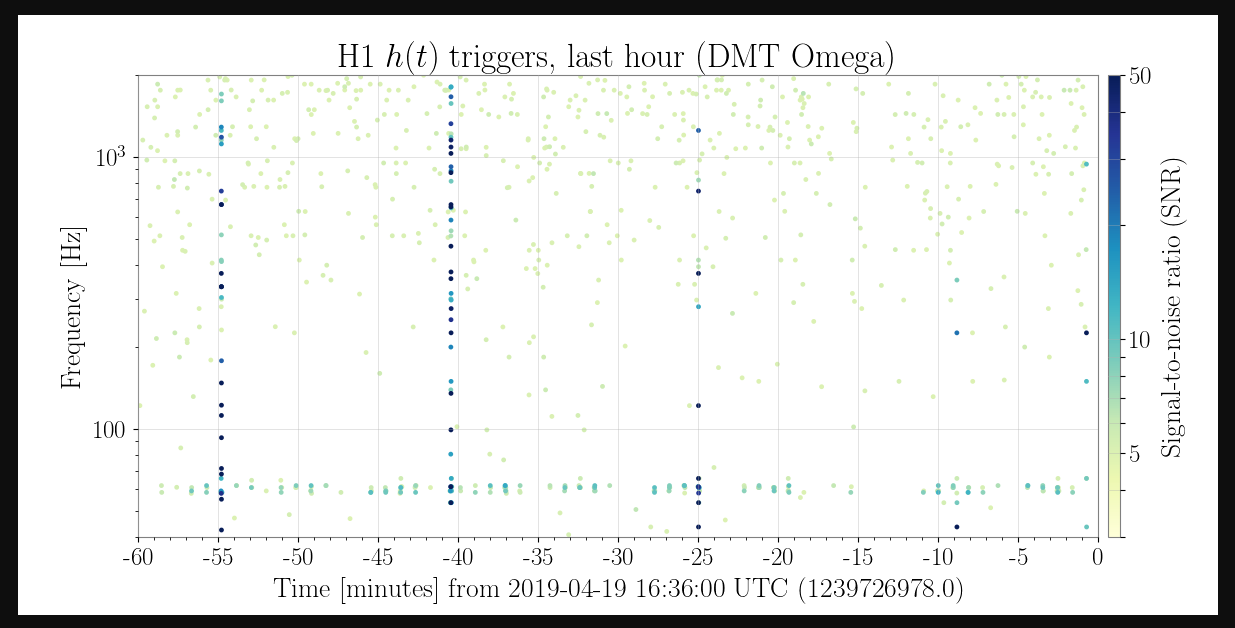
While Jeff B took us out of observing to deal with a violin mode quickly, Jenne and I turned off the excitation for the 7.93 Hz pcal Y line for 4 minutes from 16:21:20 to 16:25:30 UTC April 19th. The glitches around 60Hz seemed to be gone when this was off.
Also, to note, moving the frequencies of lines 1+2 48551 doesn't seem to have had much of an impact on these glitches, you can compare dmt omega plots from the summary pages before and after the change.
Craig, Danny, Georgia
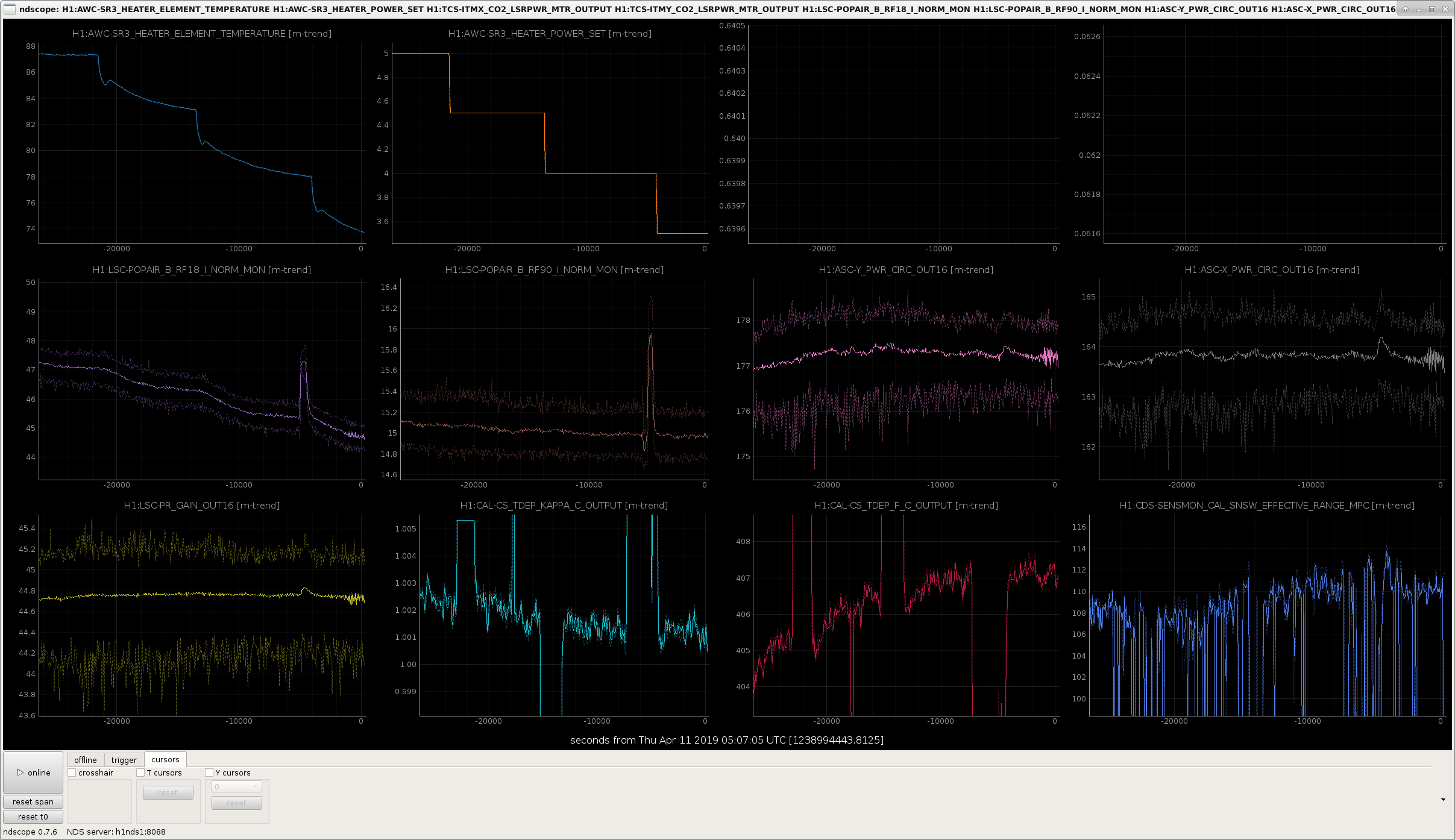
Today we stepped the SR3 heater down in 0.5 W steps, from 5W to 3.5W, according to plan. Here's what we found as we reduced the heating on SR3:
These values are shown in the first attachment, The kick in many signals just before we stepped down to 3.5 W is explained below.
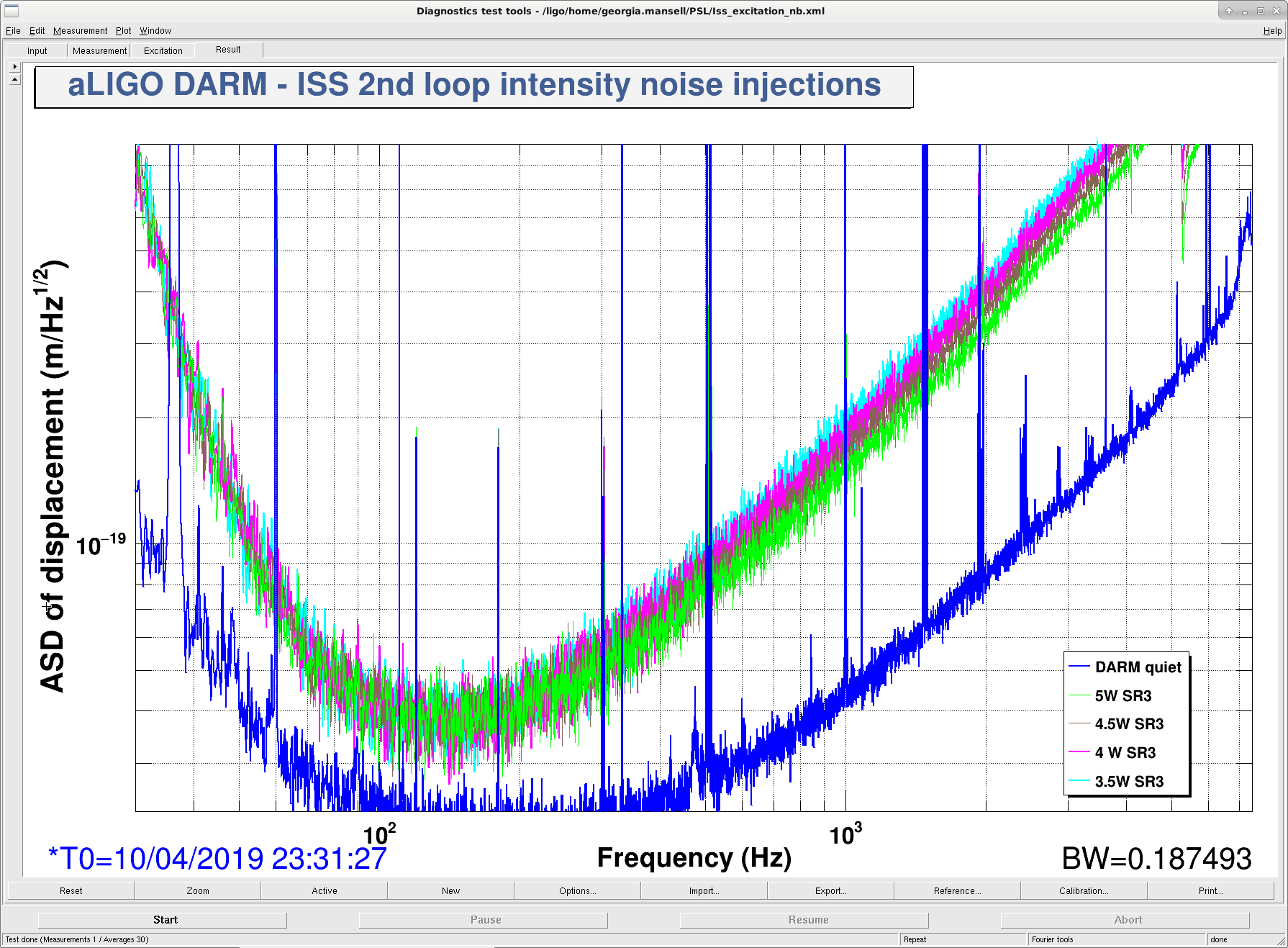
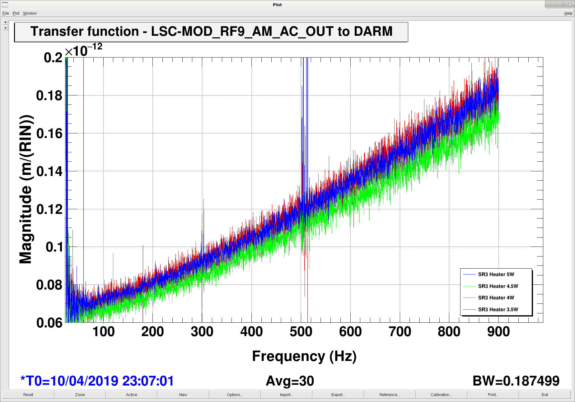
We also monitored the DARM plant, frequency noise coupling, intensity noise coupling, and RF9 RIN coupling at each step.
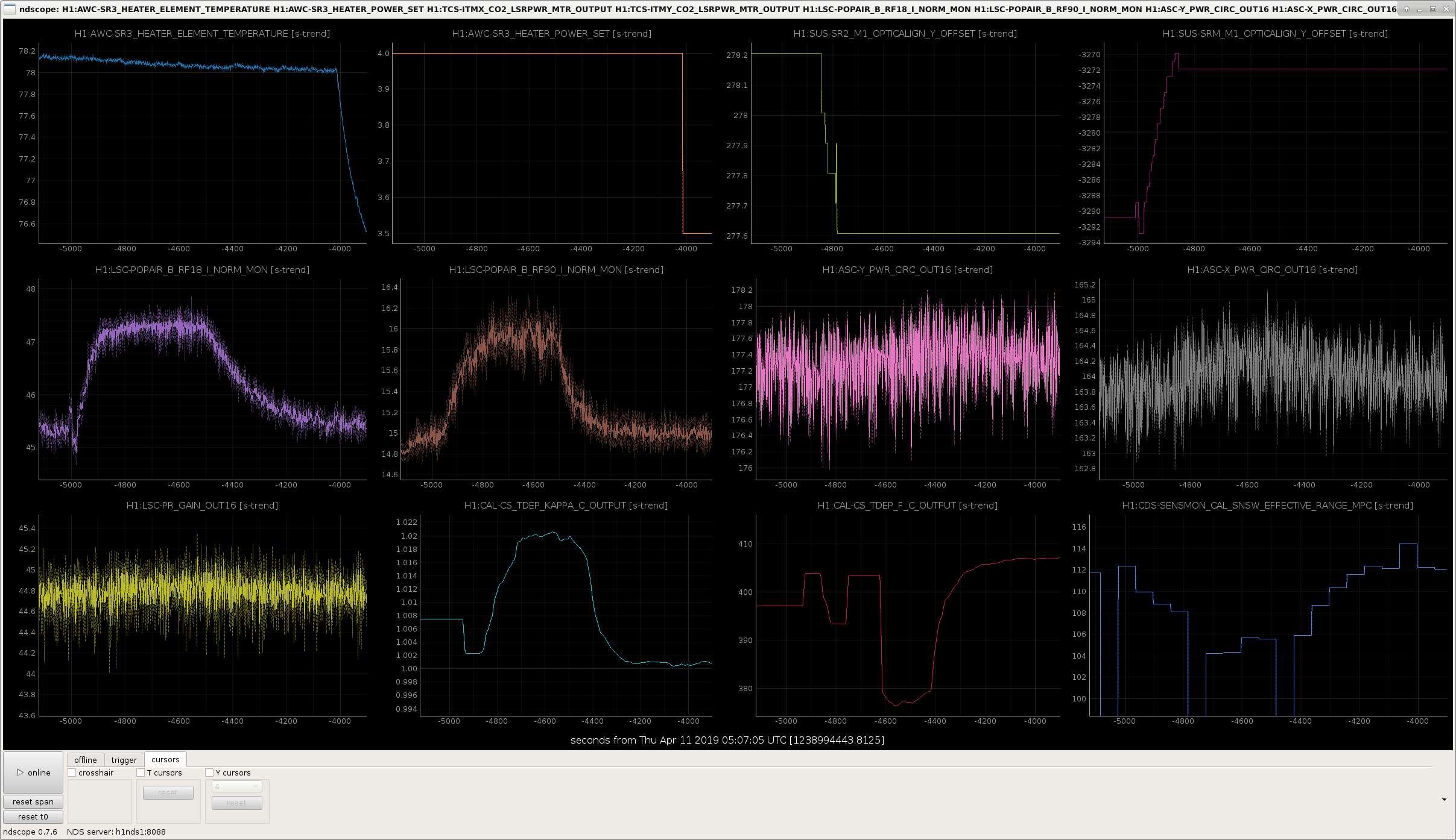
While we were sitting at 4W on the SR3 heater we checked for detuning in the SRC ASC. This is the big peak in RF18 and RF90 in the first attachment; the 4th attachment is zoomed in during this time. We opened the loops and moved the sliders (top right plots), found nothing too interesting in pitch, but while aligning yaw we saw:
We were surprised that the optical gain increased, that doesn't seem to hang together with the other pieces of information here. Maybe we should consider operating with 4W on the SR3 heater, and re-phasing the SRC ASC for this. [Edit: notes for attachment 4: at t = -4500s we turned the SRC ASC back on, which is why the alignment went back to its nominal level. The calibration lines were off before t = -4800s, and the calibration values before this time are not to be trusted.)
We now understand that the increasing Kappa_C corresponded to a decrease in optical gain. So we were misaligning the SRC when we were aligning it by hand. The fact that RF18 was able to be improved with a misaligned SRC suggests there's room for improvement in the beamsplitter or PRC alignment.
We have made some DARM spectra from times during our SR3 heater test, and SRC alignment test.
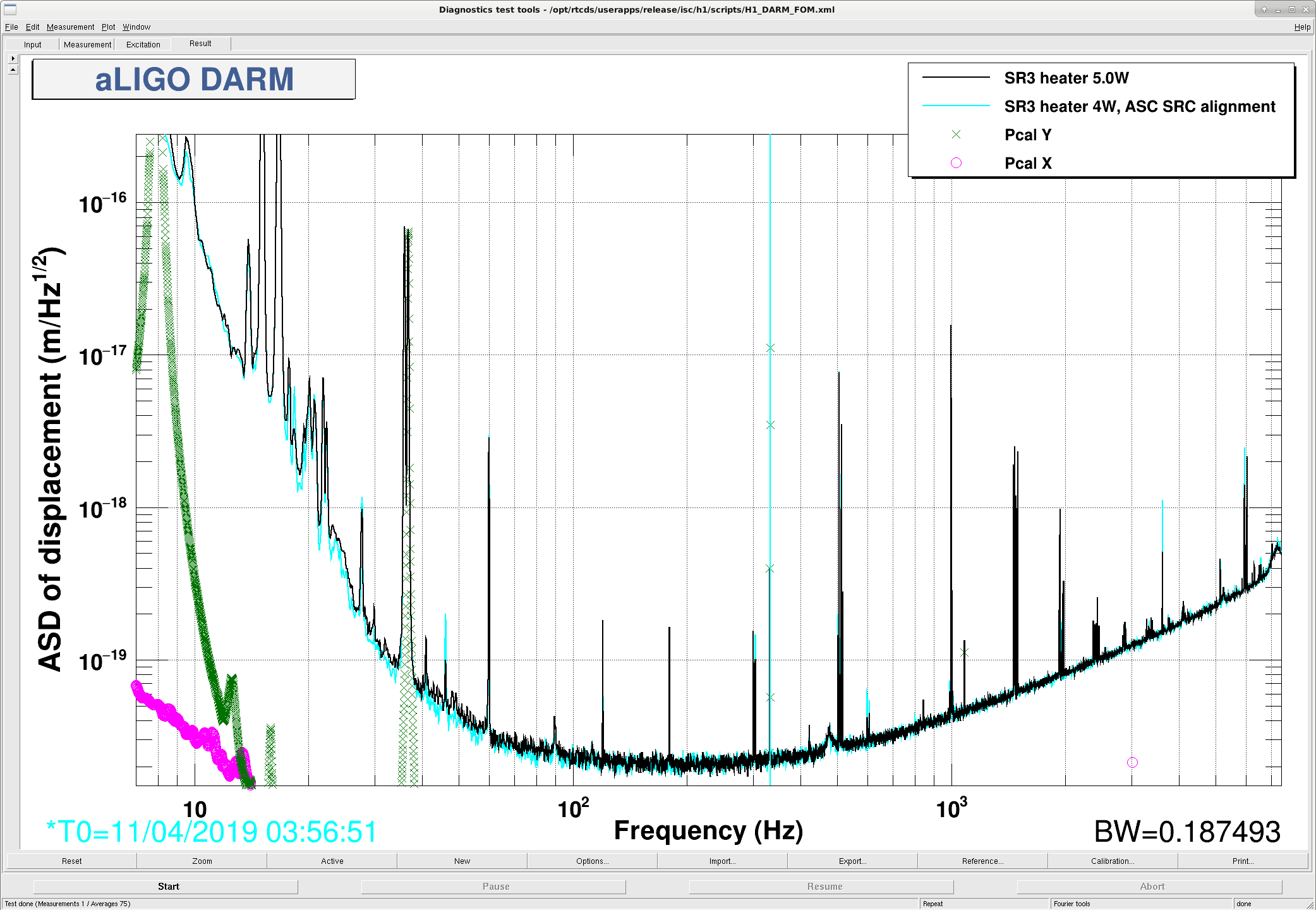
First attachment shows DARM with the SR3 heater at 5W (black) compared to 4W (cyan), showing definite improvement in the bucket, which explains our range increase. A similar spectrum at 3.5 W on the SR3 heater sits somewhere in between these two.
Second attachment shows DARM with SR3 heater at 4W, with the normal alignment (blue), and when we opened the SRC ASC loops and "aligned" by hand, maximising POPAIR_B_RF18 (yellow). It seems like I can undo the SR3 heater improvement by misaligning the SRC...
The DARM plant did not change very much over the period of the SR3 heater move.
I measured the DARM plant 4 times, at SR3 power of 5W, 4.5W, 4W, and 3.5W. The DARM plant did not change very much this time.
According to some MCMC fits:
Optical Gain = 3.20 +- .28 × 106 cts/m (<0.8 % uncertainty)
DARM pole = 417.80 +- 15 Hz (4 % uncertainty)
Delay = 5.31 +- 1.7 × 10⁻⁵ s (33 % uncertainty)
Spring Freq = -5.12 +- 1.6 Hz (32 % uncertainty)
Spring Q = 37.11 +- 4.7 (13 % uncertainty)
This is a different result than the SR3 heater move at 30W input power. We moved the SR3 heater by less this time (from 5W to 3.5W rather than from 0 to 5 W before). We would also like to test the DARM plant for SRCL offset and DARM offset changes.
Also the frequency noise coupling to DARM did not change. Will post plots later once they are correct.
Posted DARM ASDs, calibrated frequency ASDs, and frequency coupling TF plots. DARM calibration: 6 zeros at 30 Hz, 6 poles at 0.3 Hz, gain of 1 Frequency Calibrations: Same as 46864. See attached freqCals.txt. Comparison to 30 W coupling: 45831. Before, we had a dip in the freq-to-DARM coupling at around 30 Hz where the radiation pressure and contrast defect effects destructively interfered. Now that effect seems to have flattened out. (Plot 3 in the PDF) Over the SR3 heater test cooling from 5W to 3.5W, it seems our freq-to-DARM coupling increases by a few percent, but does not change too radically.
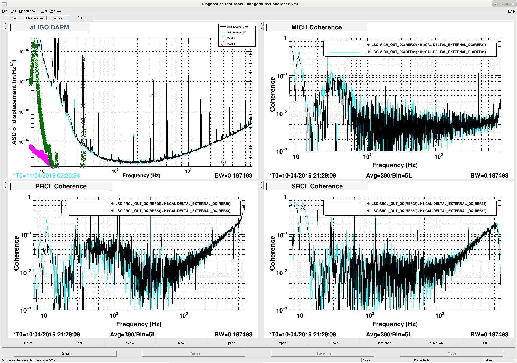
Sheila was thinking the SR3 heater improvement could be attributed to the changing MICH and SRCL feed forward. I had a look at the coherence between DARM and MICH/PRCL/SRCL during the SR3 heater test, comparing a time at 5W (black) and a time at 4W (cyan), and am not convinced the coupling changed significantly. If anything the MICH coherence is worse at 4W than 5W in our frequency band of interest (20-60 Hz).
Unfortunately a pair of h1edc CRC errors this afternoon at 14:48:49 PDT.