Displaying reports 42881-42900 of 88649.Go to page Start 2141 2142 2143 2144 2145 2146 2147 2148 2149 End
Reports until 20:31, Wednesday 27 February 2019
H1 AOS
jenne.driggers@LIGO.ORG - posted 20:31, Wednesday 27 February 2019 - last comment - 21:26, Wednesday 27 February 2019(47170)
Circulating powers seem rattier now vs. old spots, but there isn't more angular motion

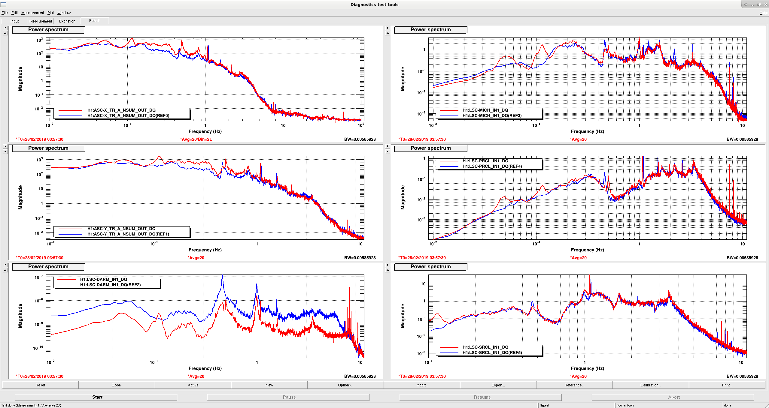
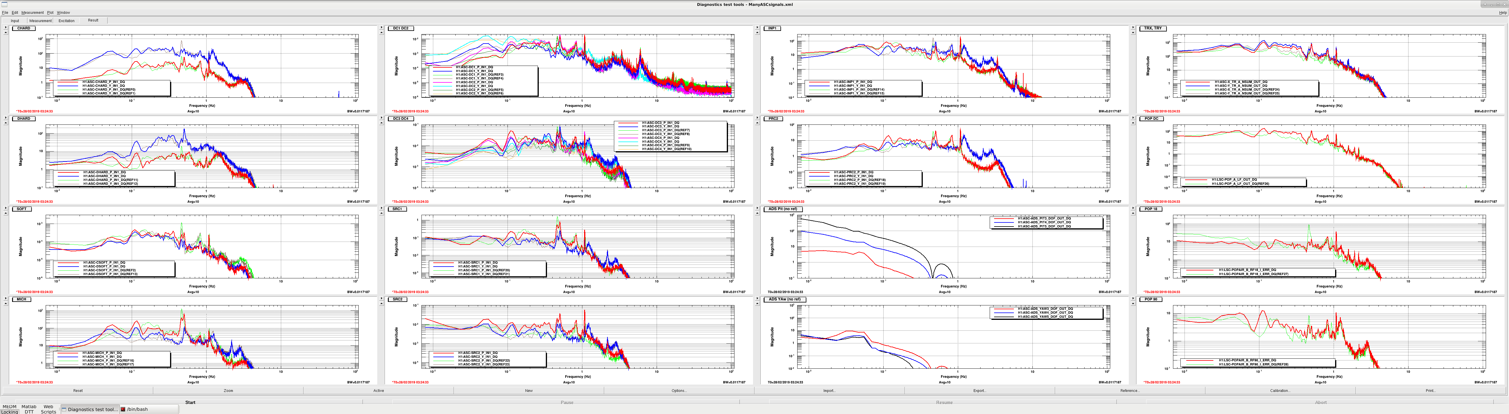
With the new spot positions that we're using to avoid hitting too strongly on the ITMY point absorber, we seem to see that the circulating powers on our time series plots look a bit noisier than they used to.  Attached is a plot where the references are from the 'improved spectrum' alog time (47011) which was with the old spots, and the 'live' traces are from this evening, with the new spot positions and higher circulating powers. None of these traces are calibrated, sorry.

The angular traces (left 3 columns) don't really see a lot more noise than the references, and in some cases seem to see a bit less (I'm not taking ground motion into account here).  The exceptions are SRC2 (2nd column, bottom row), and PRC2 (3rd column, 2nd row).  However, the powers (right hand column) shows a fair amount more motion.  We may need to tighten our SRC2 ASC loop, as well as look at some of our length loops to see if they need to be tightened up.

Images attached to this report
Comments related to this report
daniel.brown@LIGO.ORG - 21:26, Wednesday 27 February 2019 (47174)

Looking at the LSC signals for the same time periods, it looks like the new peaks in the circulating power at 0.005, 0.1, 0.5 Hz are from PRCL/MICH.

Images attached to this comment
H1 ISC
stefan.ballmer@LIGO.ORG - posted 20:27, Wednesday 27 February 2019 (47172)
OMC alignment optical gain maximization

Peter, Stefan,

We went through all 4 OMC alignment degrees of freedom, stepping the APD offsets by about 0.1 in either direction. At the same time we monitored the 331.9Hz cal line. In all 8 directions we saw the optical gain.

We still want to try a proper beam-walking optimization - according to the design (T1000276) the QPDs are 31.1deg apart in Gouy phase.


H1 SQZ (SQZ)
rich.abbott@LIGO.ORG - posted 19:56, Wednesday 27 February 2019 (47171)
New 6.25MHz Photodiode for Squeezer CLF
Peter, Luis, Rich

A new RFPD has been built by Luis Sanchez at CIT and is ready for installation once the DC transimpedance is set (see below).  Upon arrival, we retested the unit for any parameter shift that may have happened during shipment.  The measured parameters associated with this detector are:

Device Serial Number S1900052
Center Frequency = 6.25MHz
Resonant circuit Q = 27.65
Input Transimpedance (inferred from Q) = 6.5kohms
Shot Noise Equivalent Photocurrent = 10.5uA

We still need to increase the transimpedance of the DC path on this unit, but doing so will limit the use of the portable laser calibrator as the photocurrent from the calibrator is of order 5mA.  This unit is designed to operate at a photocurrent of approximately 10uA.  The present value of the DC transimpedance stage is the nominal 100ohms, which should be increased to either 10kohms, or perhaps even 100kohms.  There is a differential transmitter after this stage that would add an additional gain of two to the resulting transimpedance.
Non-image files attached to this report
H1 ISC
sheila.dwyer@LIGO.ORG - posted 19:46, Wednesday 27 February 2019 (47164)
DARM boost added in PUM

Sheila, Peter, Danny, Stefan, Jenne

We have been having intermittent locklosses when transitioning DARM from ETMY to ETMX since I made the changes to the UIM filter described in 46861. This looks like a crossover instability between the PUM and ESD at 4.5-5 Hz.  It is interesting that this only seems to happen early in the lock, either in the transition or in the first 15 minutes of the lock, if we get through that then the interferometer can be stable for many hours. 

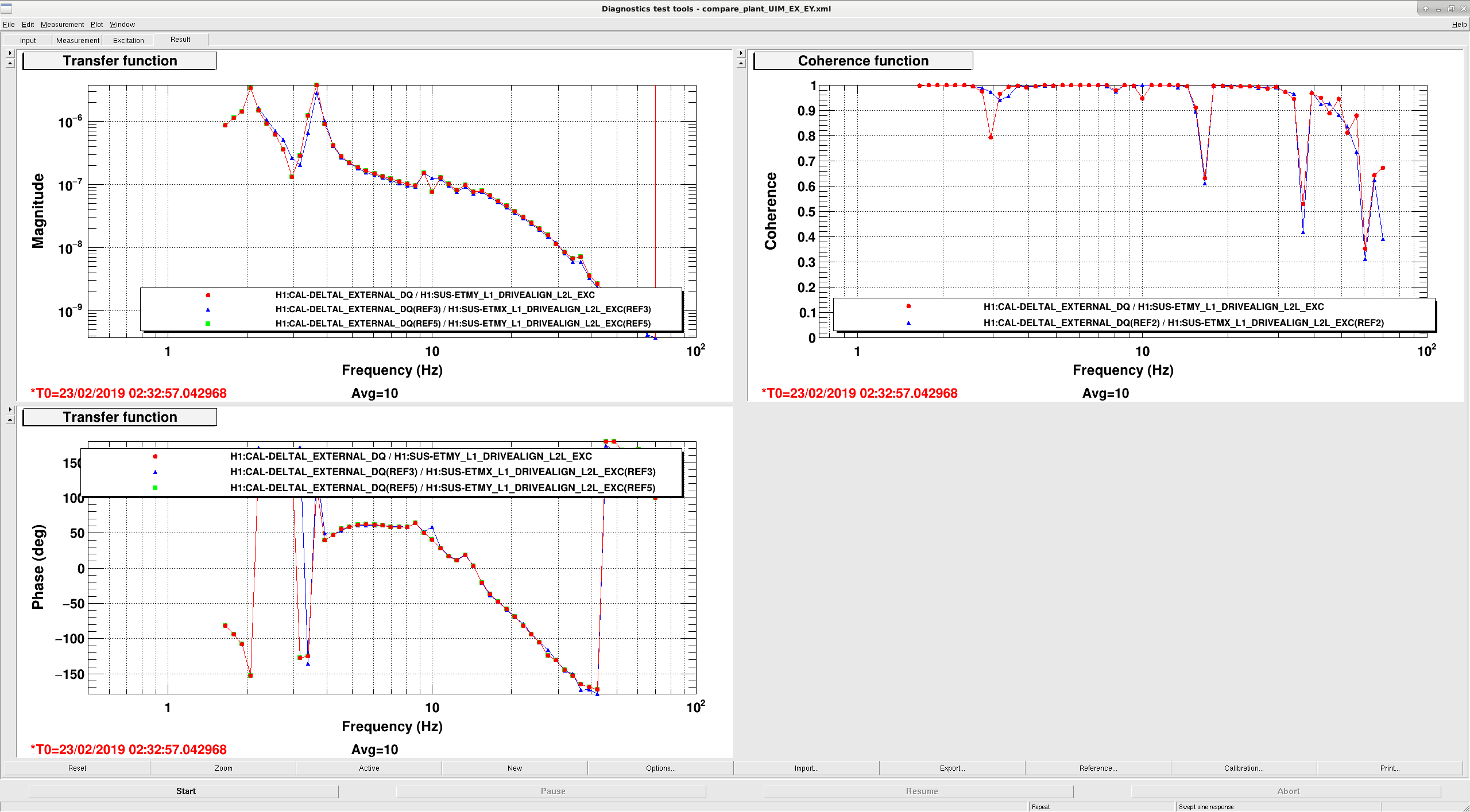
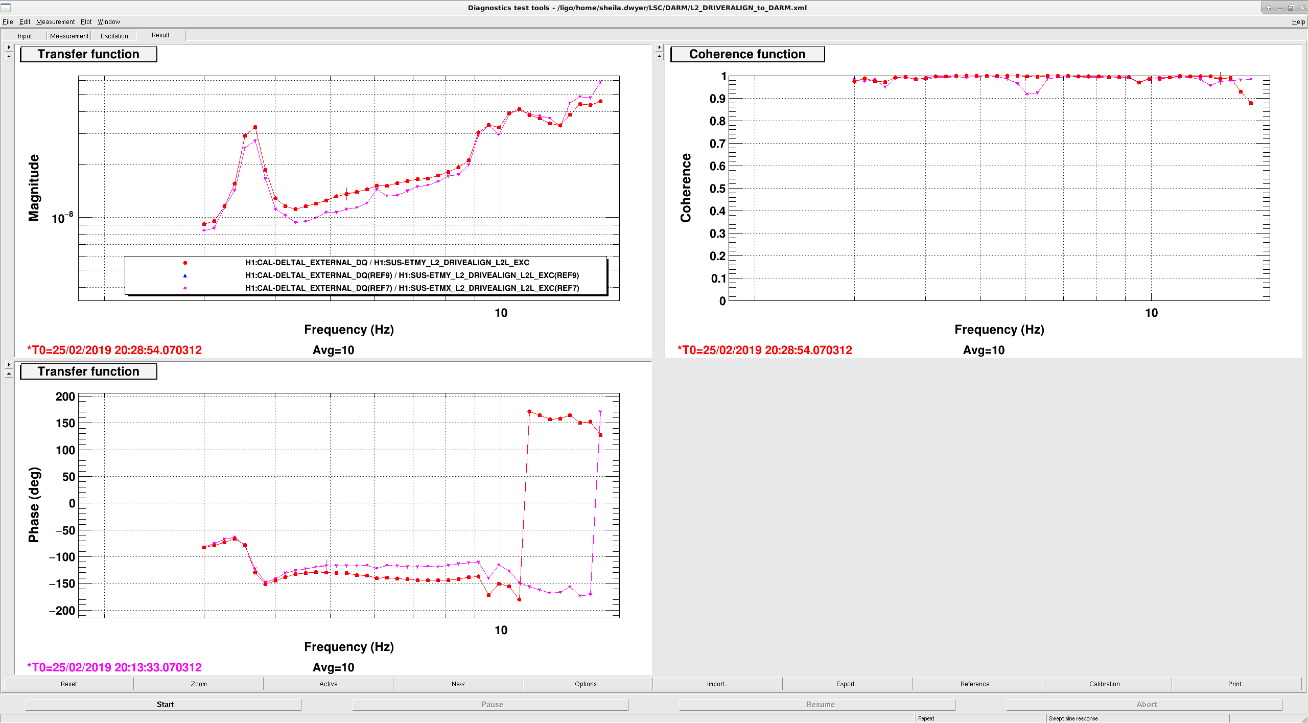
Since we only have this problem when actuating on ETMX, not ETMY, we took some measurements to compare the actuators. The first two attachments show the comparison of an excitation at drivealign to CALDAELTAL without the whitening corrected for.  The EX PUM has 20% more gain at 5 Hz than EY, but nothing in these measurements can account for an instability. 

Yesterday Peter F and I looked at the DARM filters from LLO, at LLO they have a larger relative gain between the PUM and the ESD, we have more boosts in the DARM filter bank here which means that we end up with a shallower cross-over between the PUM and ESD.  We tried (unsucsesfully) to transition DARM to a configuration that would get rid of the low passes and high passes that we have in drive-align and simplify our loop design. 

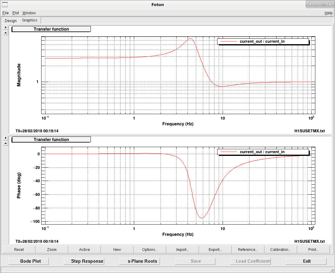
Instead of trying to debug this simpler configuration, we decided to make a small change to the loop which was to add a boost in the PUM lock filter (3rd png attachment shows the filter). The overall loop before and after the change is shown in the first two pdf attachments.

We attempted to measure the PUM crossover after this change, but had difficulty getting  a coherent measurement, even though our excitation was a couple orders of magnitude above the noise in both In1 and In2.  The third attached PDF shows the crossovers before and after this change. 

We also took a Pcal sweep after making this change and updating the actuator model.  It is saved in the usual place. 


Images attached to this report
Non-image files attached to this report
H1 ISC
jenne.driggers@LIGO.ORG - posted 16:53, Wednesday 27 February 2019 (47168)
Green initial alignment references set for new spot positions

I have reset the green initial alignment spot positions, so that initial alignment will bring us back to the place that we explored on Monday that is about 7mm higher on ITMY than we have been, so that we're splitting the difference between 2 different point absorbers on ITMY.  See alog 47117 for the spot exploration.

Still not done is alignment of the ALS beatnotes with this new alignment.

H1 CAL (CAL, ISC, SUS)
jeffrey.kissel@LIGO.ORG - posted 16:46, Wednesday 27 February 2019 (47167)
Updated ETMX L2/PUM and L3/TST/ESD Stage Electronics Compensation (Not L1/UIM)
J. Kissel, J. Driggers

We've used the results from LHO:47166 and 46773 to install improved compensation for the H1 SUS ETMX (L2/PUM) and (L3/TST/ESD) stages, respectively. The new compensation is now ON and running.

Attached are the frequency-dependent systematic error improvements that should be gained by each actuator stage from these installations, assuming we run the PUM driver in State 3 (ACQ OFF, LP ON) and the ESD driver in State 2 (LP ON) during nominal low noise.

In the interest of time and person power, I've elected to *not* improve the compensation for the UIM driver, because
    (a) The frequency band in which the UIM driver is involved in the DARM loop is below the detection band of interest at ~20 Hz and above
    (b) We are only using State 1 of the UIM driver (all LPs OFF), which has a simple zero:pole = (300:85) Hz response is probably good enough.
Non-image files attached to this report
H1 SUS (CAL, ISC)
jeffrey.kissel@LIGO.ORG - posted 16:38, Wednesday 27 February 2019 (47166)
Fits to ETMX PUM Driver Electronics
J. Kissel

I've finally got results for updating the PUM driver compensation filters. Many excruciating details below, 

The final answers, listed in [zeros]:[poles] format,
    (ACQ OFF) SUMMARY (simAcqOFF filters)
        UL = [11.3742] : [117.3675]
        LL = [11.9118] : [115.3799]
        UR = [11.6034] : [119.1647]
        LR = [11.5558] : [119.1031]
     (ACQ ON) SUMMARY (simAcqON filters)
        UL = [1.3262] : [113.6504]
        LL = [1.4191] : [113.8817]
        UR = [1.3412] : [115.0913]
        LR = [1.3421] : [115.1311]
     (LP) SUMMARY (simLP filters)
        UL = [ 5.5323 22.4187] : [0.4979 245.6072]
        LL = [ 5.4697 21.8761] : [0.4915 240.0583]
        UR = [ 5.5514 22.1419] : [0.4988 243.0059]
        LR = [ 5.5456 22.2043] : [0.4989 243.4424]
the updates to the antiAcqOFF, antiAcqON, and antiLP filters are the same, but with the zeros and poles flipped.

And here are the details of how I've arrived at these numbers.
It took a *very* long time to arrive at what data gathering technique to use:
    (1) measuring the driver in analog, fully differential (a la diagram in LHO:24725) >> tried to take data on 2019-01-29 but ran out of time during maintenace
    (2) measuring the driver in analog, single ended (a la diagram in LHO:46927) >> took data on 2019-02-03, results confusing, good enough to fit the LP circuit
    (3) measuring a combination of broad-band and swept sine excitations through the coil driver monitor circuits (a la diagram in LHO:21232) >> took data on 2019-02-07, results confusing/ not good enough
    (4) measuring only broad-band excitations through the coil driver with very well-tuned drives (same as above) >>  good enough to finally fit the ACQ circuits.

The well-tuned templates for (4) live here:
    /ligo/svncommon/CalSVN/aligocalibration/trunk/Common/Electronics/H1/Data/SUSElectronics/ETMX/PUM/2019-02-26/
        2019-02-26_H1SUSETMX_PUMDriver_WhiteNoise_0p05to5Hz_State1_TF.xml
        2019-02-26_H1SUSETMX_PUMDriver_WhiteNoise_0p05to5Hz_State2_TF.xml
        2019-02-26_H1SUSETMX_PUMDriver_WhiteNoise_0p05to5Hz_State3_TF.xml
        2019-02-26_H1SUSETMX_PUMDriver_WhiteNoise_0p05to5Hz_State4_TF.xml
        2019-02-26_H1SUSETMX_PUMDriver_WhiteNoise_0p1to7000Hz_State1_TF.xml
        2019-02-26_H1SUSETMX_PUMDriver_WhiteNoise_0p1to7000Hz_State2_TF.xml
        2019-02-26_H1SUSETMX_PUMDriver_WhiteNoise_0p1to7000Hz_State3_TF.xml
        2019-02-26_H1SUSETMX_PUMDriver_WhiteNoise_0p1to7000Hz_State4_TF.xml

You can find all of 
- the explanations and demonstration of how the data from (2) and (3) were bad, and 
- how I arrived at these poles and zeros by plugging ratios of states into IIRrational V2
in a presentation I gave the CAL group today, G1900321, but for brevity, I'll not repeat the saga here.

However, the final data was processed using
    /ligo/svncommon/CalSVN/aligocalibration/trunk/Common/Electronics/H1/Scripts/
        model_ETMX_PUM_driver_20190226.m
which produced (a) plots showing all of the steps in the data conditioning, and (b) plots which helped aide the choice about which data I used for fitting,

and fit the data using
    /ligo/svncommon/CalSVN/aligocalibration/trunk/Common/Electronics/H1/Scripts
        fit_ETMX_PUM_driver_20190226.py

The resulting cleaned data sets are saved to text files (for future IIRrational use-case testing) here:
    /ligo/svncommon/CalSVN/aligocalibration/trunk/Common/Electronics/H1/Results/SUSElectronics/ETMX/PUM/2019-02-26
        2019-02-26_H1SUSETMX_PUM_Driver_${FilterStage}_${Coil}_tf.txt
where ${FilterStage} = [LP, ACQOFF, ACQON], and ${Coil} = [UL, LL, UR, LR].

All plots are all in the same directory, but I attach the highlights here.
2019-02-26_H1SUSETMX_PUM_Driver_summary.pdf Summary of data conditioning.
    - pgs 1-16 show the import of the data, and how the two frequency ranges of broadband injections are combined, and filtered for *very* high coherence (coh > 0.998!)
    - pgs 17-32 show the comparison of coil driver monitor circuit measurement (4) results (called "DTT"), compared against the analog measurement (2) results (called "SR785").
    - pgs 33-44 show the ratios of transfer functions that were used in the fitting routine (SR785 data for the LP stage, and DTT for the ACQ stages)
2019-02-26_H1SUSETMX_PUM_Driver_${FilterStage}_FitResults.pdf
    - Shows the result of the fitting algorithm for each filter stage and coil.
2019-02-26_H1SUSETMX_PUM_Driver_State3_FitvsModel_TFImpact.pdf
    - Shows the expected change in the PUM stage's longitudinal drive response as a result of these changes. This shows that the impact is (of course, frequency dependent, but at worst) at the 5% / ~few deg level.

Conclusions after all this work (repeated from the end of G1900321):
- Use coil driver monitor path measurement technique. It’s “less” confusing (though still confusing), much quicker, and contains everything we need.
- Analog measurements expose the impedance of the OSEM, so they’re interesting, but one *cannot* use single-ended drive (without further exploration) and must be careful not to saturate the circuit, lest you get even more confusing results.
- Use ratios of transfer functions to simplify what work the fitting routines need to do.
- I've been able to use the newest fitting program on the block – IIRrational (see Documentation, but it didn’t come with out several hours talking to the author of the code), and it’s python friendly (though data processing is still easiest in matlab).
- We need to get residual between data and fit below 1% and 1 deg, and we’ve achieved it.
- When compensation is updated, will claw back ~5% / few deg in systematic error.

    
Non-image files attached to this report
LHO General
thomas.shaffer@LIGO.ORG - posted 16:00, Wednesday 27 February 2019 (47165)
Ops Day Shift Summary

TITLE: 02/27 Day Shift: 16:00-00:00 UTC (08:00-16:00 PST), all times posted in UTC
STATE of H1: Commissioning
INCOMING OPERATOR: None
SHIFT SUMMARY: After the Comm beatnote issue was resolved, we were able to get to low noise once, but then we have struggled at the DHARD_WFS state.
LOG:

1300 Peter K to PSL
1657 Rich A, Jenne, Fil to LVEA near HAM6 to check on ground loop
1744 Rich A, Jenne, Fil out
2106 Betsy, Rick to Opt Lab

H1 ISC (ISC)
rich.abbott@LIGO.ORG - posted 13:18, Wednesday 27 February 2019 (47161)
OMC Grounding Issues Revisited
Jenne, Kara, Stefan, Keita, Peter, Shiela, Rich

Results summary:  With the 3 OMC cables removed from their respective rack mounted chassis (QPD, DCPD, PZT), there are no connections between any two cable shields, and none of the shields are connected to chamber ground.  This agrees with the wiring diagrams so far.

As relates to the OMC Air-to-Vacuum cabling, it is established that the QPD cable shield is tied to rack ground when the DCPD cable is plugged into the split whitening via the squeezer 3.125mHz pickoff chassis.  There must be some connection between the QPD shield and a "Ground" wire in the DCPD wiring chain. Remember, the QPD shield is NOT connected to the DCPD shield, NOR is it connected to the PZT shield as verified by direct measurement.

Attached is a new revised cartoon plan that shows the results of the initial measurements, and plans for a new set of measurements to get to the (next) bottom of this matter.  

What is not clear is how the QPD shield gets grounded by plugging in the DCPD cable to its rack mounted chassis.
Non-image files attached to this report
LHO General
thomas.shaffer@LIGO.ORG - posted 11:33, Wednesday 27 February 2019 (47159)
Ops Mid Shift Report

From Peter King's alignment work this morning, the Comm beatnote has been improved to -3dB. The beatnote is nominally around +5dB, but yesterday we could only get it to -14dB. We have been able to lock with the beatnote at -6dB in the past, so we believe this should be enough to continue locking and commissioning today.

H1 PSL (PSL)
peter.king@LIGO.ORG - posted 10:47, Wednesday 27 February 2019 - last comment - 14:48, Thursday 28 February 2019(47158)
FSS work
This morning I decided to clean slate the alignment of the AOM.

    Measured 145 mW incident on the AOM.  111 mW in the first order; thus a diffraction efficiency
of 76%.  Not great but passable, should be closer to 80-85%.

    Measured 83 mW in the double pass beam headed towards the reference cavity.  This is 57%,
which is close to the expected value of 59%.

    Aligned beam towards reference cavity.  With the transmission photodiode signal at 4.1 V, this
was measured to be 24 mW at the input to the ALS fibre.

    Measured the transfer function and found the UGF to be ~24 kHz, in a repetition from yesterday.
I wiggled the LO and PD SMA cables at the TTFSS end, no effect.  The PD SMA cable at the PD end;
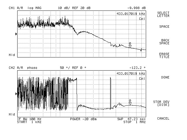
no effect.  Wiggling the SMA cable to the 21.5 MHz EOM instantly restored the UGF to 433 kHz
(CG = 20, FG = 18, see C20F18.jpg).  So either there's a problem with the 21.5 MHz EOM or the cable
going to it.

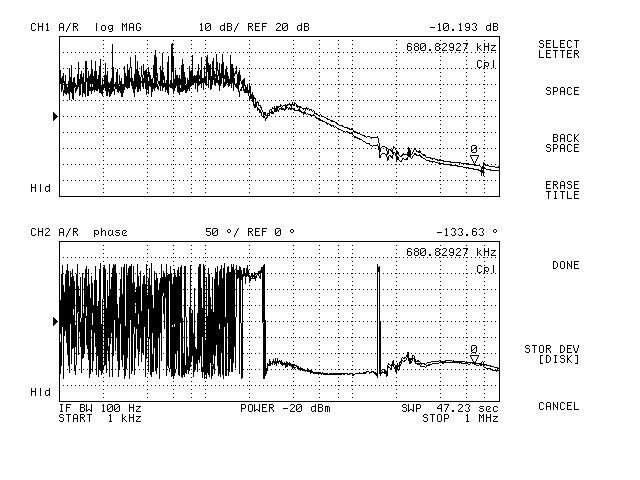
    I left the FSS with CG = 23, FG = 18 (see C23F18.jpg, C23F18.txt for data).  We could probably
dial the common gain back a little.
Images attached to this report
Non-image files attached to this report
Comments related to this report
craig.cahillane@LIGO.ORG - 18:11, Wednesday 27 February 2019 (47169)
IMC gain is back up
Non-image files attached to this comment
keita.kawabe@LIGO.ORG - 14:48, Thursday 28 February 2019 (47198)

Good that the problem was solved.

There was some speculation that the problem came from accidentally catching a single-path AOM beam (alog 47147), but judging from the SQZ and ALS lasers' temperature feedback it doesn't seem to be the case. In the attached, the original jump of frequency was at around -20000 sec, the fix came at around -11000 sec. Frequencies moved in the same direction in SQZ and ALS lasers for both of the instances.

Images attached to this comment
H1 ISC
gabriele.vajente@LIGO.ORG - posted 10:01, Wednesday 27 February 2019 - last comment - 14:16, Tuesday 05 March 2019(47157)
Simulation of point absorber effect - update

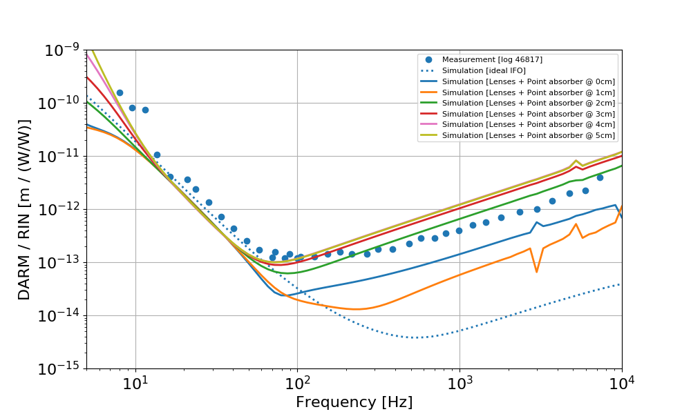
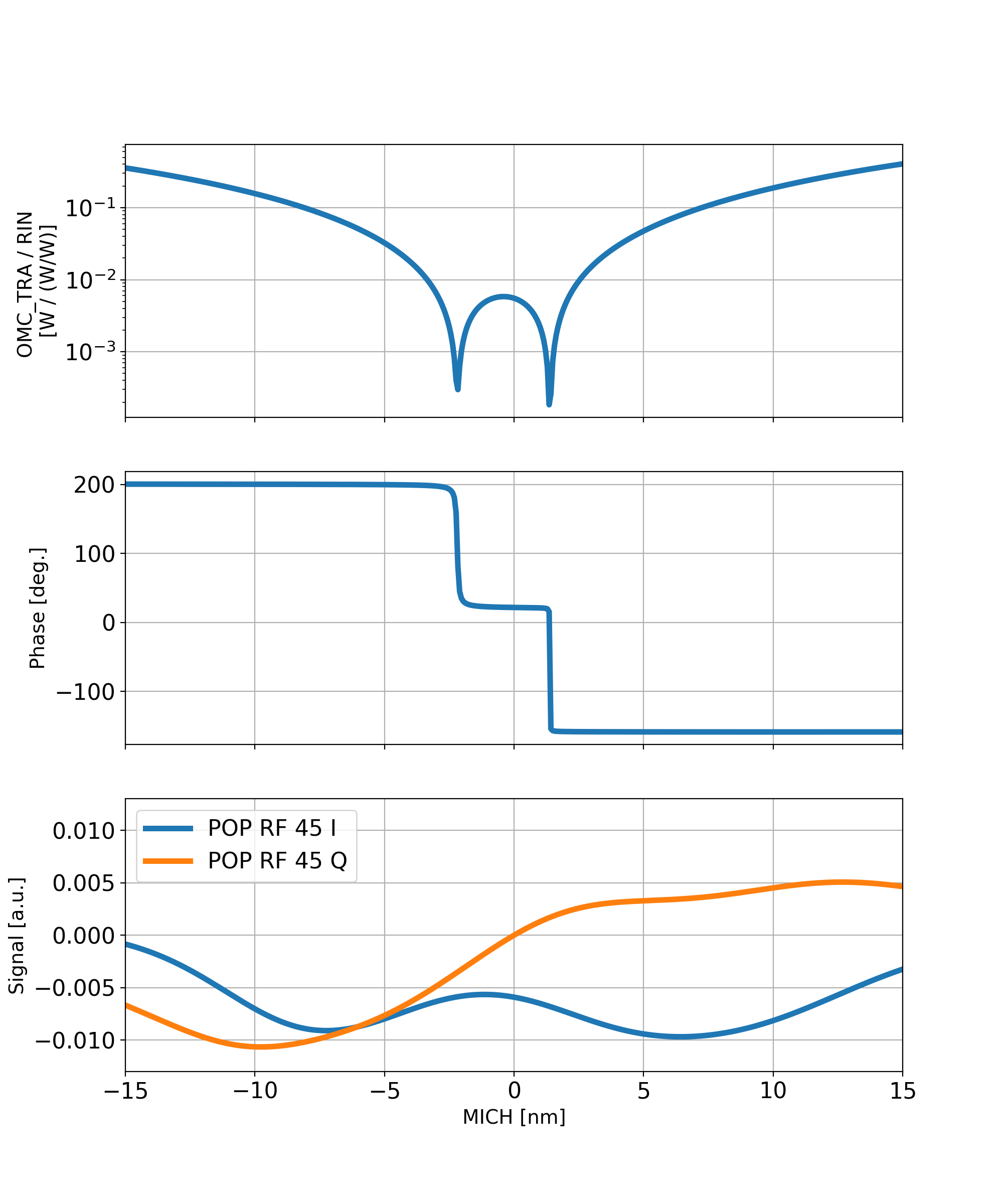
Here's another update to previous simulation of the effect of the optical path distortion (OPD) in ITMY due to the point absorber (following up on 47027 and 46952).

Simulation details:

Results:

Images attached to this report
Comments related to this report
gabriele.vajente@LIGO.ORG - 13:43, Wednesday 27 February 2019 (47162)

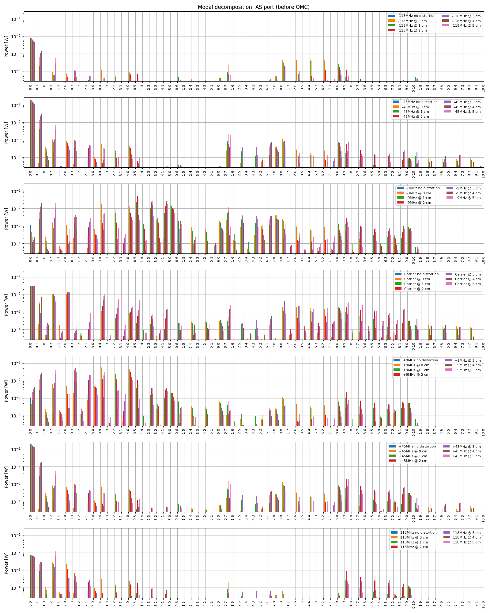
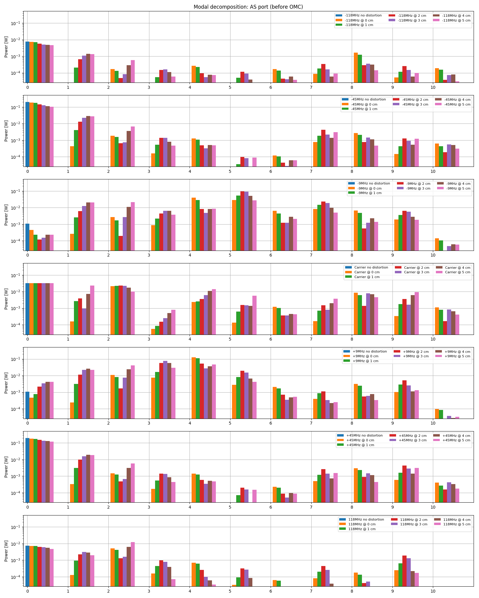
The two plots below show the mode content at the OMC input as a function of the point absorber position. The input power is 26 W and the modulation depth is 0.2 for 9 MHz and 45 MHz and 0.1 for 118 MHz. The first plot shows the decomposition into all modes, while the second shows the total for each order.


Images attached to this comment
gabriele.vajente@LIGO.ORG - 14:16, Tuesday 05 March 2019 (47305)

In the worst case scenario, with the point absorber at about 2cm from the beam center, the largest TEM9 mode has about 5 mW of power, so five times more than what initially reported in 47027. This means that (assuming all the TEM9 mode is transmitted by the OMC) we would need a RF9 RIN of about 1e-7 /rHz to explain the DARM excess noise.

H1 CDS (GRD)
david.barker@LIGO.ORG - posted 09:35, Wednesday 27 February 2019 (47156)
h1guardian1 reboot to install latest guardian code and OS patches

reboot at 09:31 PST

H1 DAQ (CDS, DAQ, SYS)
richard.mccarthy@LIGO.ORG - posted 09:27, Wednesday 27 February 2019 (47155)
LVEA-AUX network switch problems.

The network switch in the CER had problems this morning. It spontaneously rebooted several times. I am fairly confident it is a power supply problem which we would generally not notice if the second supply was installed but in this case it was not.  I have installed the second supply and will finish installing the 48V DC Feed to the switch as the backup supply to fix this situation.

This posed a problem for Peter K in the PSL as he could not see his normal video screens while the system rebooted.

H1 SUS (AOS)
thomas.shaffer@LIGO.ORG - posted 09:08, Wednesday 27 February 2019 - last comment - 10:52, Thursday 28 February 2019(47152)
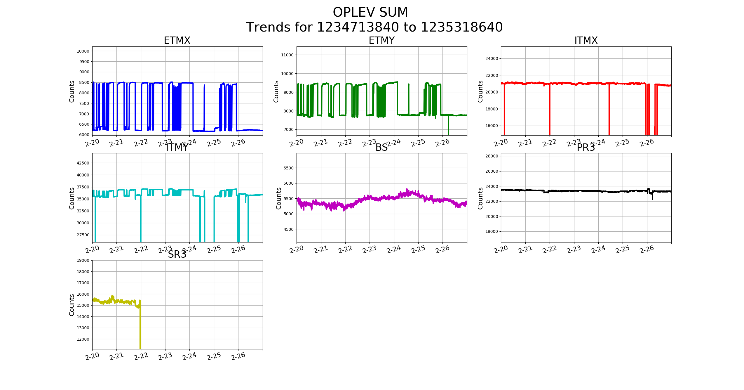
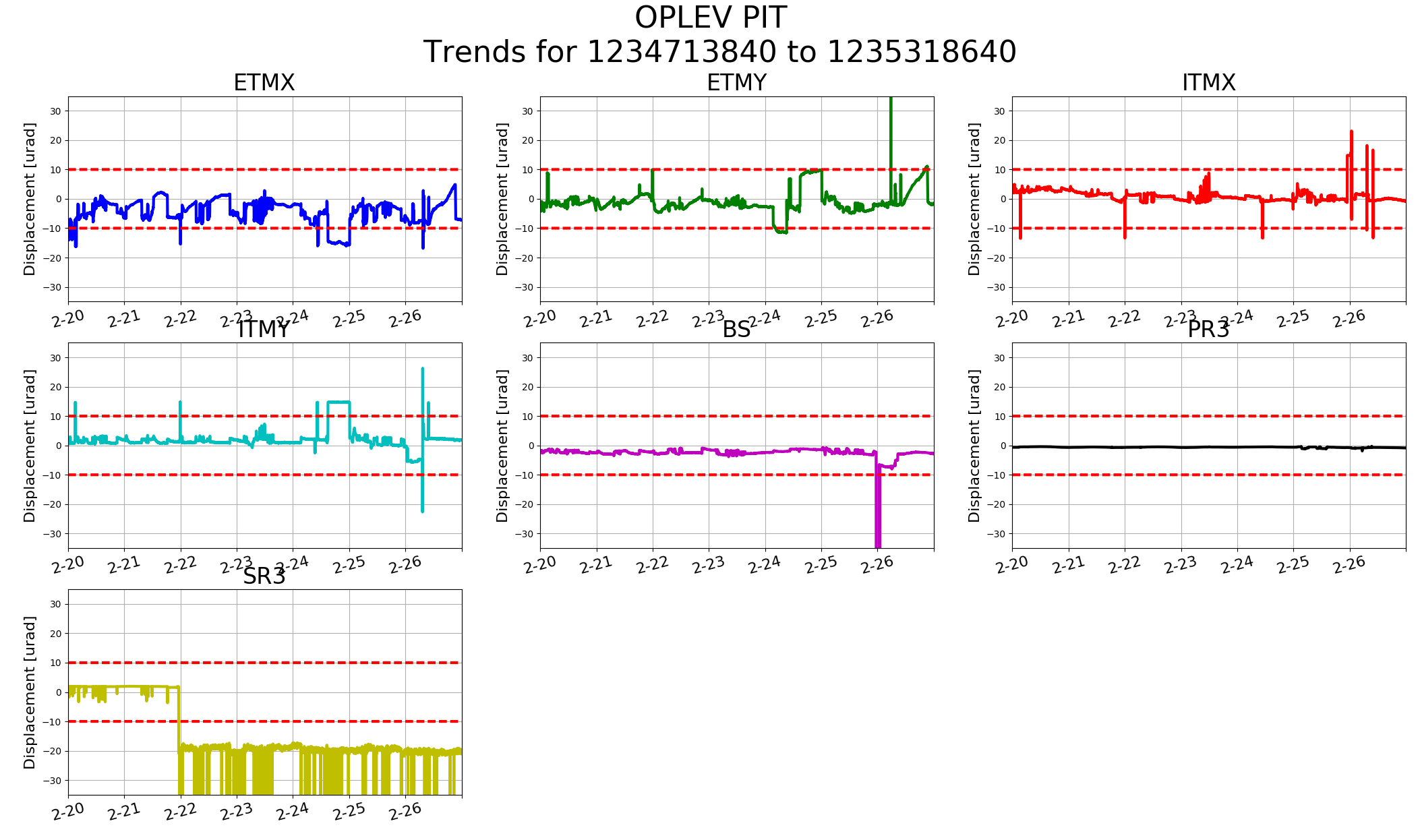
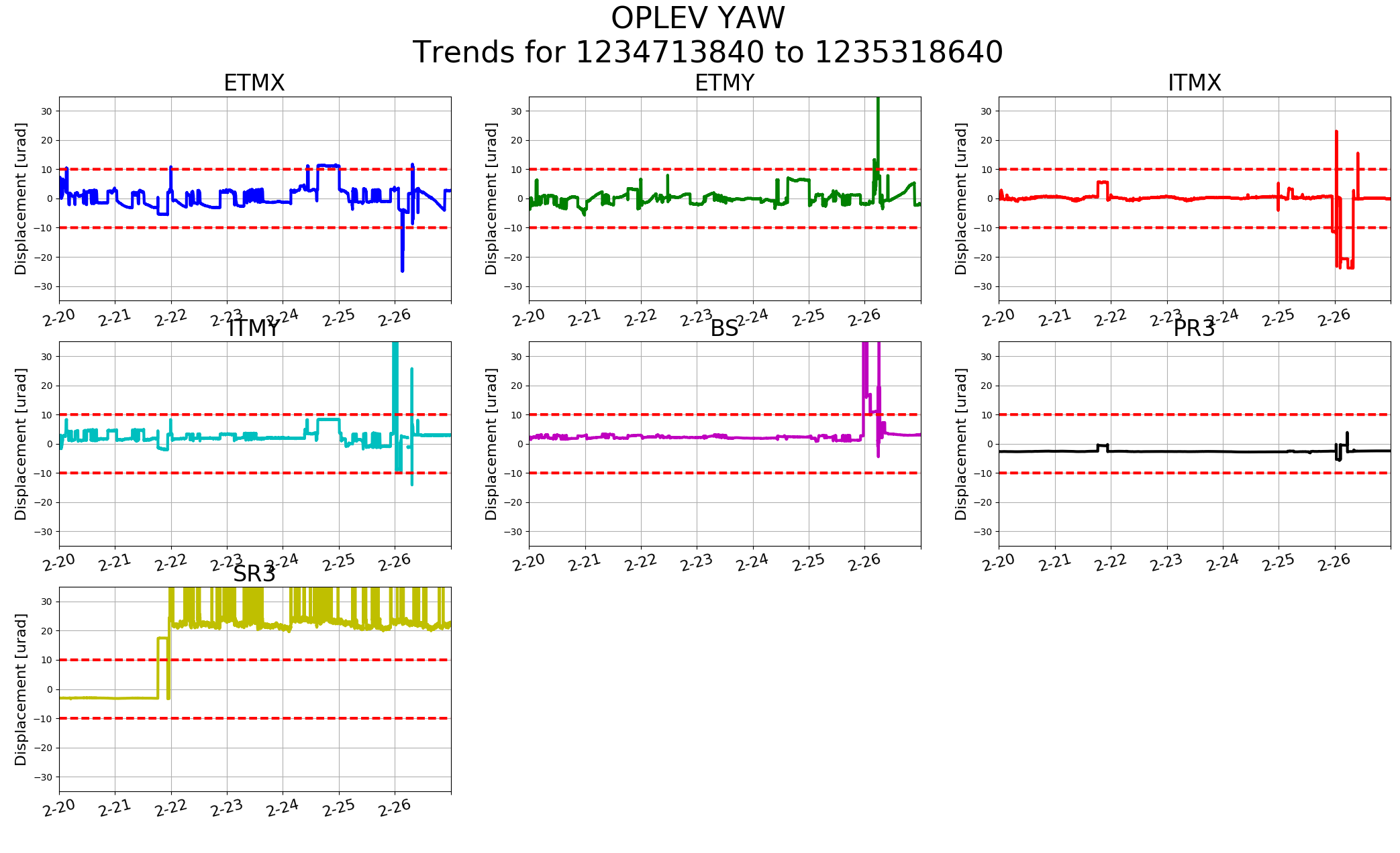
Optical Lever 7 Day Trends

FAMIS11206

SR3 is a known problem, but besides that ETMX P is nearing 10urad.

Images attached to this report
Comments related to this report
edmond.merilh@LIGO.ORG - 15:27, Wednesday 27 February 2019 (47163)

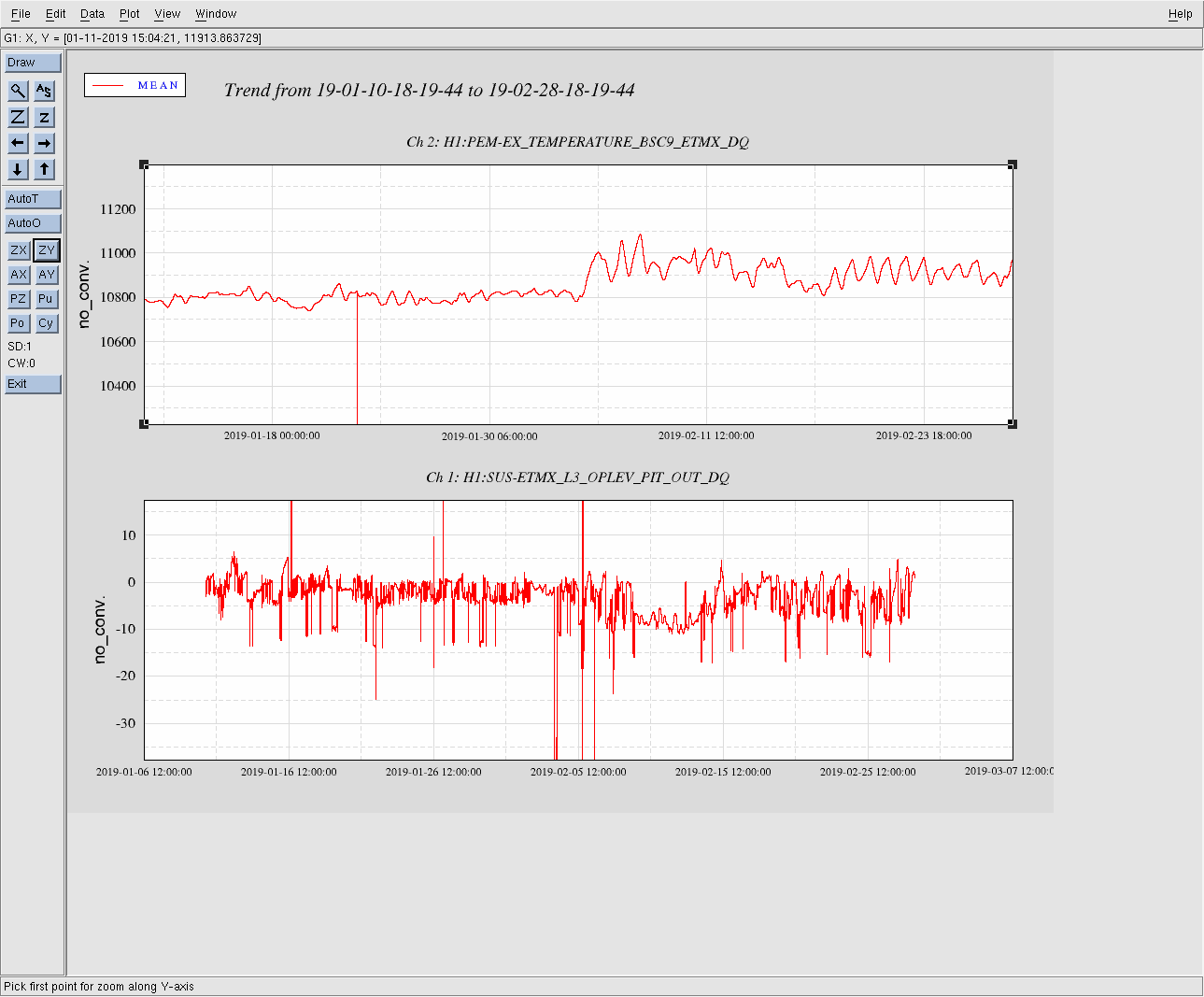
Perhaps the leaf springs on the suspension are sagging a bit due to the temperature. It looks like about -6.5 while trying to acquire DRMI. It isn't too, too bad but it could use some luvin'. I wasn't able to make it to the ends last Tuesday.

edmond.merilh@LIGO.ORG - 10:52, Thursday 28 February 2019 (47186)

It looks to be the case.

Images attached to this comment
H1 ISC (ISC)
rich.abbott@LIGO.ORG - posted 19:29, Tuesday 26 February 2019 - last comment - 11:58, Thursday 29 September 2022(47146)
Mysteries of OMC Grounding Revealed (?)
Summary:  Looked into the grounding issue as relates to the OMC and potential for coupling of ground related noise (including power line harmonics) to OMC length.

It is well known that there is a grounding anomaly inside HAM6 due to a metal cable bracket on the suspended OMC breadboard.  See:
https://alog.ligo-wa.caltech.edu/aLOG/index.php?callRep=41709

A detailed analysis of the documentation (as listed on the attached PDF) indicates that there should not be such a coupling, however it appears as though there is.  This probably means there is an error in the documentation.  If this ground path exists, then a method is suggested where a single cut to the shield-to-backshell connection may result in a more favorable situation with respect to the OMC grounding and shielding.

A few quick measurements should be made (aided by the attached cartoon) to verify the actual grounding configuration, then a breakout board could be added to accomplish the needed shield break such that the theory could be put to test.  If there is a ground connection, as suspected, it would be interesting to know if the same situation exists at LLO, or if it's just a defect in the wiring exclusive to LHO.
Non-image files attached to this report
Comments related to this report
koji.arai@LIGO.ORG - 23:24, Tuesday 26 February 2019 (47149)

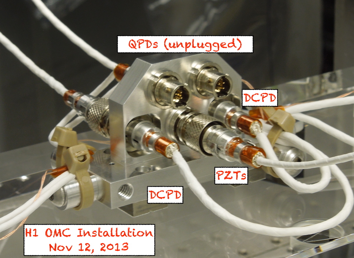
I went through the installation pictures of the H1 OMC back in 2013. I found some photos that show the shields of the mighty mouse connectors are all connected to the connector shells. This means that they are all connected at the metal cable harness. => (D) and (E) in Rich's attachment are connected.

I found the similar photos for L1 OMC and it has the same configuration.

Images attached to this comment
rich.abbott@LIGO.ORG - 20:48, Wednesday 27 February 2019 (47173)
Thanks Koji.  I believe what you say, but still have no explanation for why the PZT shield is not connected to the QPD shield?  I now fully understand the issue with the DCPD (more to follow on that as I catch up on new cartoons and words)
keita.kawabe@LIGO.ORG - 16:17, Wednesday 28 September 2022 (65144)

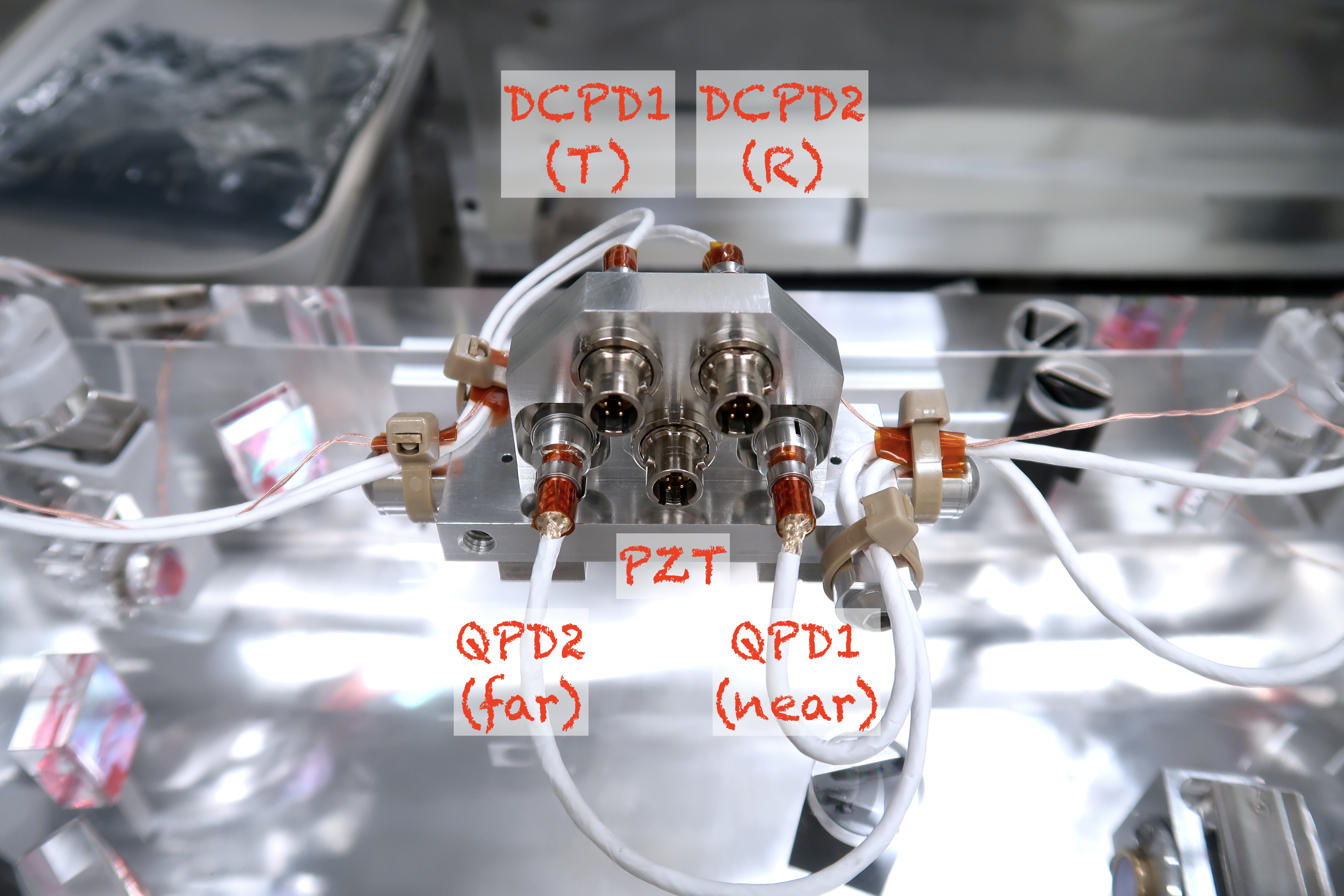
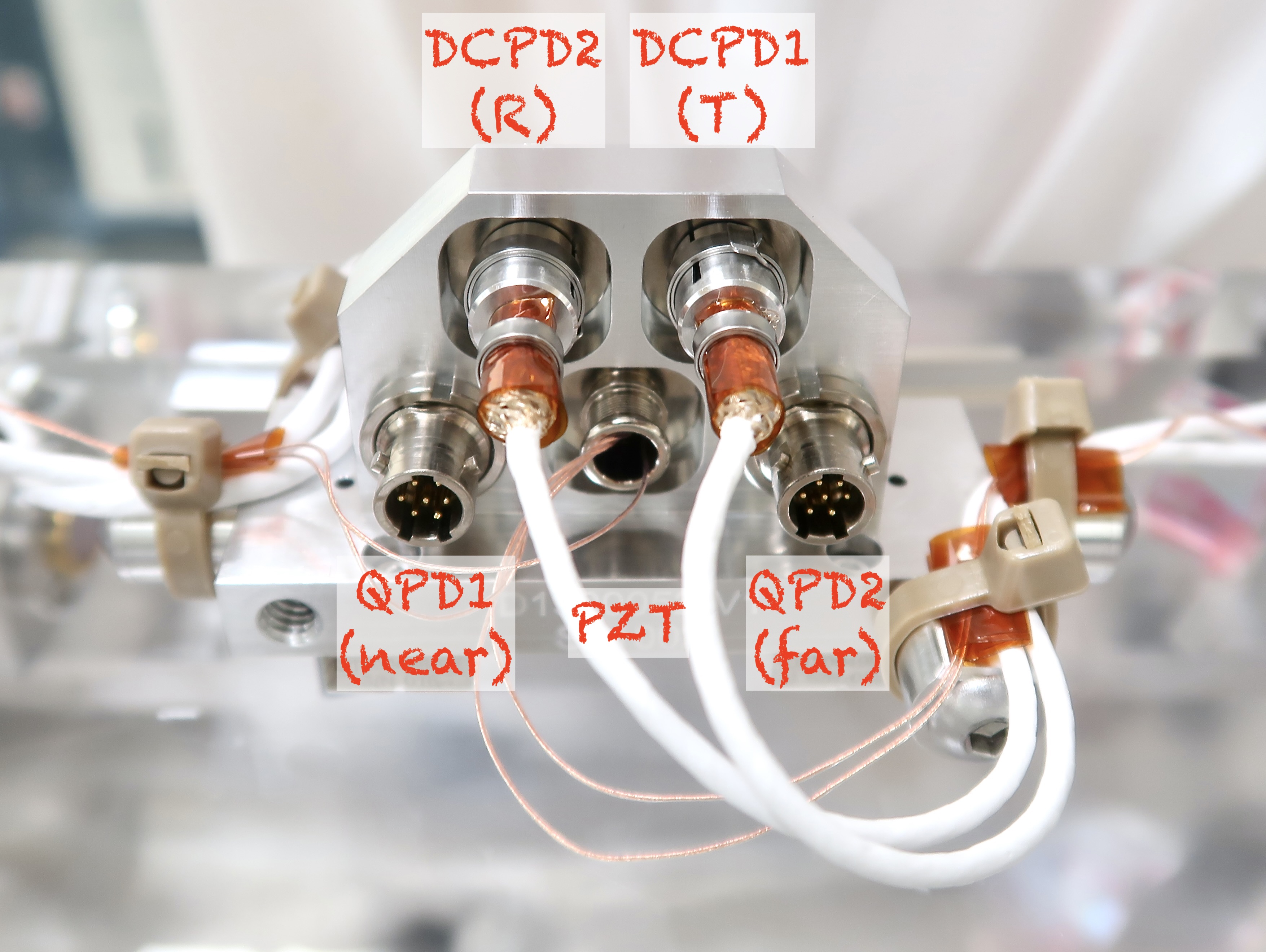
Later-than-too-late comment, but just for posterity, labels for DCPDs and QPDs are swapped in Koji's pictures.

Look at the exposed connectors with 4 pins each in the 2nd picture. Real QPD MM connector has 7 pins (https://dcc.ligo.org/LIGO-D1300375).

koji.arai@LIGO.ORG - 16:43, Wednesday 28 September 2022 (65145)

Comfirmed. I agree with Keita.

Images attached to this comment
keita.kawabe@LIGO.ORG - 11:46, Thursday 29 September 2022 (65151)

Are these also the pictures of H1 OMC?

koji.arai@LIGO.ORG - 11:58, Thursday 29 September 2022 (65152)ISC

Strictly speaking, no. These are the pictures of OMC #002, which was the former (original) LHO OMC and has been refurbished to be the new LLO OMC.

H1 TCS (TCS)
daniel.vander-hyde@LIGO.ORG - posted 13:41, Tuesday 26 February 2019 - last comment - 12:04, Wednesday 27 February 2019(47132)
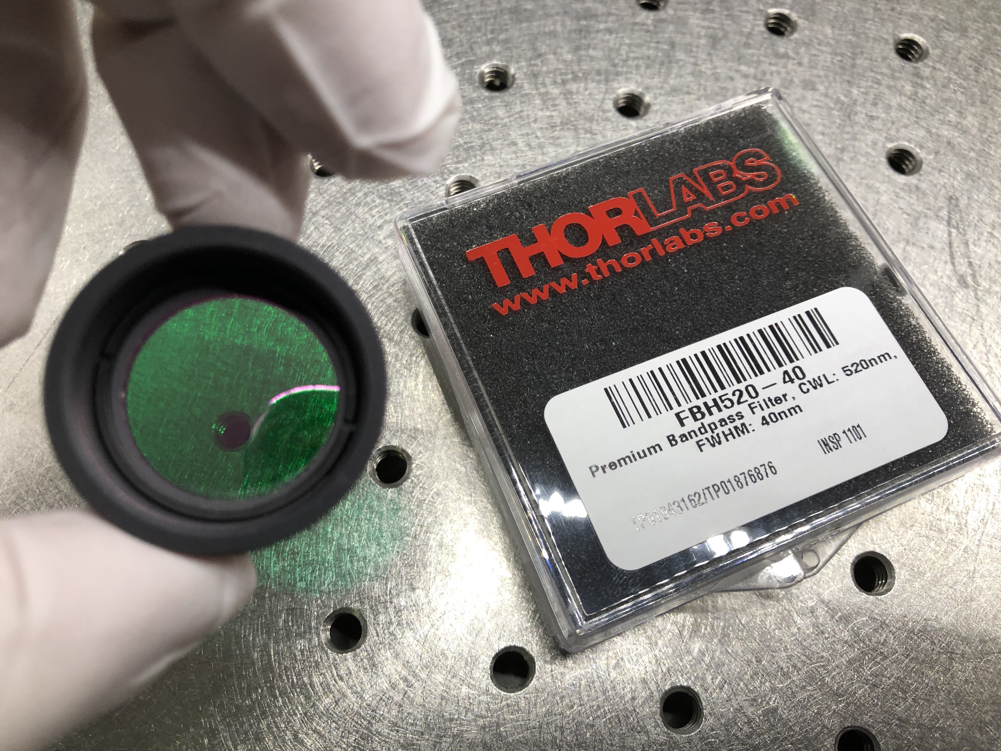
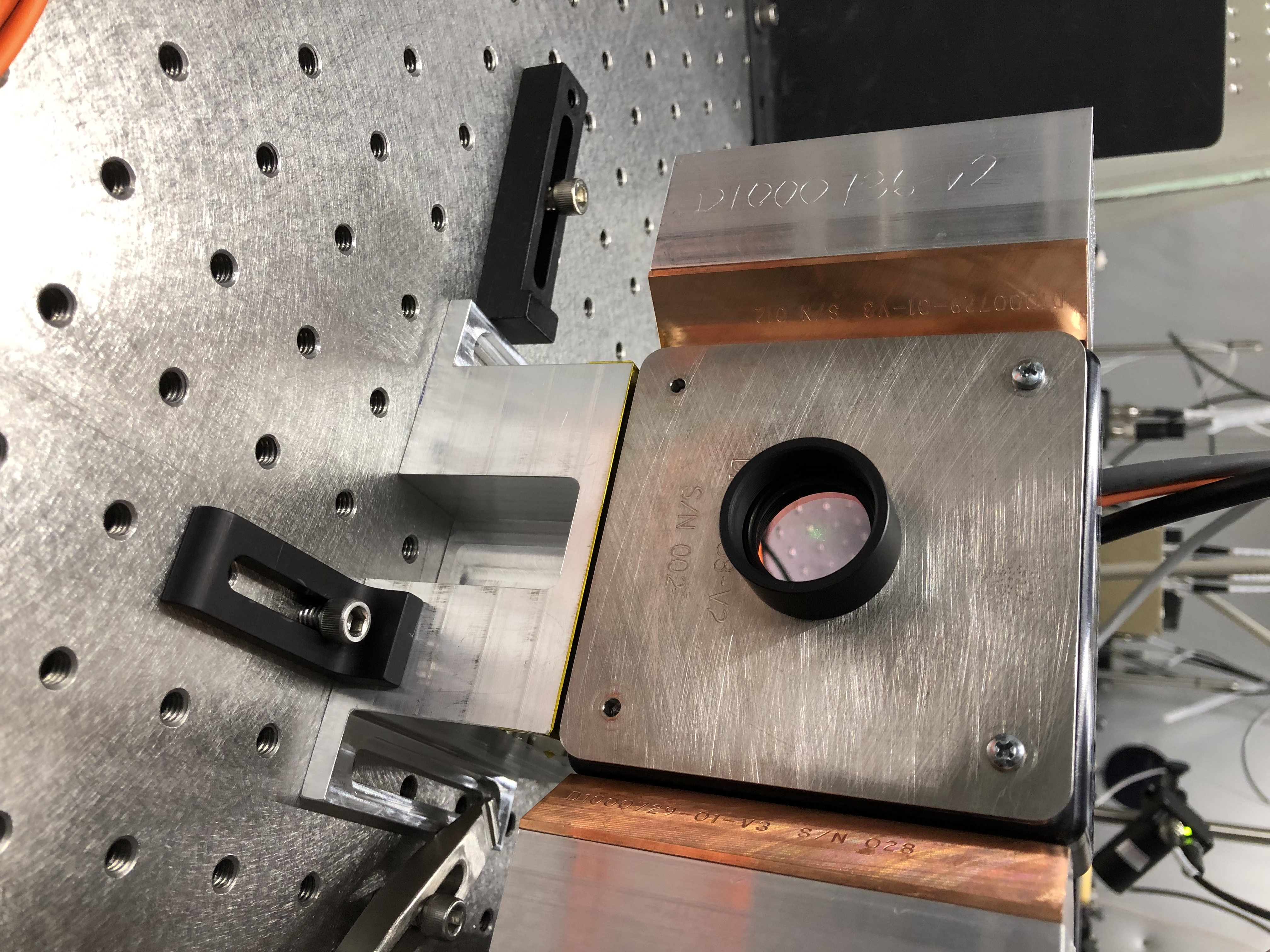
ETMY HWS green bandpass filter installed

TJ, Dan B., Danny V. 

Images attached to this report
Comments related to this report
daniel.brown@LIGO.ORG - 12:04, Wednesday 27 February 2019 (47160)

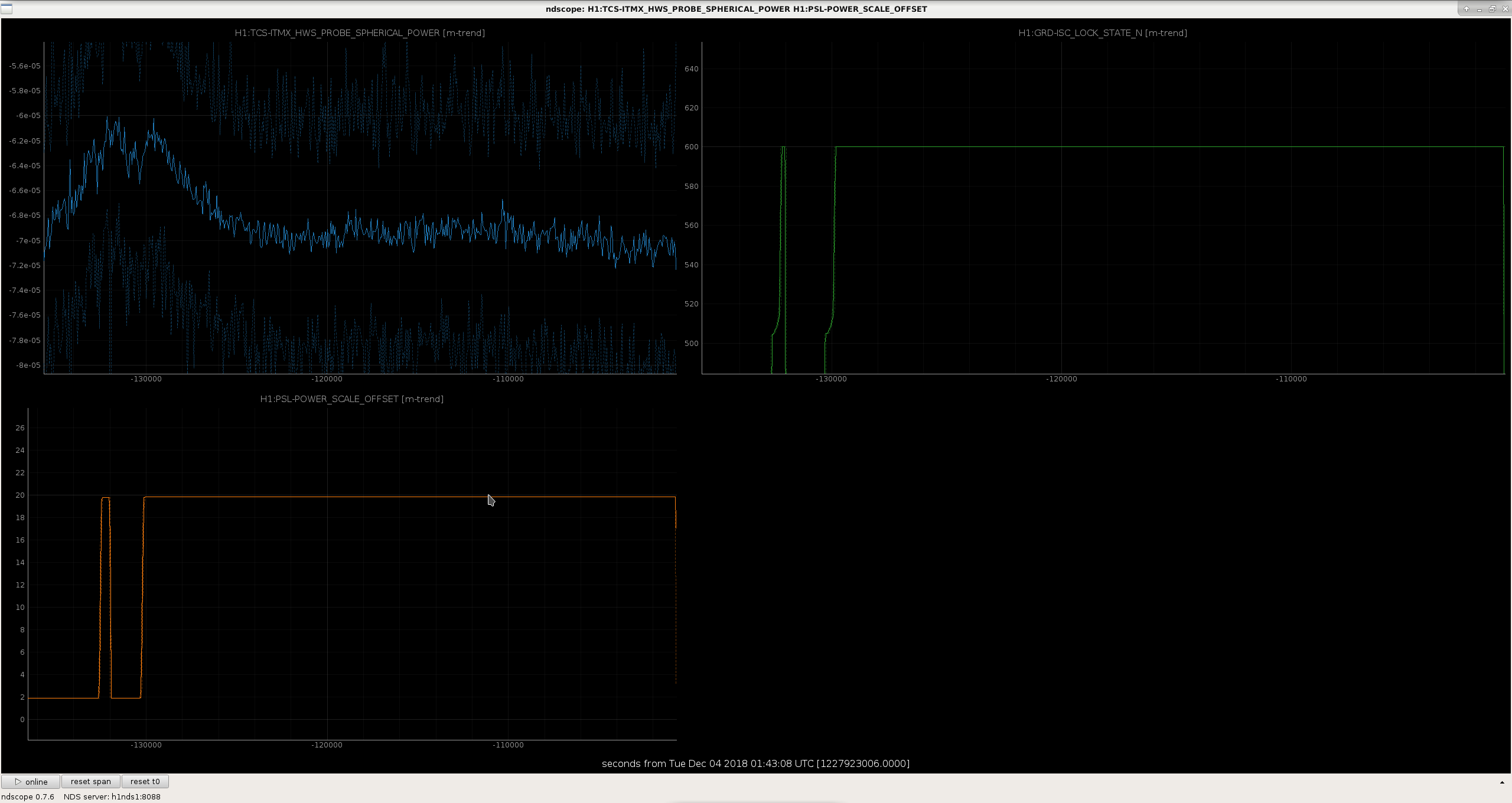
This filter has not fixed the issue with the lensing being negative on powerup on ETMY

Displaying reports 42881-42900 of 88649.Go to page Start 2141 2142 2143 2144 2145 2146 2147 2148 2149 End