Displaying reports 43141-43160 of 88636.Go to page Start 2154 2155 2156 2157 2158 2159 2160 2161 2162 End
Reports until 17:43, Monday 11 February 2019
H1 SQZ
sheila.dwyer@LIGO.ORG - posted 17:43, Monday 11 February 2019 (46892)
squeezer beam clipping checks

Sheila, Terry, Nutsinee

This is a late alog of work done last Thursday afternoon.   The main message is that we don't think we are close to clipping with the squeezer beam in the interferometer alignment used for the squeezing injection test on Tuesday

Checking the range on SRM alignments:

H1 General
jonathan.hanks@LIGO.ORG - posted 16:07, Monday 11 February 2019 (46891)
The site has been closed since Saturday due to weather.

Due to the winter storms the site was closed on Saturday.  In an email on Saturday

All,

The LIGO Hanford site is closed until further notice. Adding to Bubba's earlier note about site conditions, the roads to the LHO site are now closed and/or experiencing blizzard conditions. In the interim, any personnel with a need for staff presence on site should contact Mike Landry or Jeff Jones. 

Best Regards,

Jeff Jones

Then Sunday night

All,

Given another winter storm warning for later this evening, the LIGO Hanford site remains closed until further notice. Personnel are not to report to work on site Monday morning. While this closure remains in effect, any personnel with a need for staff presence on site should contact Jeff Jones or Mike Landry. 

Best Regards,

Jeff Jones
H1 CDS
david.barker@LIGO.ORG - posted 21:05, Sunday 10 February 2019 - last comment - 08:24, Monday 11 February 2019(46885)
h1iopsusb123 has DAC error, requires a restart

It looks like h1iopsusb123 (SUSITM[X,Y],BS) had a timing error which resulted in a DACKILL, meaning all DAC outputs are 0.0V (and the 18bit-DAC AI chassis have disabled their outputs). A restart of all models on h1susb123  (/etc/startWorld.sh) is required to clear the problem.

Comments related to this report
david.barker@LIGO.ORG - 08:24, Monday 11 February 2019 (46886)

Would the next person in the control room please call me on my cell and we can get this system running again.

H1 ISC
jameson.rollins@LIGO.ORG - posted 01:19, Saturday 09 February 2019 - last comment - 12:41, Friday 15 February 2019(46883)
Exploring 9MHz RIN situation

[Rana, Jamie]

We spent the evening trying to get more measurements of the 9MHz RIN situation, basically redoing what was done in LHO log 46586.  We went to ITMY single-bounce and locked OMC on carrier, then went to PRMI and locked OMC on 9MHz.  I'll post plots tomorrow.

FYI the OMC and PRMI configurations might be a little bit funky.  We didn't get to reset everything yet to get back to low noise, just in case any one tries to brave the snow to get back out here.

Comments related to this report
jameson.rollins@LIGO.ORG - 14:19, Monday 11 February 2019 (46889)

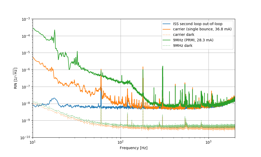
Friday night Rana and I re-measured the relative intensity noise (RIN) in the carrier and 9MHz sideband at the OMC DCPD.  We believe we got a lower noise measurement (first attachment) than what Craig and Koji measured previously (LHO 46586) by:

  • increasing the OMC length dither amplitude by x300 (the dither amplitude had been tiny, we should probably address this permanently)
  • using PRMI lock for the 9MHz measurement

For the carrier measurement used single bounce off of ITMX with 25W input, and for the 9MHz used PRMI (where the 9MHz sideband is largest) with 35W input.

We don't see any excess RIN in the 9MHz above 300 Hz.

1233733816 carrier measurement
1233738050 9MHz measurement
1233738400 dark noise measurement
Images attached to this comment
gabriele.vajente@LIGO.ORG - 20:24, Monday 11 February 2019 (46890)

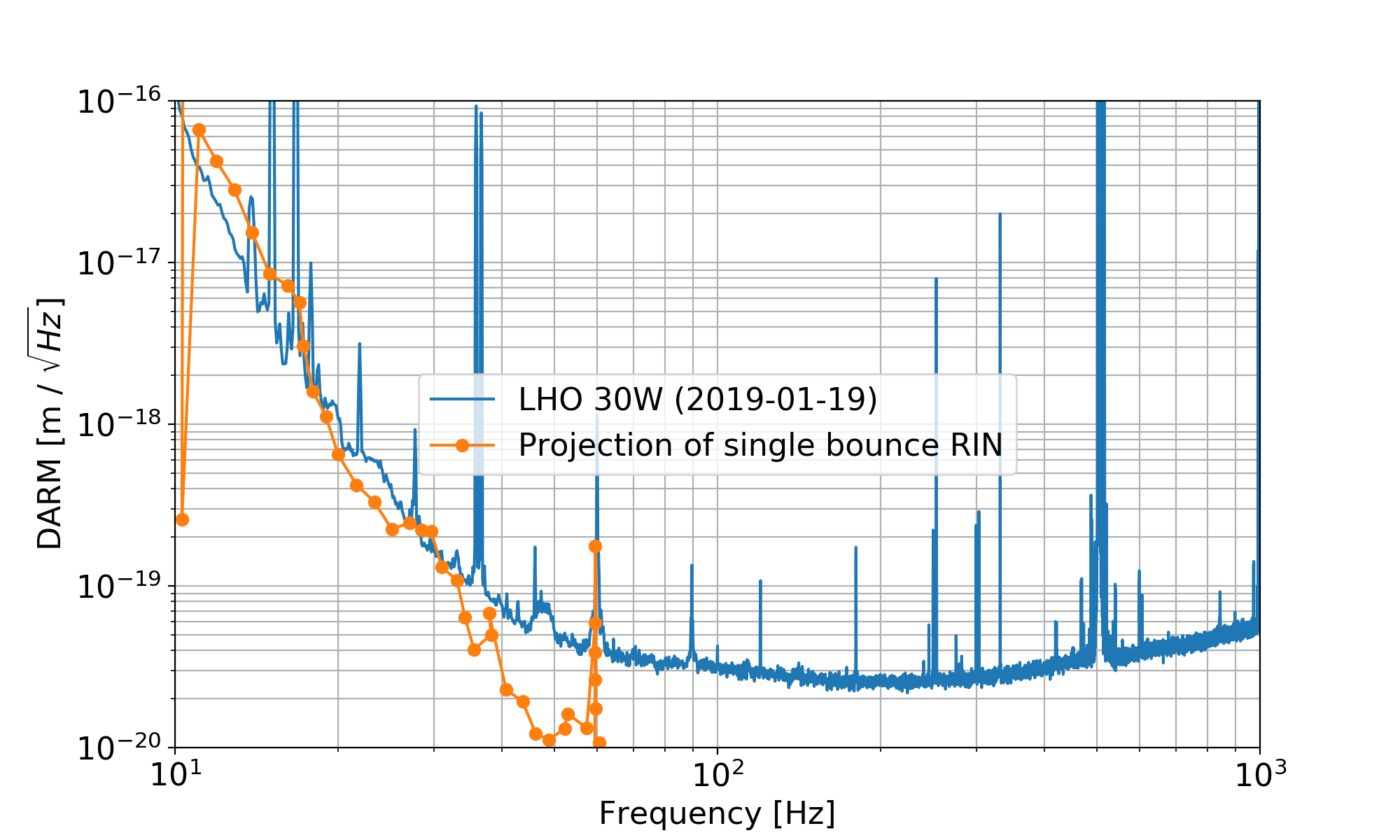
1) the carrier RIN in your plot at 30 Hz is in the 1e-7 region. Do we believe this excess above the ISS second loop measurement and above the noise floor? Or is it OMC length noise?

I’m asking because a RIN of 2e-7 is what we need to be limiting DARM, see https://alog.ligo-wa.caltech.edu/aLOG/index.php?callRep=46759

If we believe the carrier single bounce RIN measured by Jamie and Rana, and use the radiation pressure intensity noise coupling (based on 8% power imbalance and matching Craig's measurement in 46817), we get something pretty close to the DARM noise:


2) same question for the excess SB RIN? Is that PRMI control noise?

Images attached to this comment
daniel.sigg@LIGO.ORG - 10:57, Tuesday 12 February 2019 (46900)

For 35W input power, the ISS inner PD shows 27.3mA, whereas the outer shows 29.7mA.

jameson.rollins@LIGO.ORG - 15:10, Wednesday 13 February 2019 (46935)

Note I think it's possible that we were looking at the 45MHz sideband in the PRMI lock, rather than the 9MHz sideband.  We will attempt to retake this measurement once the IFO is recovered.

rana.adhikari@LIGO.ORG - 12:41, Friday 15 February 2019 (46964)ISC

it seems that the OMC length lock is not strong enough to measure low RIN - this is why the increase of the OMC length dither decreases the RIN.

Most of the low frequency peaks are due to acoustics - we were using the QPDs for OMC-ASC instead of angular dither.

H1 ISC (CAL, SUS)
sheila.dwyer@LIGO.ORG - posted 19:14, Friday 08 February 2019 (46861)
DARM actuation back on ETMX, UIM crossover more stable

Sheila, Keita, 

Summary:

We have switched DARM control back to ETMX for ESD, PUM and UIM, and we have reshaped the UIM filters to make the cross over of the UIM with the rest of the DARM loop more stable. 

Details:

We used ETMY L1+L2 + ETMX ESD as our DARM actuator for most of the fall, but in early January a scattering problem appeared in EY which caused us to move the DARM actuator to ETMX completely 46329.  Last Friday the ETMX configuration stopped working, 46751, so we have been using the split actuator this week.  We wanted to move the DARM actuator back to avoid possible scattering problems, because the calibration team has been working to calibrate EX, and we want to do this before retuning the LSC feedforwards. 

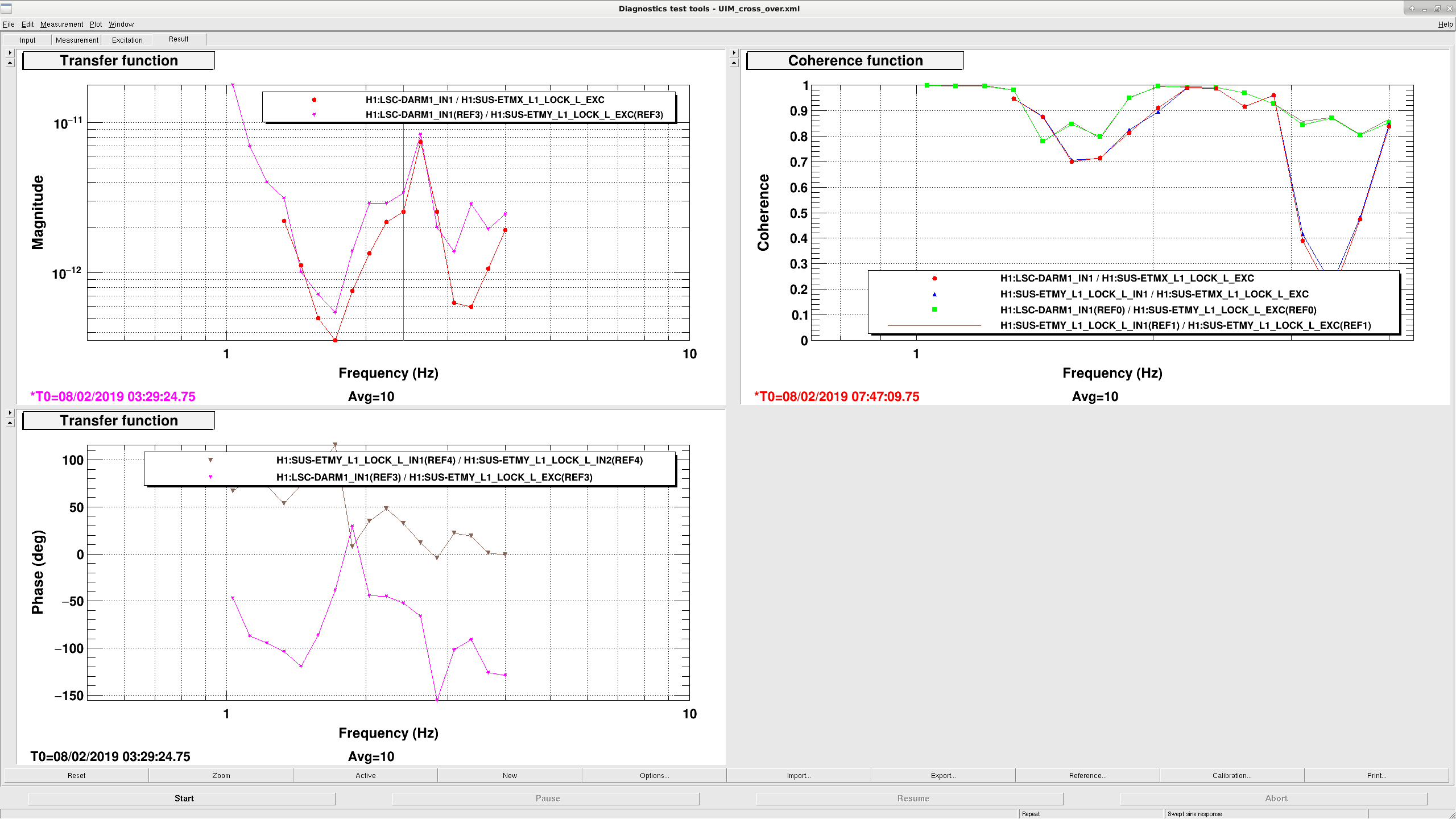
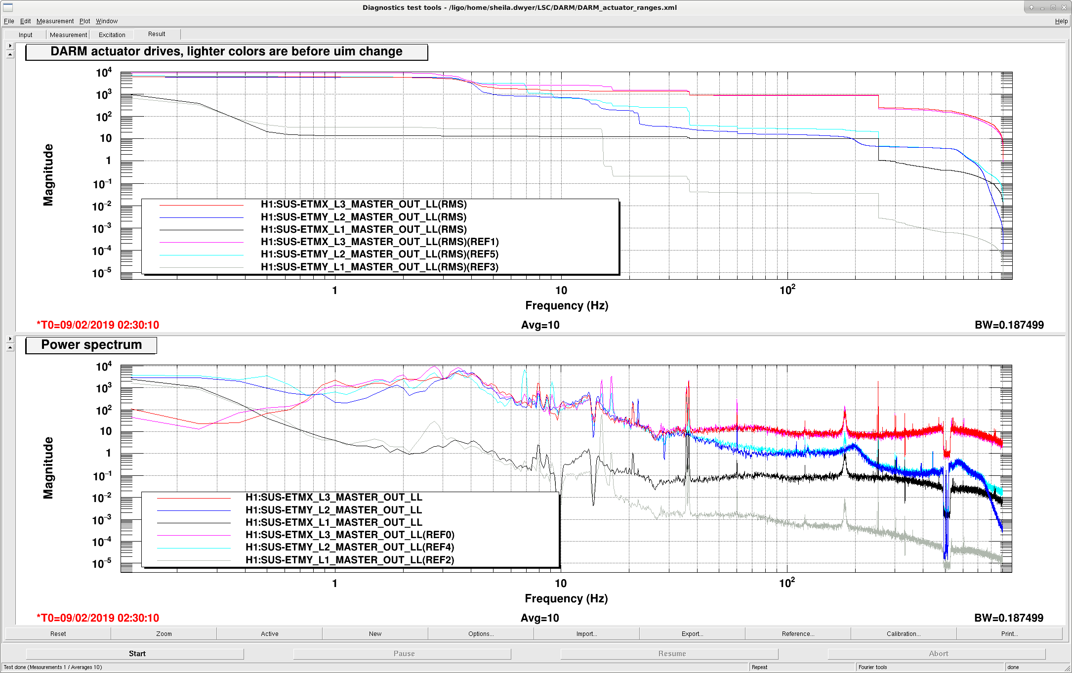
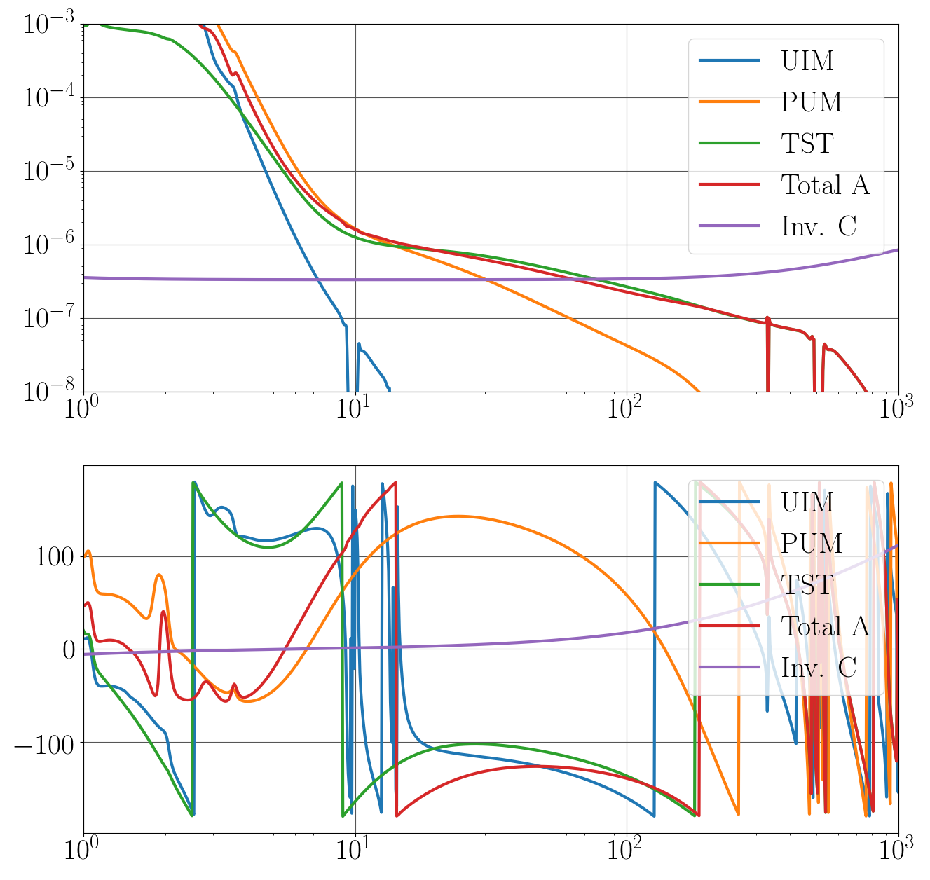
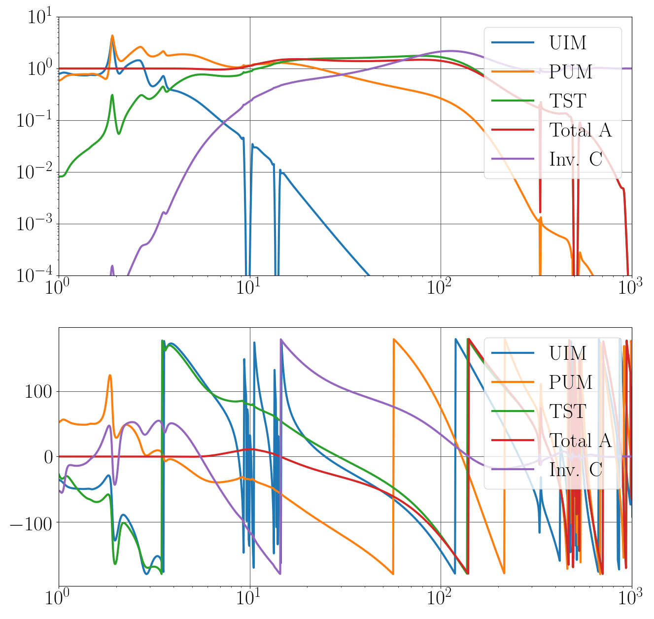
Last Friday when we were trying to switch from EY to EX, we measured the gain of the ESDs to DARM and the PUMs to DARM, and they were well matched between EX and EY.  The attached screenshot shows a comparison of the response of DARM to UIM drive for ETMX and ETMY that we made last night.  These were taken with a gain of 0.4 in L1LOCK L for ETMX and 0.6 for ETMY, which was based on an old measurement of the relative strengths (from before the ETMs were replaced).  This shows that with these old relative gains, we were using 25% too low a gain for the ETMX UIM offloading compared to ETMY.  Instead of 0.4 for ETMX we should have been using 0.53 as a L1 LOCK gain.  

The first two PDFs show a model of the DARM loop and its crossovers as it has been, compared with measurements taken in the actuator configuration used this week (ETMX ESD, ETMY UIM and PUM).   These actuator models are taken from the CAL front end filters, Evan Goetz helped me to compare parts of this to pyDARM.

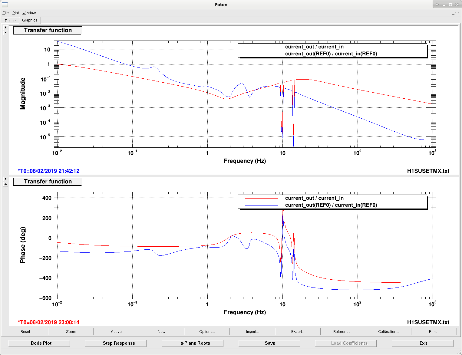
The crossover measurements are taken at L2 LOCK L IN1/IN2 and L1 lock in2/in1.  If you think of the loop as a common path C, slow path S and fast path F, these measurements are of CS/(1-CF) which is approximately -S/F We would like to avoid the situation where the two actuators are canceling each other's motion which is approximately the same as staying away from a unity gain point with 0 phase in this measurement. You can see in the open loop model that the gain of the UIM and PUM paths are nearly equal from about 0.5 Hz to almost 3 Hz, which is not ideal, and that they are close to being out of phase.  We have know that this wasn't ideal for a while, but until last Friday we weren't having much trouble with the stability of the DARM loop so we have left it alone. The second attached plot shows a comparison of the old UIM lock L filter to a new one that Keita and I made today.  We replaced the UIM filter with this filter, and increased it's gain by a factor of 2 so that the gain setting for the L1 lock is now 1.06.  The 3rd and 4th attached PDFs show the DARM model with the new filter and gain for the uim.  The UIM crossover is now more stable.  The model underestimated the gain of the UIM path when it was locked on ETMY and over estimates the gain on ETMX, which we don't understand, but there is room to increase the UIM gain.

The third attached screenshot shows the rms drive to the suspensions before and after this change; we have room to increase the UIM gain more.  

These changes are in the guardian now.  If there are any problems in the LOWNOISE_ESD_ETMX state, you can reset the use_EX_L1L2 flag back to False. 

Images attached to this report
Non-image files attached to this report
H1 General
corey.gray@LIGO.ORG - posted 16:03, Friday 08 February 2019 (46868)
DAY Operator Summary (Covering Jim's shift)

Covering latter part of Jim's shift....

Commissioning Status:  H1's ASC Loops were taking forever to converge.  Gabriele is moving stuff around to help them converge & eventually went to NOMINAL_LOW_NOISE at 18:48.

H1 PEM
corey.gray@LIGO.ORG - posted 16:01, Friday 08 February 2019 (46878)
Dust Monitors

Increased the Dust Monitor Alarm Settings by x3 in the LVEA, EX, & EY since they were alarming most of the day with no activity in the buildings.  

(I'm thinking I should bump them up a little more since EY just alarmed at 480, but maybe that's OK to keep track of dust events which might come up?)

H1 SYS (CAL, GRD, SYS)
jameson.rollins@LIGO.ORG - posted 15:44, Friday 08 February 2019 - last comment - 14:58, Wednesday 13 February 2019(46877)
Test of H1 IFO OBSERVATION bits

We are about to conduct a test of the H1 OBSERVATION bit behavior (see lho elog 46812).  The following bits will be flipped during this test:

Will respond to this log when the test is complete.

Comments related to this report
jameson.rollins@LIGO.ORG - 16:12, Friday 08 February 2019 (46879)

This test is now complete.  Times of bit flips will be posted soon.

jameson.rollins@LIGO.ORG - 16:55, Friday 08 February 2019 (46880)

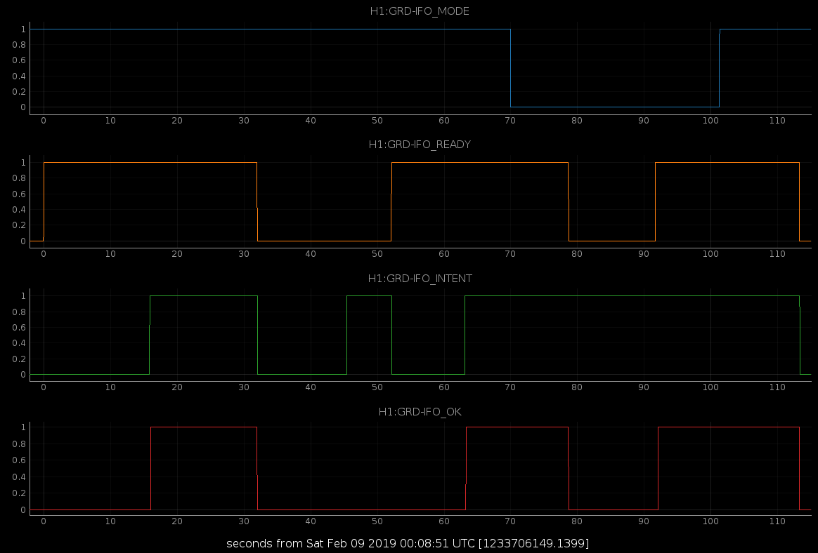
Test began at roughly 11233706149.  IFO top node set to monitor a single TEST node used as a proxy for the entire system.  Initial values:

  • H1:GRD-IFO_MODE = 1 ("MANAGED")
  • H1:GRD-IFO_READY = 0
  • H1:GRD-IFO_INTENT = 0
  • H1:GRD-IFO_OK = 0

Time sequence is as follows:

  1. T0 = 11233706149 (all bits 0/False)
  2. +000.1250: READY=1 (test begins, TEST node achieves "lock" (OK), system achieves READY)
  3. +015.8750: INTENT=1 ("OBSERVE" state requested)
  4. +016.0625: OK=1 ("OBSERVE" state achieved)
  5. +032.0000: OK=READY=INTENT=0 (TEST node "lock loss")
  6. +045.4375: INTENT=1 ("OBSERVE" state requested)
  7. +052.1250: READY=1, INTENT=0 (TEST node achieves OK, INTENT reset due to MANAGED mode)
  8. +063.1250: INTENT=1 ("OBSERVE" state requested)
  9. +063.3125: OK=1 ("OBSERVE" achieved)
  10. +070.0000: MODE=0 (MODE set to "AUTO")
  11. +078.6875: READY=OK=0 (TEST node "lock loss", INTENT remains =1 due to AUTO mode)
  12. +091.6875: READY=1 (TEST node achieves OK)
  13. +092.1250: OK=1 ("OBSERVE" achieves OK, previous INTENT respected due to AUTO mode)
  14. +101.3125: MODE=1 (mode reset to MANAGED)
  15. +113.3125: READY=INTENT=OK=0 (TEST node "lock loss", conclusion of test)


Images attached to this comment
madeline.wade@LIGO.ORG - 13:29, Wednesday 13 February 2019 (46896)

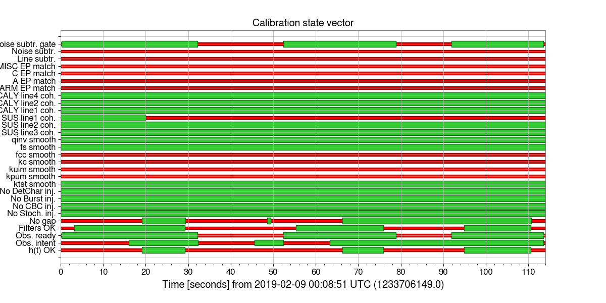
The GDS-CALIB_STATE_VECTOR did catch transitions, but we're off by 1-4 clock cycles on each of the transitions.  The relevant bits in the attached plot are Obs. ready, which corresponds to the READY state obtained from the GRD-IFO_READY channel and Obs. intent, which corresponds to the INTENT state obtained from the GRD-IFO_INTENT channel.  The first READY transition gets picked up by CALIB_STATE_VECTOR 1 clock cycle late and all future READY transitions are 3 clock cycles late.  All transitions from INTENT=0 to INTENT=1 are 3 clock cycles late (I think, but see question in purple below), and all transitions from INTENT=1 to INTENT=0 are 4 clock cycles late.  

Summary of relevant transitions from Guardian and how CALIB_STATE_VECTOR picked it up:

  1. T0 = 11233706149 (all bits 0/False) <- Correctly picked up by CALIB_STATE_VECTOR
  2. +000.1250: READY=1 (test begins, TEST node achieves "lock" (OK), system achieves READY) <- CALIB_STATE_VECTOR picked up READY transition at +000.1875 (1 clock cycle late)
  3. +015.8750: INTENT=1 ("OBSERVE" state requested) <- CALIB_STATE_VECTOR picked up INTENT transition at +016.0625 (3 clock cycles late).  If this lines up with 3. then it is 3 clock cycles late, but if it lines up with 4. then it is on time.  I had thought 3. meant GRD-IFO_INTENT was set to 1; is that correct?
  4. +016.0625: OK=1 ("OBSERVE" state achieved) 
  5. +032.0000: OK=READY=INTENT=0 (TEST node "lock loss") <- CALIB_STATE_VECTOR picked up READY transition at +032.1875 (3 clock cycles late) and INTENT transition at +032.25 (4 clock cycles late).
  6. +045.4375: INTENT=1 ("OBSERVE" state requested) <- CALIB_STATE_VECTOR picked up INTENT transition at +045.625 (3 clock cycles late)
  7. +052.1250: READY=1, INTENT=0 (TEST node achieves OK, INTENT reset due to MANAGED mode) <- CALIB_STATE_VECTOR picked up READY transition at +052.3125 (3 clock cycles late) and the INTENT transition at 52.375 (4 clock cycles late)
  8. +063.1250: INTENT=1 ("OBSERVE" state requested) <- CALIB_STATE_VECTOR picked up INTENT transition at +063.3125 (3 clock cycles late)
  9. +063.3125: OK=1 ("OBSERVE" achieved)
  10. +070.0000: MODE=0 (MODE set to "AUTO")
  11. +078.6875: READY=OK=0 (TEST node "lock loss", INTENT remains =1 due to AUTO mode) <- CALIB_STATE_VECTOR picked up READY transition at +078.875 (3 clock cycles late)
  12. +091.6875: READY=1 (TEST node achieves OK) <- CALIB_STATE_VECTOR picked up READY transition at +091.875 (3 clock cycles late)
  13. +092.1250: OK=1 ("OBSERVE" achieves OK, previous INTENT respected due to AUTO mode)
  14. +101.3125: MODE=1 (mode reset to MANAGED)
  15. +113.3125: READY=INTENT=OK=0 (TEST node "lock loss", conclusion of test) <- CALIB_STATE_VECTOR picked up READY transition at +113.5 (3 clock cycles late) and the INTENT transition at +113.5625 (4 clock cycles late)


Images attached to this comment
jameson.rollins@LIGO.ORG - 14:58, Wednesday 13 February 2019 (46931)

Maddie, this was my fault, being both imprecise and looking at the leading edge of the transitions instead of when theey land on the value shown.  I've gone through with a finer toothed comb and updated the values to their precise values as recorded by the DAC (I also fixed the T0 GPS time, which accidentally had an additional digit):

  1. 1233706149
  2. +000.1250: READY=1
  3. +016.0625: INTENT=1
  4. +016.2500: OK=1
  5. +032.1250: OK=READY=0
  6. +032.1875: INTENT=0
  7. +045.5625: INTENT=1
  8. +052.2500: READY=1
  9. +052.3125: INTENT=0
  10. +063.2500: INTENT=1
  11. +063.4375: OK=1
  12. +070.1250: MODE=0
  13. +078.8125: READY=OK=0
  14. +091.8125: READY=1
  15. +092.2500: OK=1
  16. +101.4375: MODE=1
  17. +113.4375: READY=OK=0
  18. +113.5000: INTENT=0

I think this accounts for all the discrepancies that Maddie saw.  Apologies, Maddie.

LHO VE
kyle.ryan@LIGO.ORG - posted 15:27, Friday 08 February 2019 (46876)
Leaving Y-mid instrument air off for the weekend.

May need this on again next week.

H1 CAL
ling.sun@LIGO.ORG - posted 14:37, Friday 08 February 2019 - last comment - 12:33, Monday 11 February 2019(46875)
Test O3 calibration uncertainty using 20190118 H1 model

Lilli Sun,

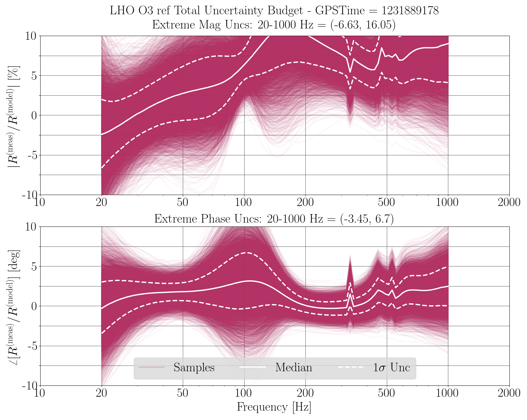
This is for H1 reference model uncertainty test (see 43260 for L1).

The 20190118 model is a bit confusing. The model parameters are rescaled according to 46605, which are not consistent with MCMC results. Using the model file and the MCMC results leads to systematic errors. Need to further investigate if the systematic error seen in the attached uncertainty plot is caused by the inconsistency.

Images attached to this report
Comments related to this report
ling.sun@LIGO.ORG - 12:33, Monday 11 February 2019 (46887)

There's still time-dependent, frequency-dependent systematic errors in the DARM loop that the model does not capture. See 46806

At the moment it is not unexpected to see significant systematic errors in uncertainty plots. The sensing GPR plot does show a large systematic error.

Attached are the resulting MCMC corner plots, model vs measurements plots, GPR plots. The TDCFs are all set to 1.0 since it's for the reference model.


Non-image files attached to this comment
H1 ISC (ISC, SUS)
rich.abbott@LIGO.ORG - posted 11:31, Friday 08 February 2019 - last comment - 14:25, Friday 08 February 2019(46870)
More Changes to OMC Piezo Drive
Fil, Dean, Richard, Rich

After removing the newly implemented revised piezo driver two days ago, some modifications were made to see if there was any improvement to the broadening of noise in DARM around 180Hz.  We put the revised chassis back in and the DARM noise is back at 180Hz.

Attached is a detailed description of the state of the changes including:
1.  Noise spectra of the bias HV driver as measured on the bench
2.  Power supply rejection vs frequency of the bias HV driver
3.  Simplified description of the topology used.

Koji reminded me that this type of power line harmonic noise associated with the OMC PZT driver has been seen at LLO, and mitigated by the addition of a ferrite toroid to the shutter trigger cable.  There was also mention of unplugging the Picomotor driver while it was in an unused state.  These changes apparently improved multiple lines in DARM.  It's a good read.  See:
https://alog.ligo-la.caltech.edu/aLOG/index.php?callRep=41374

This should be investigated at LHO prior to removing (again) the modified OMC Piezo driver.
Non-image files attached to this report
Comments related to this report
rich.abbott@LIGO.ORG - 14:25, Friday 08 February 2019 (46874)ISC, SUS
Noticed that at LLO they examined the HV monitors too.  These should be checked for significant stuff at or around 180Hz.  A comparison can be made to the length piezo vs the biasing piezo.  Seems like a good diagnostic.  Those signals are whitened too, so the SNR should be good.
H1 PSL (PSL)
peter.king@LIGO.ORG - posted 07:21, Thursday 07 February 2019 - last comment - 18:49, Friday 08 February 2019(46841)
Reference cavity alignment tweak
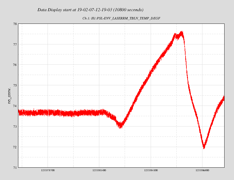
Tweaked the alignment into the reference cavity.  Transmission went from ~1.3 to 4.1.

    whilst I was in the enclosure, the HEPA fans and AC tripped off.  Don't know why.  As a
result it may take the temperature inside the enclosure a while to settle.  The pre-modecleaner
heater drive voltage nearing zero was the tell-tale sign that gave it away.

    Attached is a plot of the room temperature around the time of the mishap.
Images attached to this report
Comments related to this report
rana.adhikari@LIGO.ORG - 17:59, Thursday 07 February 2019 (46860)PSL

is there a new FSS loop measurement to go with this increased cavity power (and increased optical gain)?

rana.adhikari@LIGO.ORG - 18:49, Friday 08 February 2019 (46882)

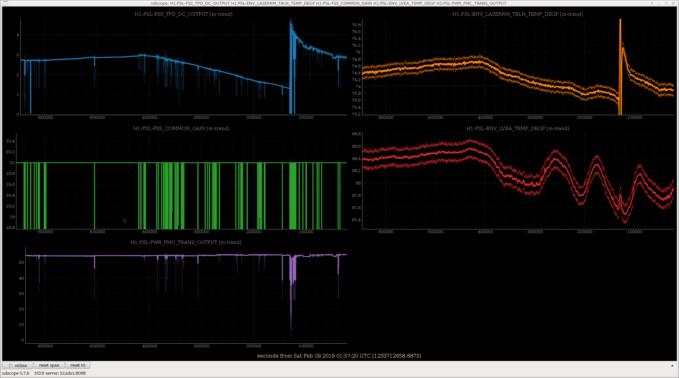
as I suspected, the FSS Common gain has not been adjusted to follow the drifting ref cav transmission, so the FSS UGF has been all over the map. Presumably, the transmitted light, which is used for ALS, is also changing by this large factor.

There is something in the reference cavity optical path which drifts way too much. A 1 degF change in the table temperature is making a 2x change in the cavity power.

You can see that Peter's tweak up happens with the temperature high and so the power degrades again as soon as he leaves the PSL and the temperature changes.

The PMC, on the other hand, has almost no temperature dependence to its transmission.

Options:

  1. Take a couple weeks to diagnose what is wrong with the optical mounts in the refcav path.
  2. Block the beam to the refcav/FSS as LLO and 40m have done.
  3. Redesign the FSS & IMC loops to be stable with 3x gain fluctuations.
Images attached to this comment
H1 SQZ (SQZ)
nutsinee.kijbunchoo@LIGO.ORG - posted 21:13, Tuesday 05 February 2019 - last comment - 15:15, Saturday 09 February 2019(46811)
H1 SQUEEZED!

Sheila, Daniel, Terry, Nutsinee, Craig, Jenne, and others who were cheering in the control room


Today H1 saw (pre-O3) squeeze/anti-squeeze for the first time.

0.9 dB SQZ and 3.3 dB ASQZ at a non linear gain of 2.28.


We used the lowest amount of CLF we could reasonably operate at, 0.05mW into the coupler. 20.5 mW of pump was sent into the coupler on the ISCT6 (this corresponds to ~2.6-2.7 mW hitting the OPO, the nlg wasn't optimized before we injected the squeezing but that's about the best we've seen). We read -15dB of 3MHz demod signal from the Homodyne. The common gain at the LO common mode board was 7dB which gave us a UGF of 10kHz with plenty of gain margin. Boost 1 and 2 on the common path was turned on. 


Sheila has the sqz/asqz plot and the OMC DCPC traces. I have LO phase noise measurement. We will be posting these plot later.

Things we could optimize still is the alignment (which wasn't done at the beginning of the lock acquisition, we did try our best to optimize it while the LO was locked). A single bounce measurement with tonight's alignment should give us a loss estimate. 

Comments related to this report
sheila.dwyer@LIGO.ORG - 01:29, Wednesday 06 February 2019 (46814)

We locked the interferometer in a state that had a lot of DHARD noise, so that we would have a chance to make some measurements with the squeezer.  The DHARD noise is dominating the spectrum below about 300 Hz.  

Some times:

First set of measurements, before Nutsinee pushed the LO loop ugf to about 10 kHz and added the boosts:

  • shot noise reference before injecting squeezing 1:12:14 UTC 6/2/2019
  • squeezing: 1:53:45 UTC  (-0.6dB)
  • anti-squeezing: 2:05:45 (3.6dB)

After the LO loop was set and we made some small alignment tweaks:

  • asqz: 3:38:57 (3.4dB)
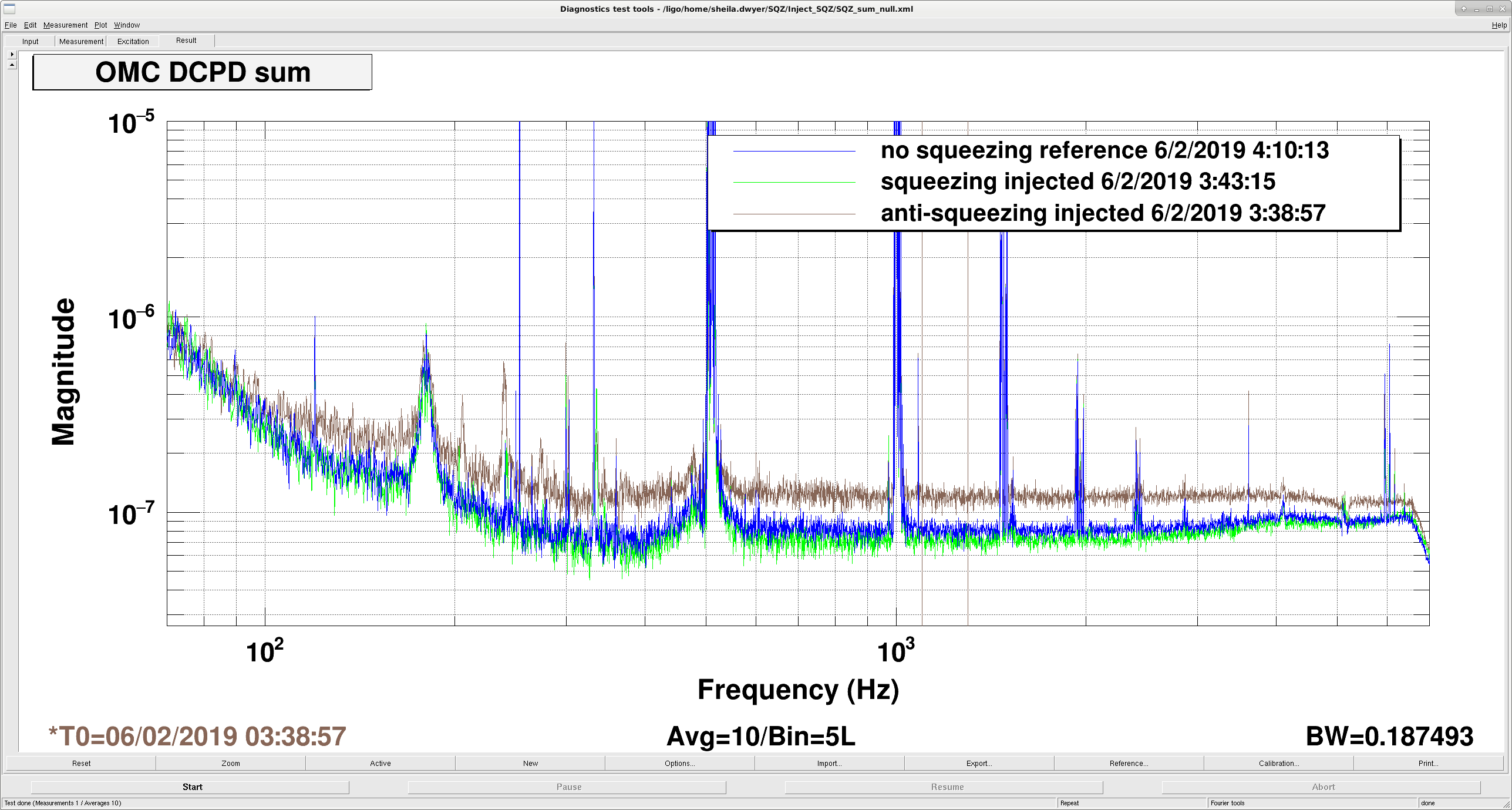
  • sqz:3:43:57 (-0.9dB)
  • reference with no squeezing: 4:10:13

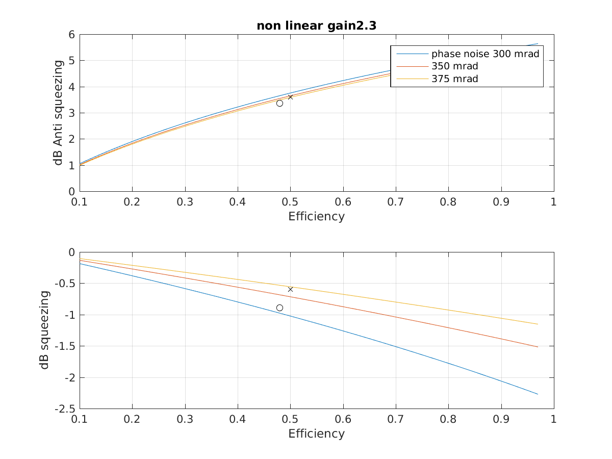
The second attachment shows what these squeezing and anti-squeezing levels roughly mean for a nonlinear gain of 2.3 which is what Nutsinee measured.  This indicates that our total efficency is something around 50%, since we have 19.5% known losses this means that we have almost an additional 40% losses somewhere.  We tried to walk the beam a littel using ZM1+2, but we would like to take some time with the squeezer beam reflected off the SRM and the interferometer unlocked to make sure that we are not close to clipping on anything.  The first measurement taken before Nutsinee adjusted the LO loop implies something between 350-375 mrad of phase noise, after tuning the loop we saw a bit more squeezing but this still implies a large phase noise, something between 300 and 350 mrad.  

Images attached to this comment
lisa.barsotti@LIGO.ORG - 02:20, Wednesday 06 February 2019 (46815)

NICE!!!!!


david.reitze@LIGO.ORG - 10:00, Wednesday 06 February 2019 (46824)

Fantastic!

Nicely done LHO Team!

nutsinee.kijbunchoo@LIGO.ORG - 15:15, Saturday 09 February 2019 (46871)

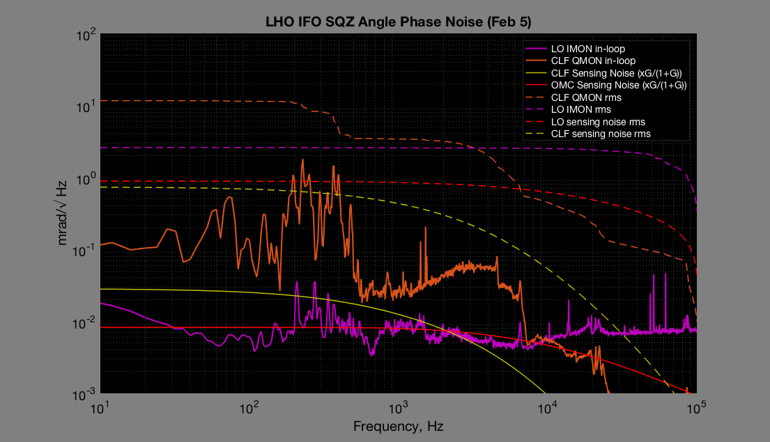
Here's a quick look at the sqz angle phase noise from that night. I haven't had time to add them all up but this plot should give you all the information you need. Right now we believe that LO is mostly seeing CLF noise and its own sensing noise. So the low limit sqz angle phase noise is sqrt(CLF rms^2 + CLF sensing rms^2 + LO sensing rms^2). Look at ~100Hz for example, the low limit of sqz angle phase noise would be sqrt(11.4^2+0.69^2+0.88^2) = 11.5 mrad.

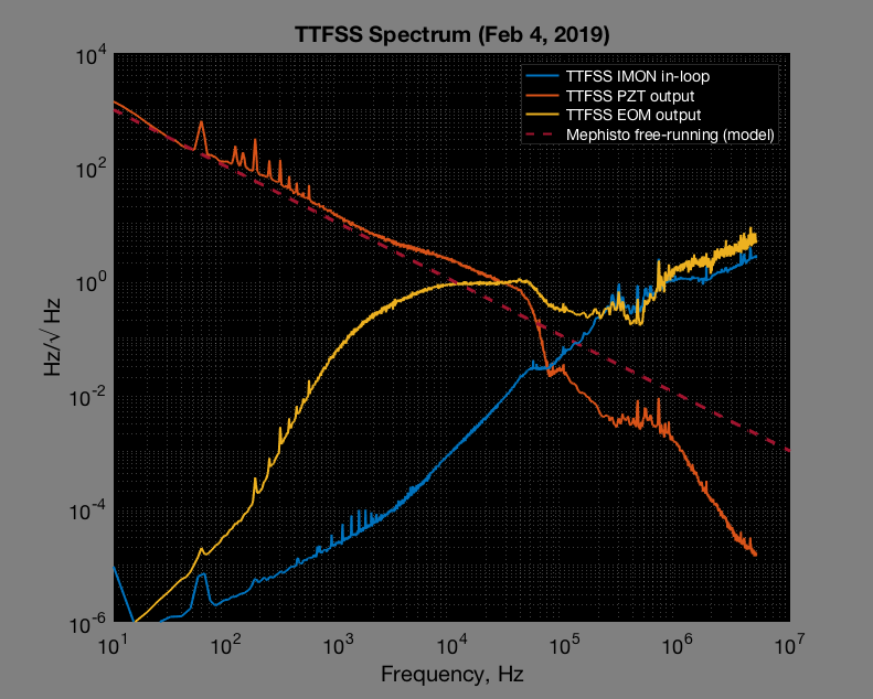
Also attached a very crude plot of an in-loop TTFSS spectrum up to 5 MHz for those who might be interested. Overall noise projection is coming.

*update* The previous TTFSS plot wasn't calibrated properly. I've replaced the plot with a new one that's actually in Hz/sqrt(Hz).

Images attached to this comment
stefan.ballmer@LIGO.ORG - 07:38, Saturday 09 February 2019 (46884)

Awesome!

H1 TCS (ISC, TCS)
aidan.brooks@LIGO.ORG - posted 10:10, Friday 01 February 2019 - last comment - 11:18, Monday 11 February 2019(46738)
Custom CO2 mask for ITMY to counteract point absorber affect on sidebands

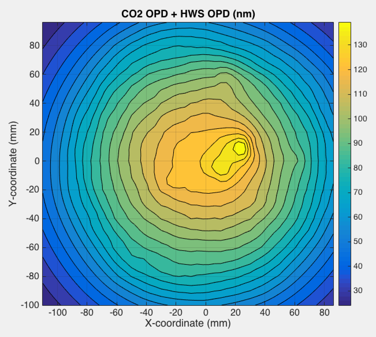
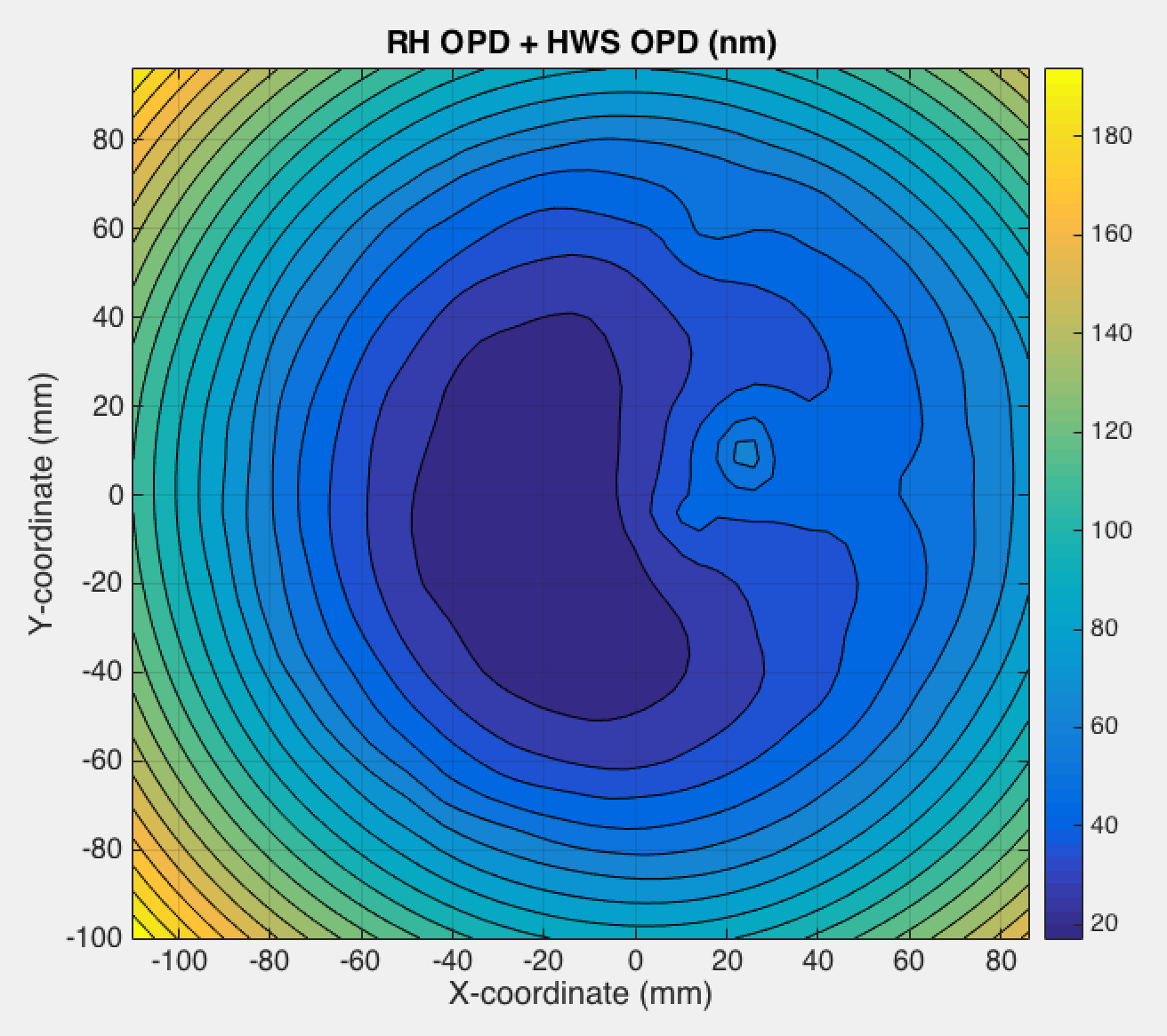
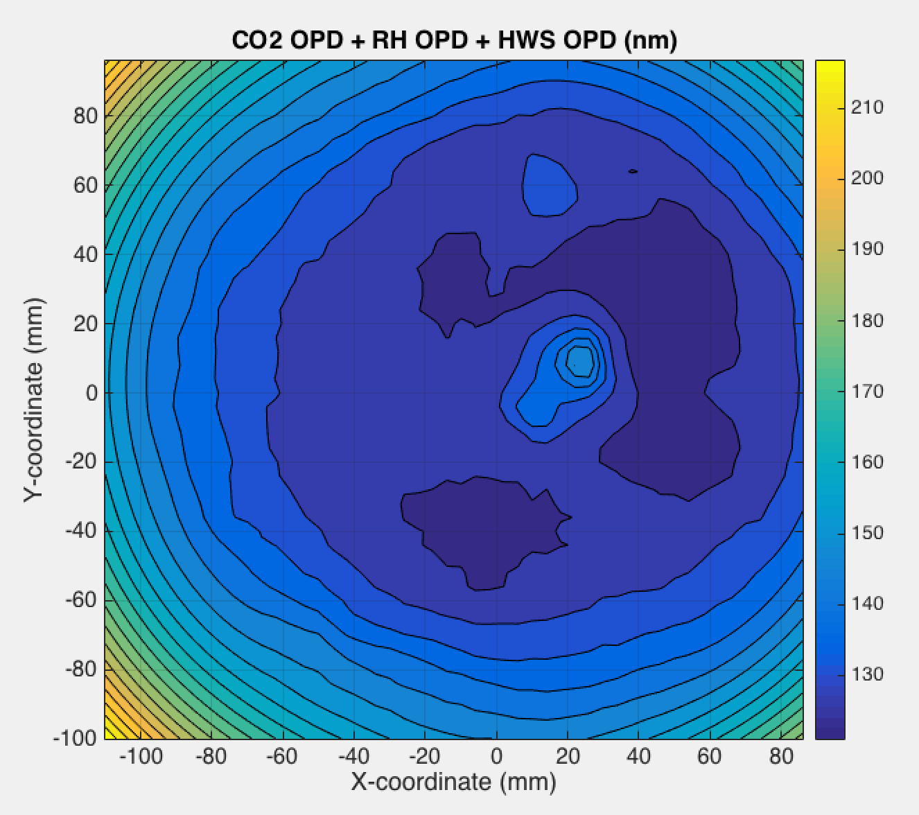
Summary:

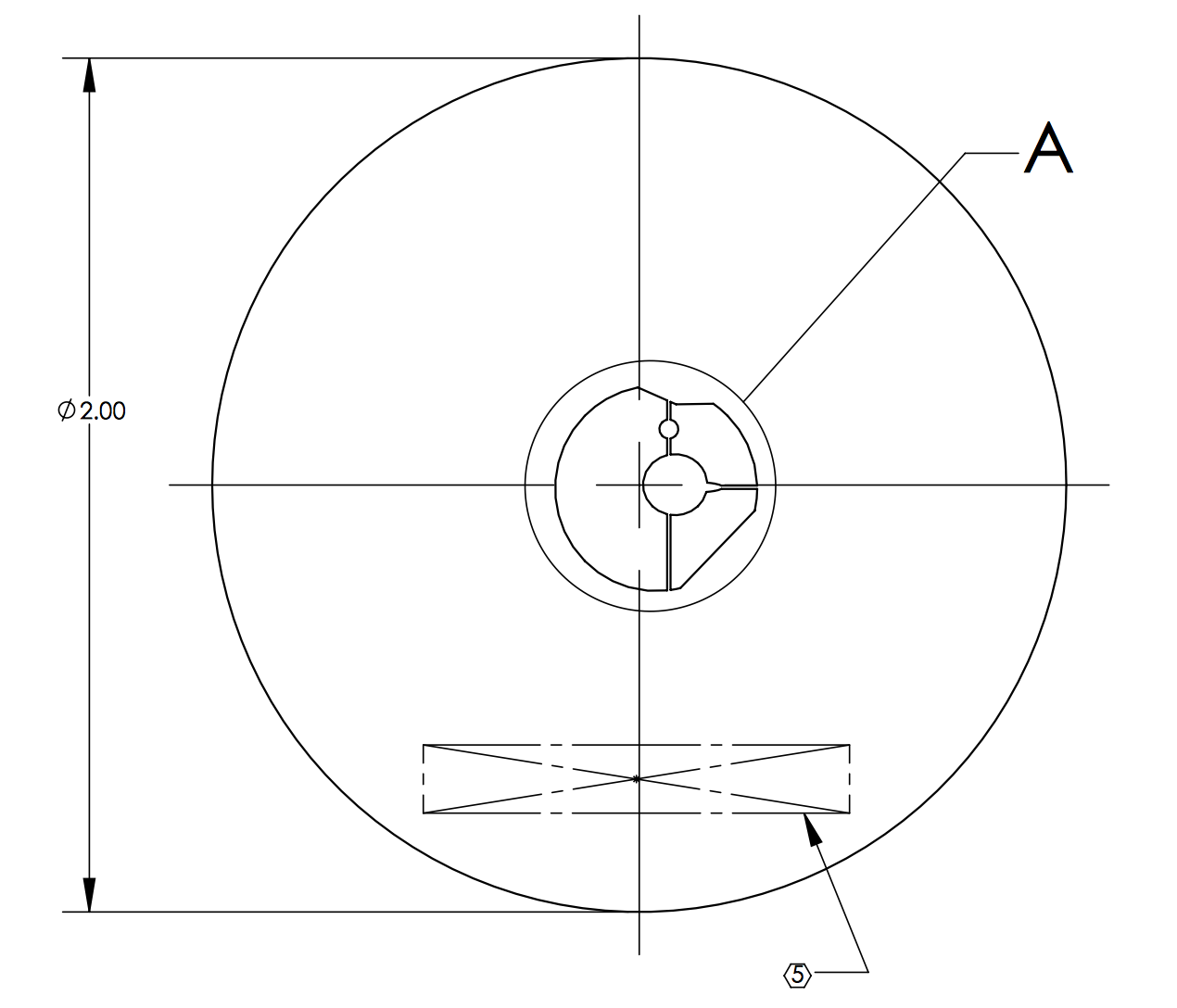
We've designed and ordered a custom mask for the ITMY CO2 projector. The purpose is to counteract the higher-order components of the thermal lenses in the recycling cavities that will predominantly affect the sidebands and lead to higher order differential lensing. Two big questions to be answered:

The installation and alignment of the mask is relatively low overhead. Once aligned, it will remain as an option for the commissioners to explore and further simulations can be performed on expected IFO performance.

Details

The mask is on the DCC at D1900030.

The procedure for finding the optimum mask is as follows:

  1. Work out the steady-state thermal lens from a 4mm diameter, 10mW absorbing region. We're going to use this and rely on the fact that the thermal response is linear: i.e. the sum of the thermal lenses from absorber A and absorber B is the same as the thermal lens from "absorber A + absorberB": TL(A+B) = TL(A) + TL(B).
  2. Create a function of N+1 parameters (we used N=317). For parameter a_i, (where i <= N), we add the above thermal lens centered around a point [x_i, y_i] and scaled by a_i. The N+1 parameter adds a quadratic thermal lens from the ring heater. This function is TL_fit(a).
    1. The points are spaced 10mm apart in rectilinear grid out to a radius of 100mm. Note that in the limit that the spacing is 4mm, we effectively recreate uniform absorption.
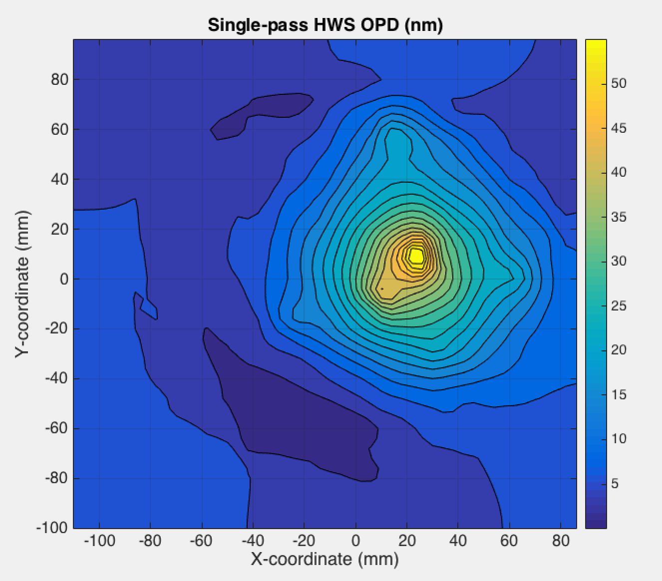
  3. Create the total thermal lens using the data from the HWS (scaled to single-pass) TL_HWS, 
    1. TL_tot = TL_HWS + TL_fit(a)
  4. Create a function that determines the RMS wavefront distortion of this total thermal lens weighted by the intensity of the TEM00 mode on the ITM
    1. = sum(TEM00*TL_tot)/sum(TEM00)
    2. F_RMS(TL_tot) = sqrt( sum(TEM00*(TL_tot - )^2) / sum(TEM00))
  5. Use FMINCON to solve for the values of a that minimize F_RMS. (see aLOG 46127. )
    1. FMINCON allows us to be constraints on the parameters a.
    2. Each of the thermal points was limited to the range [0, 0.1]. The RH was limited 6W of power.
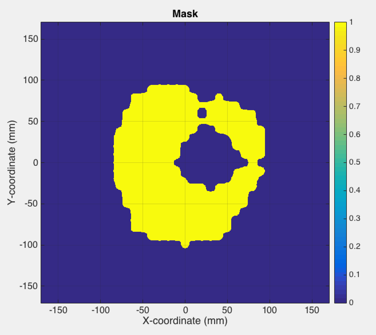
  6. The solution to a yields the required distribution of heat across the test mass. Since we don't want to create a mask that is a regular series of holes (ie. a diffraction grating), we smooth this by a minimal amount to create large shapes of uniform heating and create an image from this. This image is used then used as the basis for a mask. The image is also made 9% larger in the horizontal direction to account for the fact that the AOI between the mask and the CO2 laser beam is 22.5 degrees.

Results from simulation:

Original heat distribution:

Mask for CO2 laser (at ITM scale):


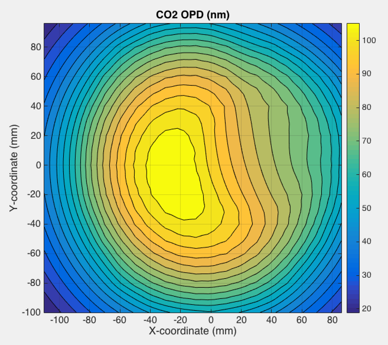
Optical path distortion from CO2 laser projected through mask and imaged into ITM

Optical distortion from CO2 + Self/HWS OPD

OPD from RH + Self/HWS OPD

OPD from CO2 and RH and Self/HWS


Alignment

Alignment is a big issue - clearly this will need to be matched well to the existing thermal lens to be effective. A long term drift in the CO2 laser alignment to the test mass was noticed in Q4 last year (Approximately 12 months after the previous alignment). We need to be cognizant of this.

Fine tuning of the alignment will be accomplished by mounting the mask and flipper mirror on an X-Y translation stage that offers up to 3mm of travel in X and Y (corresponding to 63mm of displacement of the heat pattern in X and Y on the ITM with a magnification of 21x).

Magnification

The mask is set up for the nominal magnification of 21x. We should be cognizant of any variations in the actual magnification as this will create discrepancies between the required and actual heat patterns.

Images attached to this report
Comments related to this report
aidan.brooks@LIGO.ORG - 10:54, Friday 01 February 2019 (46745)

Nominal turn around time for a new mask to be machined and delivered is 5-6 business days (including shipping).

aidan.brooks@LIGO.ORG - 11:18, Monday 11 February 2019 (46888)

Photo of masks.

Images attached to this comment
Displaying reports 43141-43160 of 88637.Go to page Start 2154 2155 2156 2157 2158 2159 2160 2161 2162 End