Displaying reports 43321-43340 of 88618.Go to page Start 2163 2164 2165 2166 2167 2168 2169 2170 2171 End
Reports until 10:58, Tuesday 29 January 2019
H1 CDS
patrick.thomas@LIGO.ORG - posted 10:58, Tuesday 29 January 2019 - last comment - 13:00, Tuesday 29 January 2019(46686)
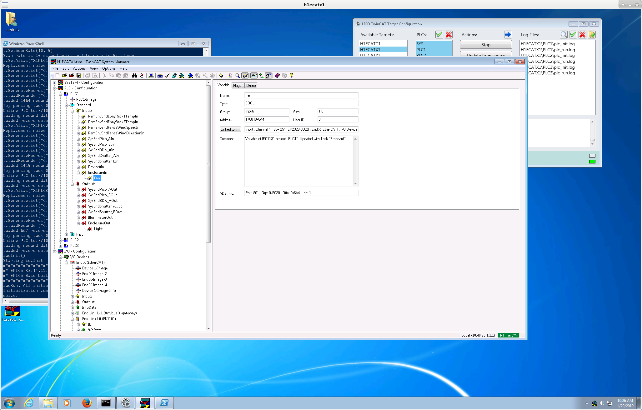
Updated h1ecatx1 to add binary readout of ISCTEX enclosure fan status and control of ISCTEX enclosure light
Patrick, Filiberto

I created a TwinCAT library named Enclosure for the control of table enclosure lights and the readout of table enclosure fans. I added the necessary code to PLC1 for the end stations to handle the fans and lights on ISCTEX and ISCTEY.

Today Filiberto added a EP2328-0002 EtherCAT box after the ALS Laser Table Relay (EP2624-0002) at end X (Box 251 in the first screenshot). I updated the h1ecatx1 system manager to add this box. I linked the readout of the fans to channel 1 of this box, and the control of the lights to channel 3 of the ALS Laser Table Relay box.

I have not run svn update for end Y.

The channel names are:
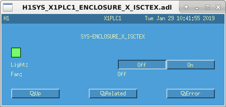
H1:SYS-ENCLOSURE_X_ISCTEX_LIGHT
H1:SYS-ENCLOSURE_X_ISCTEX_FAN

These are set to be in alarm at a value of True.

Filiberto stated that the fans and lights are not yet connected to this box, so these channels are not currently valid.

The autogenerated medm screen can be accessed from SITEMAP -> SYS -> EtherCAT overview -> H1 X1 PLC1 -> Sys -> Enclosure -> X -> Isctex
Images attached to this report
Comments related to this report
filiberto.clara@LIGO.ORG - 13:00, Tuesday 29 January 2019 (46690)

Modified chassis installed is S1400568. Cabling from chassis to table enclosure still need to be pulled, likely next Tuesday.

1. 24V for table enclosure lights
2. 15V TCS
3. Fan Status

H1 CDS
patrick.thomas@LIGO.ORG - posted 08:11, Tuesday 29 January 2019 (46684)
Disabled sensor tests for PCAL laser safety interlocks
Patrick, Richard

WP 8068

Per request, I have disabled the sensor tests for the end X and end Y PCAL laser enclosure interlocks in the TwinSAFE project on h1safety0. These were both channel 7 on boxes 27 and 34. This tripped off the ALS, PCAL, TCS and maybe accidentally the SQZ laser. Richard brought the SQZ laser back on.
H1 ISC (ISC)
georgia.mansell@LIGO.ORG - posted 00:46, Tuesday 29 January 2019 (46682)
power_up_on_rf flag

Georgia, Craig

We had a few fast locklosses from INCREASE_POWER tonight. After taking CARM and IMC OLTFs we realised that the OMC_DCPD_SUM_OUT was going up to 40 mA before we lost lock. We then quickly realised that the power_up_on_RF in LSC params was still true. We have switched this off and reached nominal low noise again.

We had acquired lock just fine with the new low-gain DC centering loops (DC3 pit and DC4 pit). I tried engaging the gentler DHARD pitch cut off (FM4) at NLN but promptly caused a lockloss.

H1 ISC
craig.cahillane@LIGO.ORG - posted 00:27, Tuesday 29 January 2019 (46680)
IMC and CARM OLGs today
Craig, Georgia

We were struggling to increase power all afternoon today.  Georgia and I measured the IMC and CARM OLGs at 2W, and moved the gain sliders a bit to check if they were doing what they should be.  They are.  (Attachment one)

IMC Nominal UGF = 51 kHz
IMC -3 dB on IMC FASTGAIN UGF = 35 kHz
IMC +3 dB on IMC FASTGAIN UGF = 77 kHz

CARM (first) Nominal UGF = 25 kHz
CARM -3 dB on LSC IN1GAIN UGF = 14 kHz

The IMC OLG isn't moving too much on power-up (attach two), but it is down from where it was in November (IMC UGF Nov 2018 = 73 kHz). The CARM OLG is known to fall to around 10 kHz.
There is no problem with the CARM UGF falling below the IMC UGF during power-up, or with the gain slider redistribution, especially since we have powered-up just now.
Non-image files attached to this report
H1 SQZ (SQZ)
nutsinee.kijbunchoo@LIGO.ORG - posted 23:00, Monday 28 January 2019 - last comment - 18:14, Wednesday 30 January 2019(46679)
CLF noise at various power

Daniel, Nutsinee

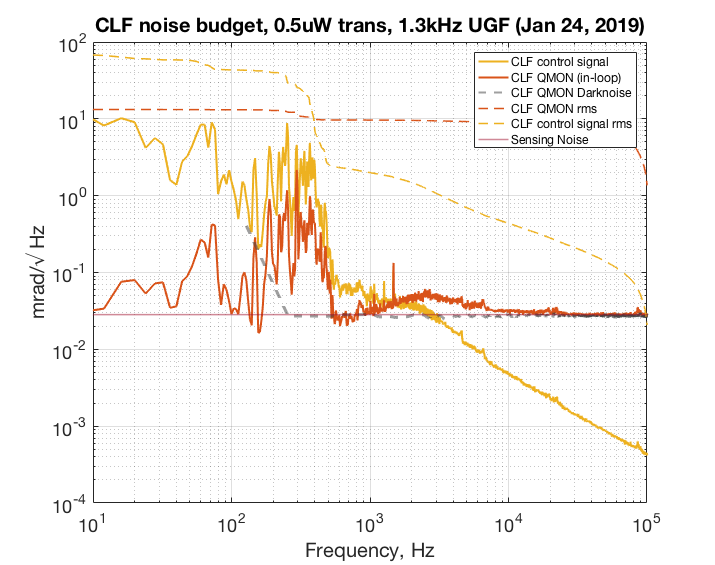
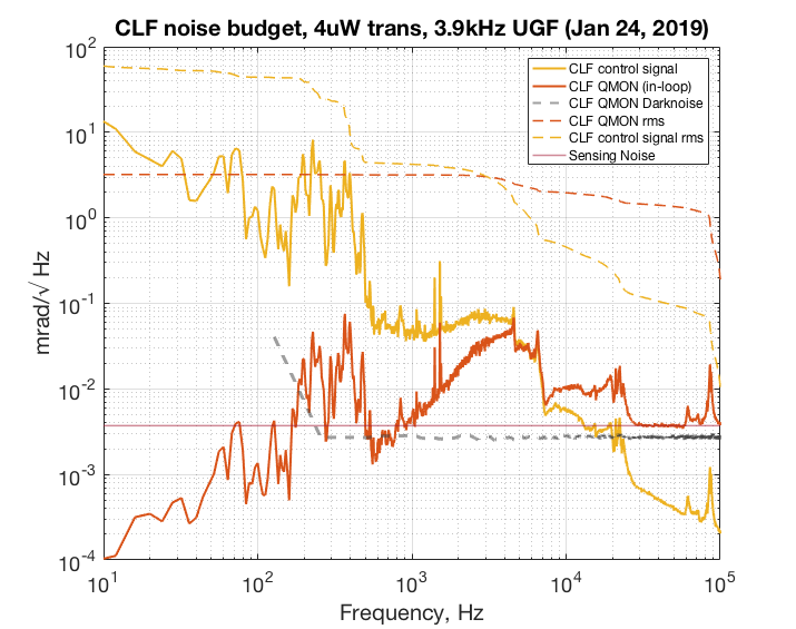
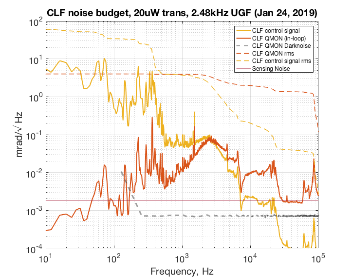
We will later be using this information to calculate the overall phase noise contribution from CLF and what is the best power to operate when injected into the IFO. But for now these plots are just showing noise at various CLF power. At 1X power (0.5 uW CLF transmitted) we are mostly limited by sensing noise. At 10X (4uW transmitted) and 60X (20uW transmitted) power we cleared the sensing noise for the most part. The UGF for 10X and 60X measurement were chosen where the phase margin is ~30deg. The UGF for 1X measurement were chosen simply because we begin to be sensing noise limited right around there. In all case the suppressed CLF signal hangs around 3mrad. 

The RF amplifier (minicircuits ZFL-500LN) was taken out during 60X power measurement. The calibration factor is a bit lower than what we would expected even taken the factor of 25 of the RF amp into account. That part is still unclear why. The manual suggests a gain of ~25 at 3MHz.

The shotnoise was calibrated using a halogen light bulb. By subtracting DN from combined DN SN in quadrature we recover SN which we use to calibrate the RF transimpedance. 


Images attached to this report
Non-image files attached to this report
Comments related to this report
terry.mcrae@LIGO.ORG - 09:24, Tuesday 29 January 2019 (46685)

Just to clarify these CLF noise measurements were taken with the "old" locking scheme, where the OPO is used as the reference (not the PSL reference cavity).

daniel.sigg@LIGO.ORG - 18:14, Wednesday 30 January 2019 (46712)

Errata: The shown uW are half of the actual uW.

Not surprisingly, the forest below 1 kHz is due to acoustic couplings (most likely to the fiber). The attached plot shows the coherence between the CLF controls signal and the accelerometer on ISCT6. The noise above 1 kHz is still a mystery.

Non-image files attached to this comment
H1 ISC
sheila.dwyer@LIGO.ORG - posted 20:42, Monday 28 January 2019 - last comment - 20:42, Monday 28 January 2019(46676)
centering loops cross coupling with DHARD P were making the loop less stable

Jenne, Sheila, Marie, Arnaud, Danny, Georgia, Craig

DHARD P investigation:

This morning we did a few things to investigate the problems we have been having with DHARD (see 46663 for links to relevant alogs).  We haven't found the cause of the positive phase shift at 1 Hz, but we have found that a cross coupling with darm is reducing the gain of the DHARD loop.  

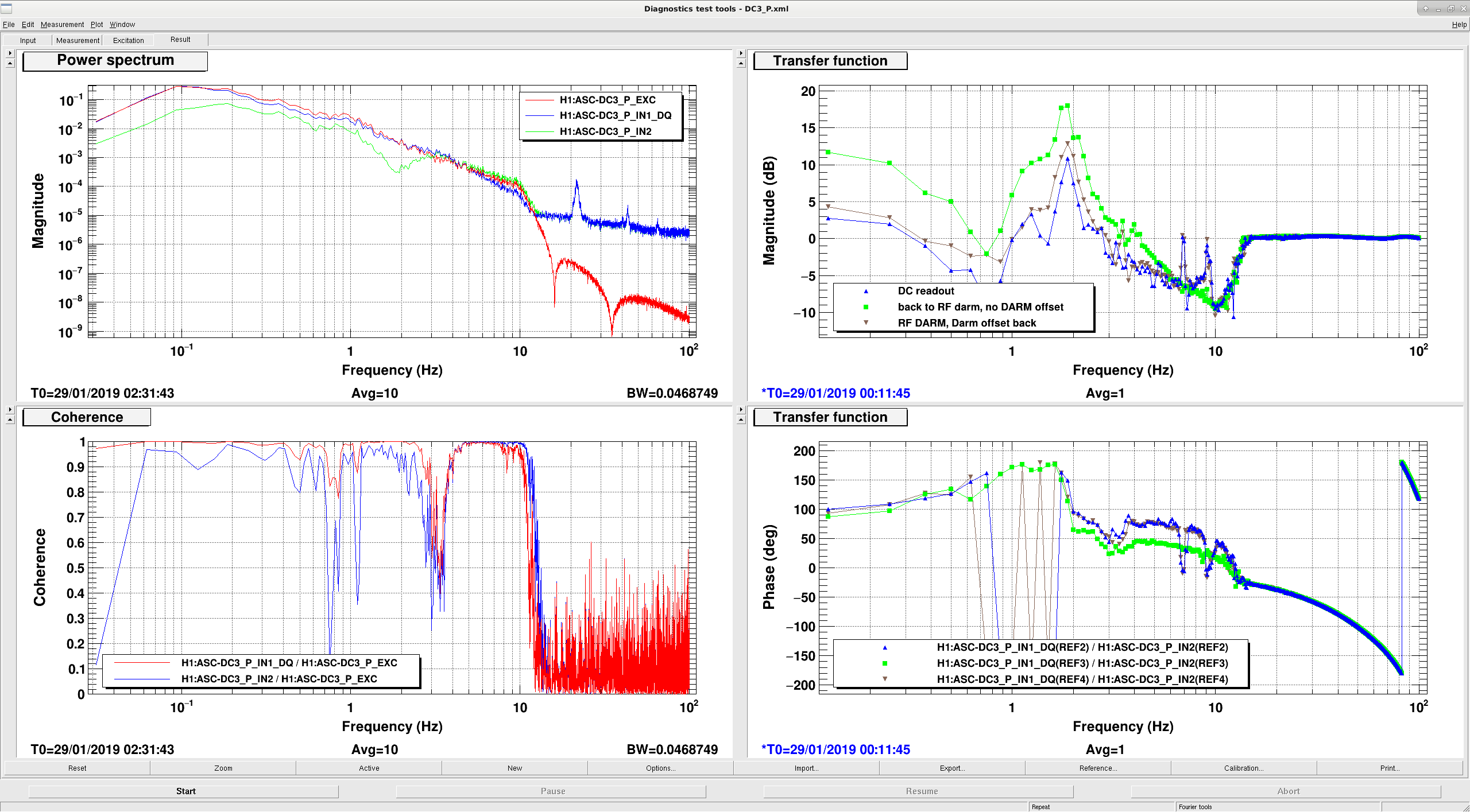
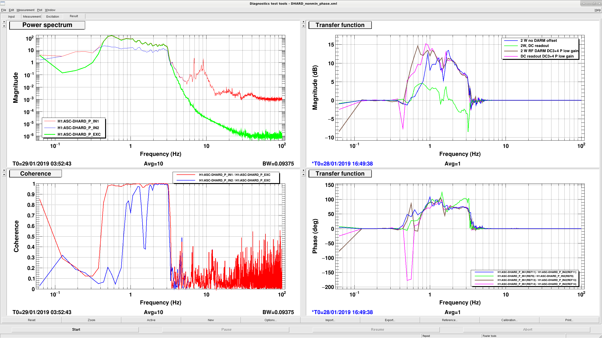
When I got here Jenne had the interferometer locked at 1.8W input power, and we made a series of DHARD P measurements at different configurations.  We found that there is a change in the DHARD P gain when the DARM sensor is changed from AS45 to the DCPDs, this isn't due to the DARM offset but is actually a result of changing the DARM sensor (see attached screenshot).  We tried changing the gain of CHARD P by 30dB, no impact. We also tried turning off the dither loops, and running the A2L decoupling script (more on that below), but this didn't change the DHARD transfer function. 

At 2W input power we don't see the strange phase behavior at 1 Hz, but when we power up to 10W we do see it, locked on RF DARM or DC readout.  (see attachment).  However, on RF DARM the loop remains stable because we are not close to having a unity gain crossing at 1Hz. 

DC centering:

We also looked at the DC3_P centering loop, which centers onto AS_A the WFS used for DHARD. The gain of the centering loop depends on the DARM offset, as can be seen in our third attachment. We then measured the gain of the DHARD P loop for different centering loop configurations, and found that the centering loops are reducing the gain of the DHARD loop.  This coupling from centering to DHARD depends on the DARM offset, since the DARM offset means that there is a signal in 45Q on all quadrants of the WFS head. We took a few minutes in DRMI to change the filters in the DC centering loops for pitch, so that our UGFs are now about 0.25 Hz.  We haven't done this for the yaw loops yet, but we probably need to. 

With the reduced gain in the centering loops, we were able to transition to DC readout and not see a change in the DHARD loop shape, shown in the third attached screenshot.  We added a 0.8 Hz pole, a low pass at 1.5 Hz, and a -10dB filter to DC3+4 pitch, we ran these with a gain of -0.25 for the measurement where transitioning to DC readout didn't change the loop shape.  We have now reverted to the old loops because we are not able to power up, but it seems that the problem with powering up is unrelated to the centering loop change since we still can't power up.  

A2L script working  again:

We had tried to run the A2L decoupling script on Friday, but ran into a problem with nds.  Over the weekend Jonathan Hanks found a fix for us, which we can run this way:

PYTHONPATH=/ligo/home/jonathan.hanks/nds2-client-bugfix/lib/python2.7/site-packages
export PYTHONPATH

userapps/isc/h1/scripts/run_al_a2l.py

Suspension checks:

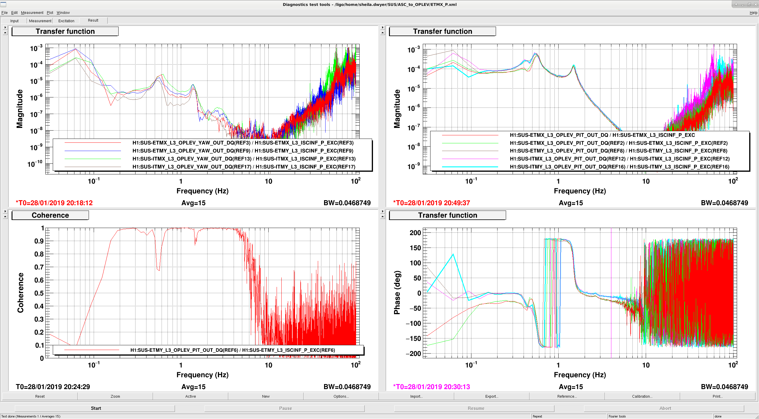
This morning Marie Arnaud and Jenne checked that all 4 of the PUM coils are moving the test masses on ITMX, ITMY and ETMY, which they are. Still have to check ETMX but seems fine regarding the measurements below. 

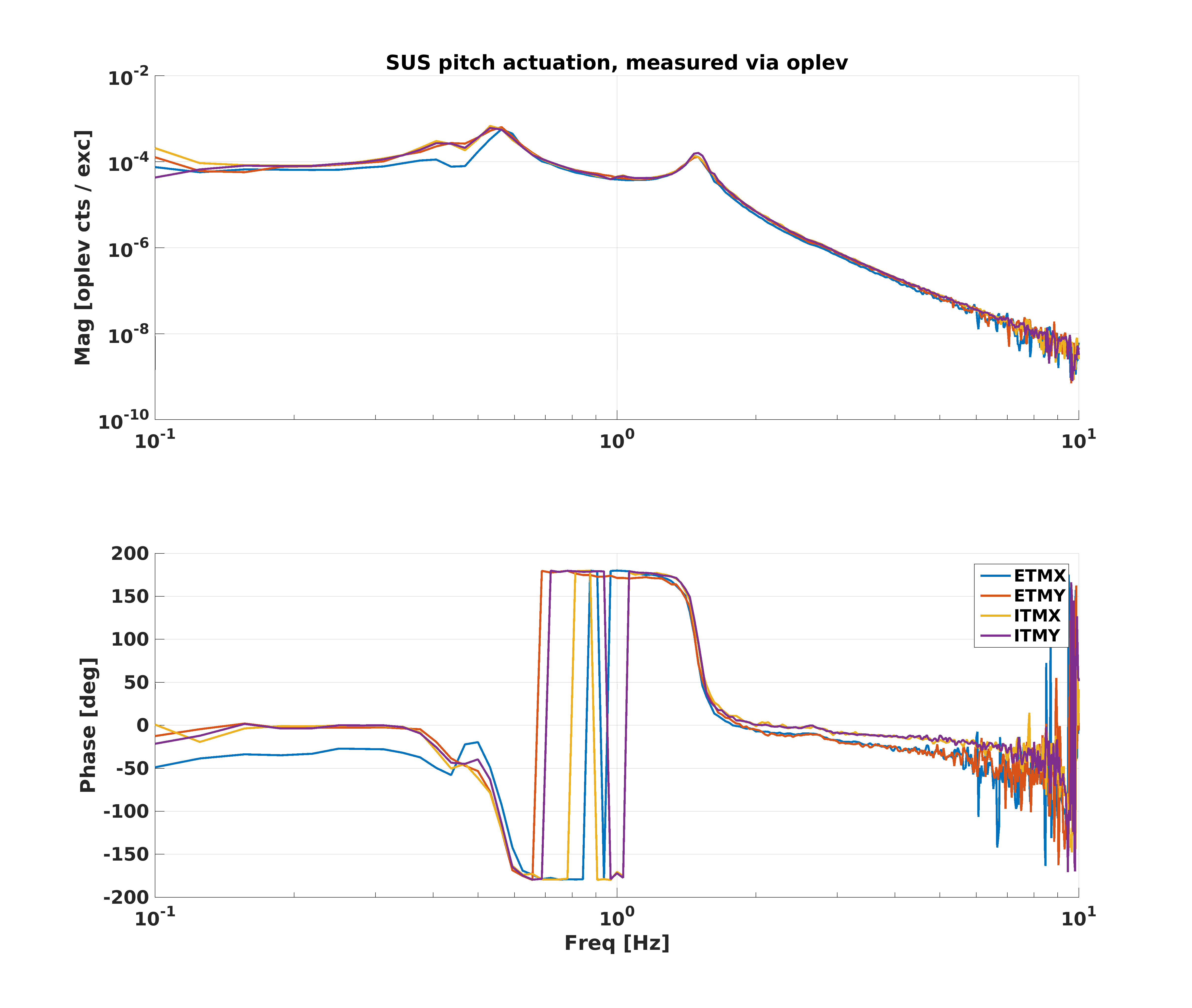
We also measured the transfer functions from the ASC input for pitch on each suspension to the optical lever, with the suspension set up to drive the PUM and the test mass as it is when we are locking.  The second attached screenshot shows the measurements, they are mostly the same with no large P2Y coupling on any of the test masses.  There is a difference in the measured phases between the ETMs and ITMs, which is 16 degrees at 4Hz.  We looked for settings that are different between the ITMs and the ETMs: There is a bounce roll filter that is in the top mass offloading path for the ETMs but not the ITMs, and there is an additional (narrow) 28Hz notch in the ITMs compared to the ETMs.  We tried retaking the measurements without these differences, they didn't matter for the measured TF as expected.The data is attached, Jenne is combining them offline.  

Images attached to this report
Non-image files attached to this report
Comments related to this report
jenne.driggers@LIGO.ORG - 19:07, Monday 28 January 2019 (46678)

In the attached figures, I show the TFs measured this morning by actuating the suspension and watching the oplevs (SUSactuators), as well as what happens if I naively combine those 4 suspension measurements with our standard output matrix for DHARD (Standard_DHARD_outmtrx) to get the DHARD plant (magnitude is arbitrary here). 

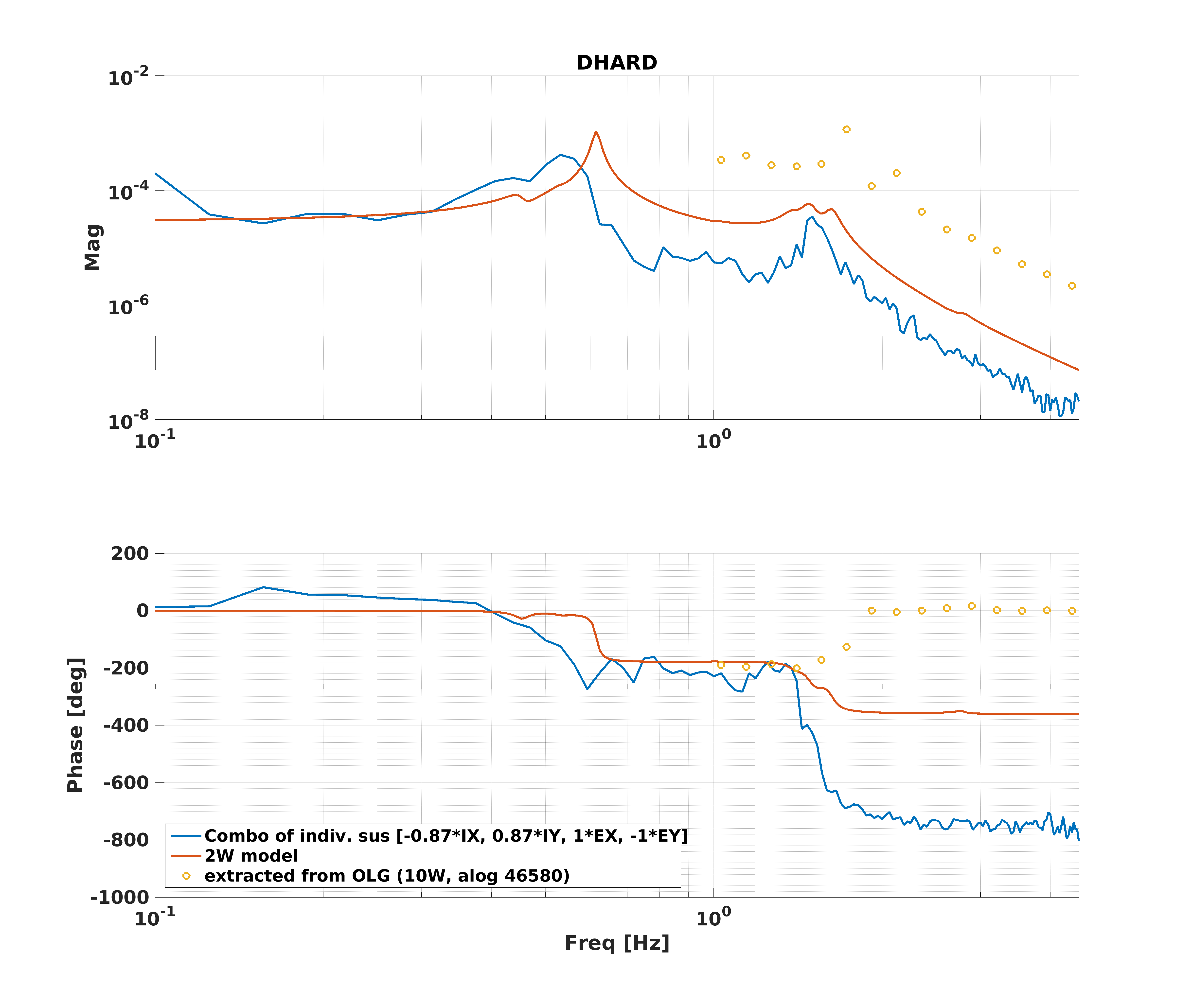
In this second figure, I compare the DHARD plant from combining the 4 individual TFs (which do not have radiation pressure effects, since the IFO was unlocked), the 2W DHARD modeled plant (which is basically identical to a 0W plant, since there is so little circulating power), and the DHARD plant extracted from an OLG measurement last week (alog 46580). I think that we need to revisit our relative suspension actuation strengths, so that they match up more precisely.  I don't totally understand why the plant from the combination of individual suspensions seems to have extra phase lag above 1.5Hz, but it certainly shouldn't be like that.  If I hand tweak the output matrix and look at the resulting DHARD plant from the combined suspensions, I can make all kinds of weird phases, or I can make them look sensible. 
So, it seems like our actuation matrix is some combination of HARD and SOFT, common and differential, and this is contributing to the cross-coupling and weird phase.  However, I'm not sure if this story hangs together though with Sheila's finding that the gain of the DC centering loop affects the DHARD OLG.  Certainly it couldn't hurt to check that our HARD and SOFT actuations are as orthogonal as possible.
Images attached to this comment
H1 CDS (CDS, PEM)
patrick.thomas@LIGO.ORG - posted 12:48, Monday 28 January 2019 - last comment - 13:01, Monday 28 January 2019(46674)
Corner weather station serial communication failed
It appears that the serial communication to the corner weather station failed on Jan. 22 2019 at around 20:14:42 UTC. The readbacks have been invalid since.
Non-image files attached to this report
Comments related to this report
patrick.thomas@LIGO.ORG - 13:01, Monday 28 January 2019 (46675)
Powercycling the weather station (in the MSR) appears to have brought it back.
H1 PSL
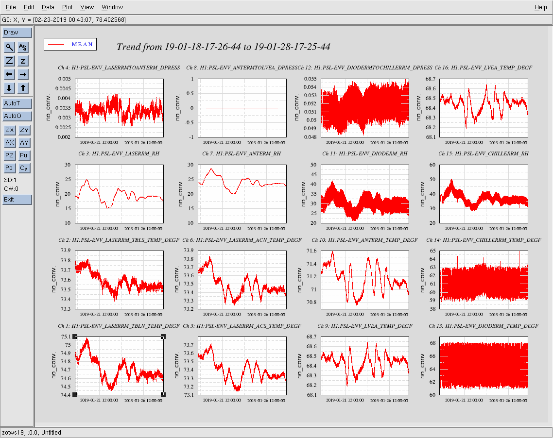
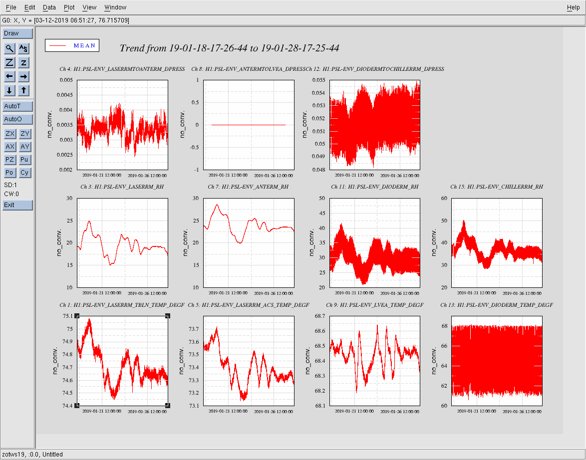
edmond.merilh@LIGO.ORG - posted 10:02, Monday 28 January 2019 (46673)
PSL Weekly Report - 10 Day Trends FAMIS #10594

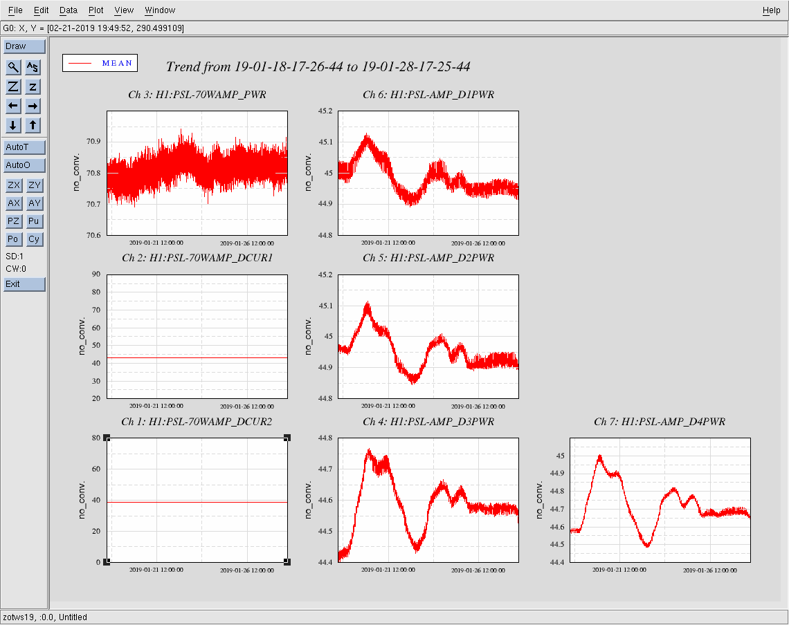
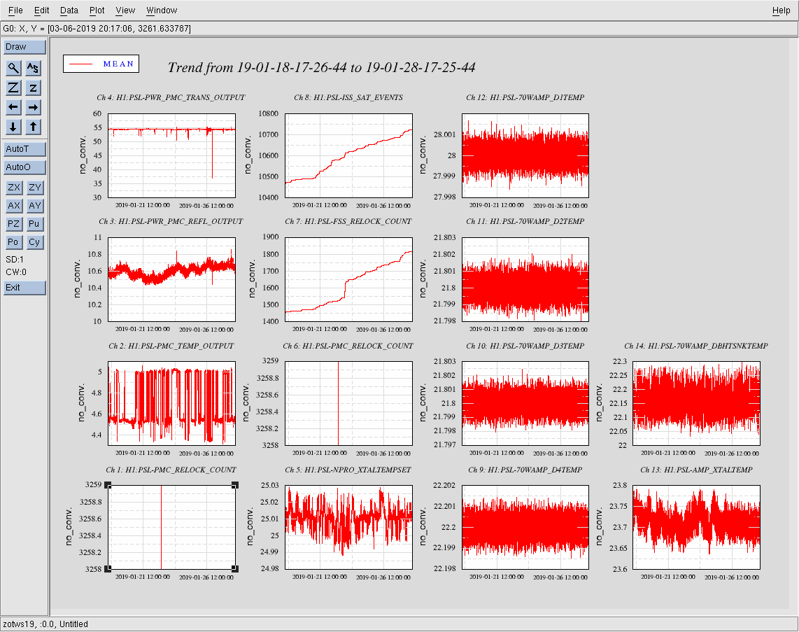
All trends look nominally ok. PMC trans could use some tweaking.

Images attached to this report
H1 AOS (SUS)
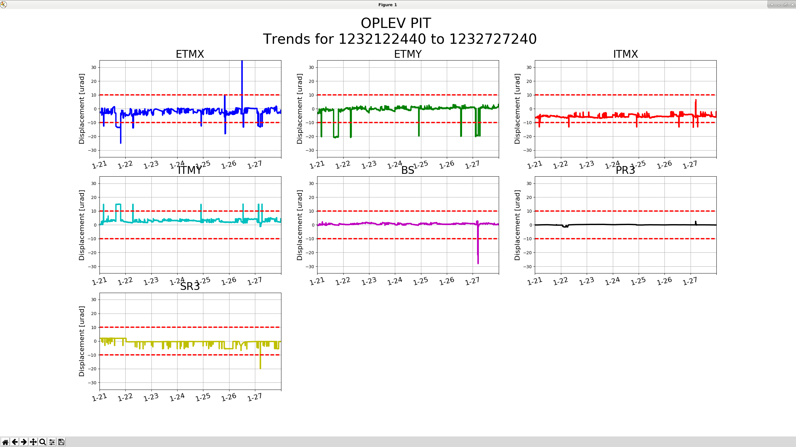
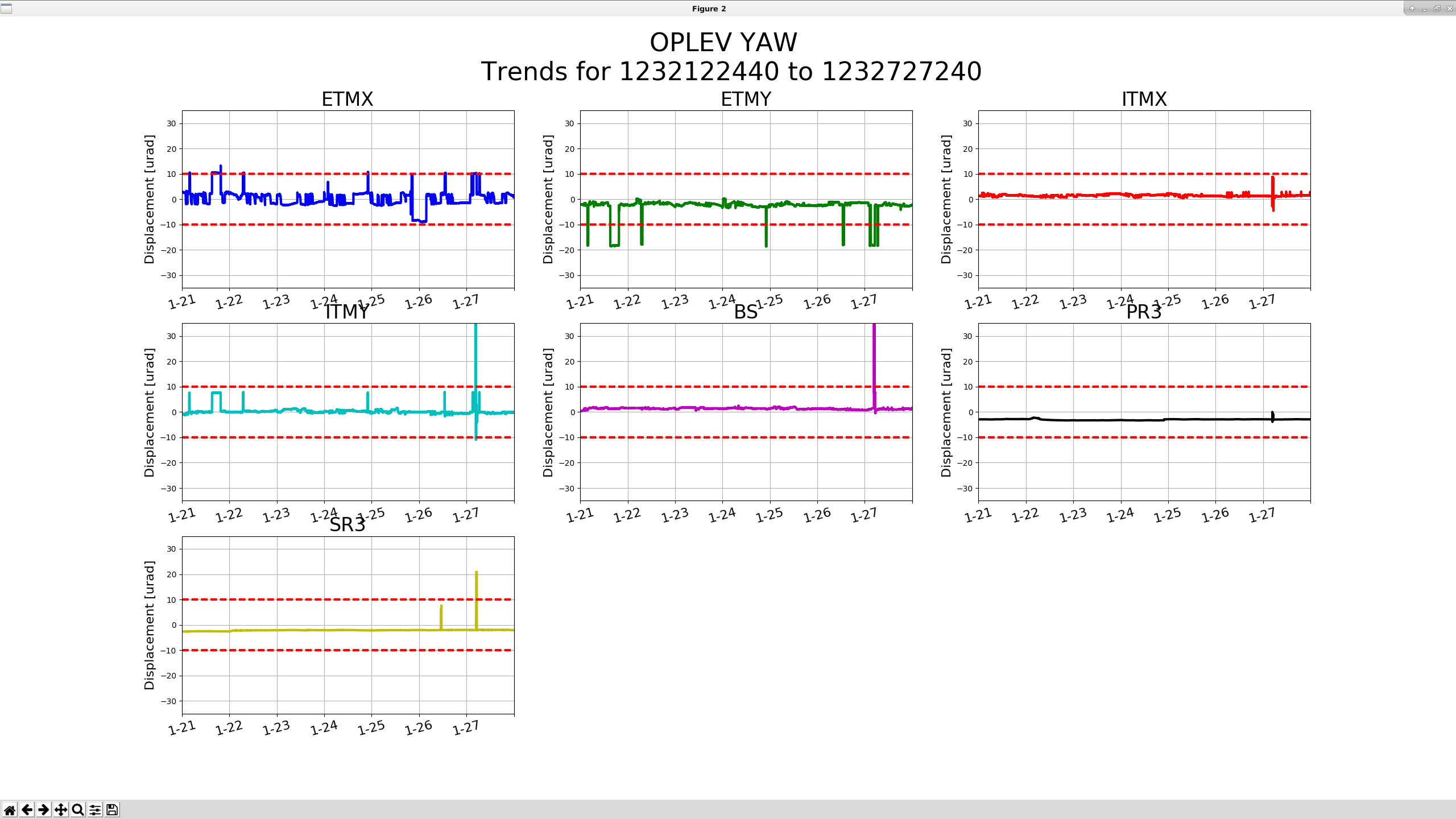
jim.warner@LIGO.ORG - posted 09:25, Monday 28 January 2019 (46671)
Optical Lever 7 Day Trends

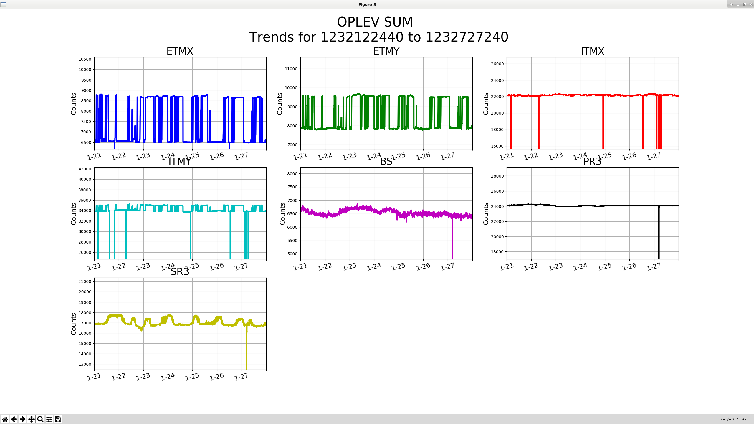
All oplevs seem to have reasonable sums and are roughly in the middle of their ranges, seems ok.

Images attached to this report
H1 PSL
jim.warner@LIGO.ORG - posted 09:12, Monday 28 January 2019 (46670)
PSL Weekly

Laser Status:
Front End Power is 32.25W (should be around 30 W)
70W Output Power is 71.1W
Front End Watch is GREEN
70W Watch is GREEN

PMC:
It has been locked 5 days, 18 hr 17 minutes (should be days/weeks)
Reflected power = 10.65Watts
Transmitted power = 54.35Watts
PowerSum = 64.99Watts.

FSS:
It has been locked for 0 days 2 hr and 43 min (should be days/weeks)
TPD[V] = 3.271V (min 0.9V)

ISS:
The diffracted power is around 2.4%
Last saturation event was 0 days 4 hours and 28 minutes ago (should be days/weeks)


Possible Issues:
 

H1 TCS (TCS)
corey.gray@LIGO.ORG - posted 08:37, Monday 28 January 2019 (46669)
TCS Chillers FAMIS Task (#11476)

Addressed TCS Chillers (08:05 - 08:10 AM PST today)

H1 ISC (SQZ)
koji.arai@LIGO.ORG - posted 02:52, Monday 28 January 2019 - last comment - 16:56, Monday 28 January 2019(46667)
H1 OMC HOM/SB resonant structure (and possible mitigation of 9th-order 9MHz SB resonance)

The HOM/SB resonance of the current H1 OMC was recalculated with refined analysis.

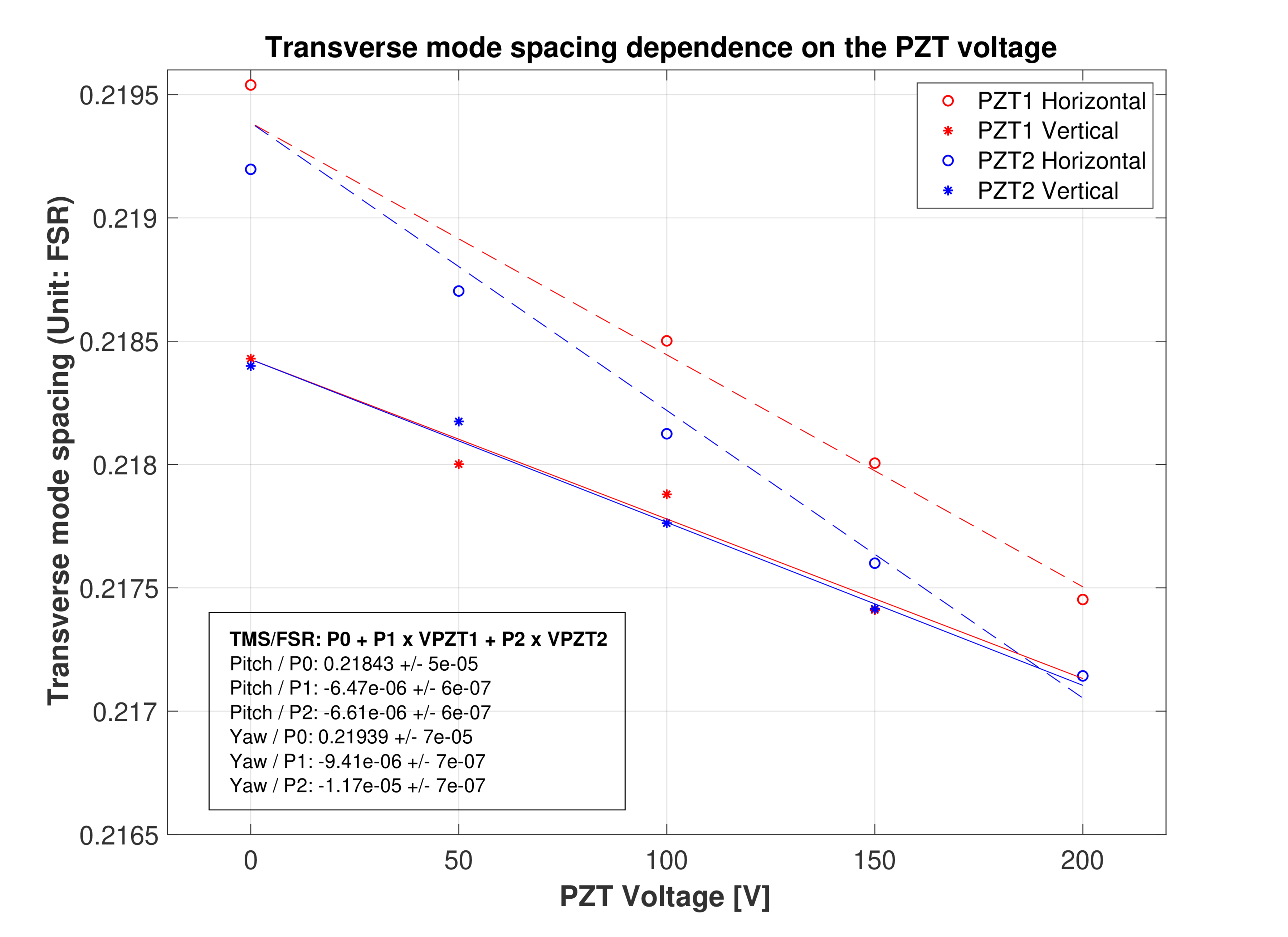
Attachment 1 shows how the transverse mode spacing (TMS) depends on the PZT voltages. Note that the vertical axis is the ratio of TMS and FSR. PZT2 is the nominal OMC actuator for locking and PZT1 is currently used for the OMC shutter.

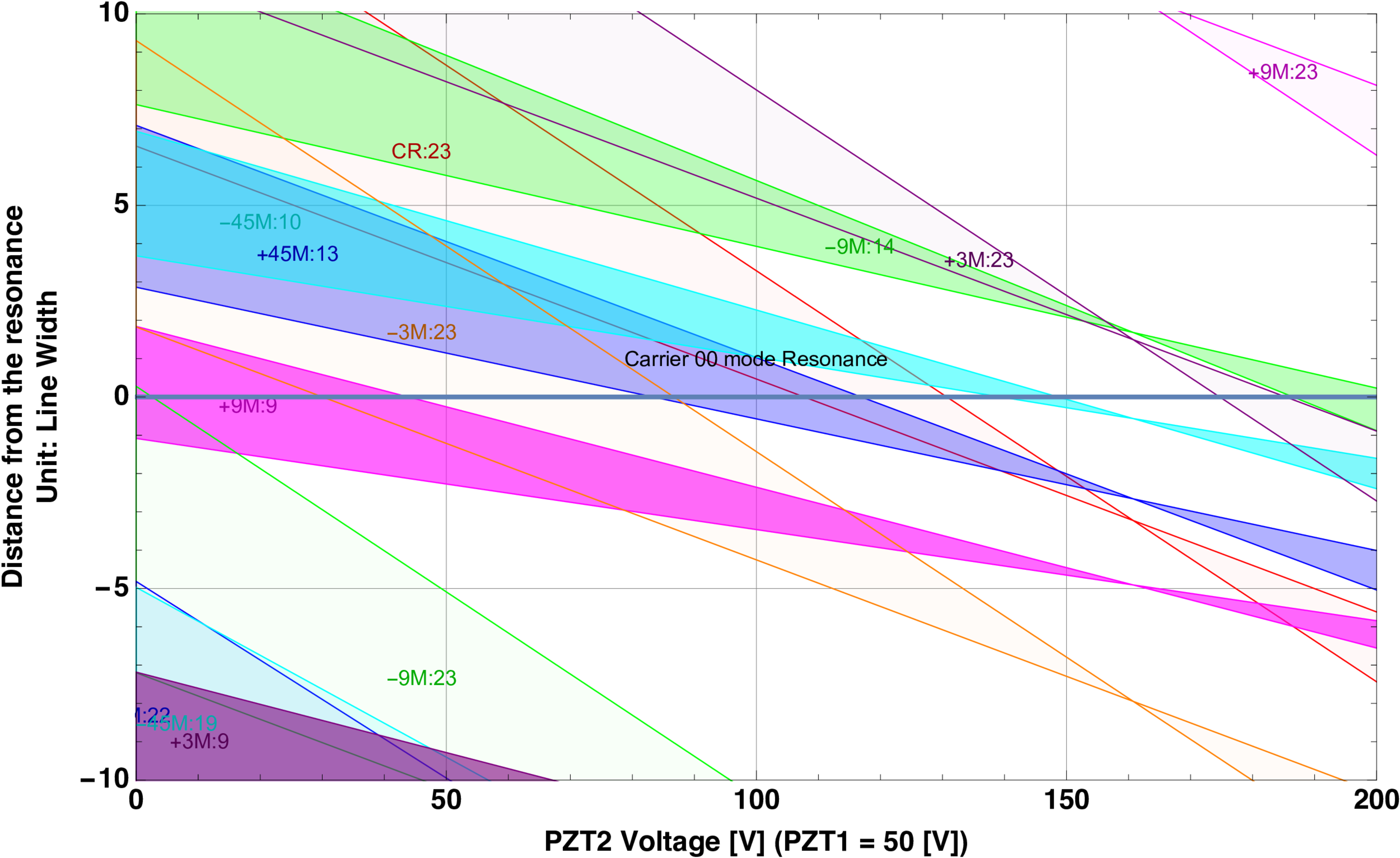
Attachment 2 shows the higher-order mode and sideband resonances that comes close to the carrier resonance. The calculation inludes up to 24th order HOMs. As per Sheila's suggestion, I have added the modes for CLF (+3.125123MHz and -3.125123MHz).

Over the entire range of the PZT (0~100V) , the 9th-order 9MHz upper sidebands is coincide with the carrier TEM00 resonance. The 23rd-order 9MHz lower sidebands ("-9MHz:23") and the 23rd order 3MHz lower sidebands ("-3MHz:23") are also resonant but probably it is not the primary issue. Otherwise, the CLF modes does not come into the TEM00 resonance.

So, in order to avoid the 9th-9MHz, we want to go to higher PZT2 voltage, but we limit the voltage to 100V to avoid possible "sudden death" of the PZT, which L1 OMC had.

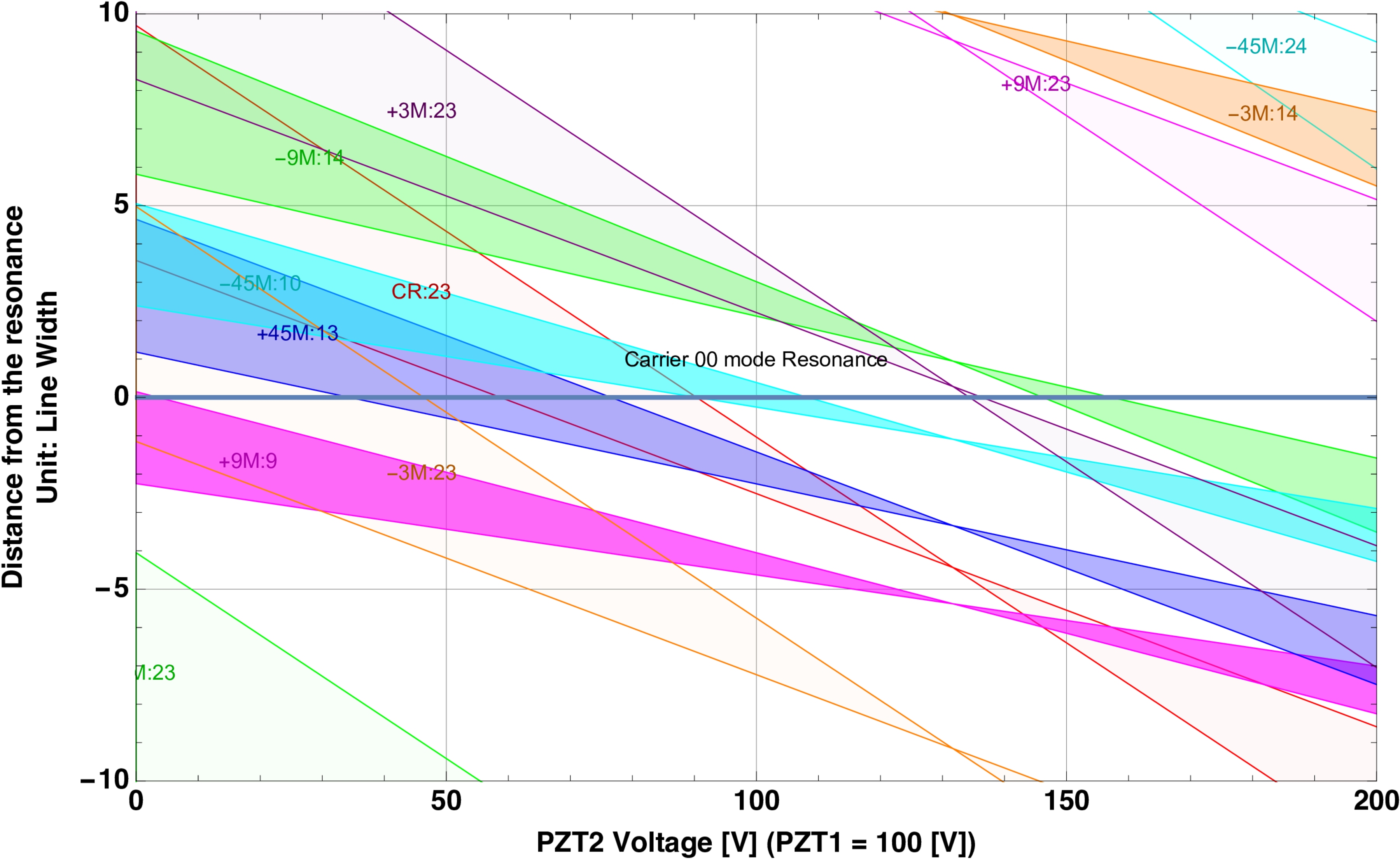
Another possibility is to apply some voltage (<100V) to PZT1. This way, we can shift the structure to the left side. The results with PZT1=50V and 100V are shown in Attachments 3 and 4. This makes the 45MHz sidebans come into play but they are 13th order and 10th order. Considering the RIN of 45MHz sidebands is lower than the 9MHz one, this would help to improve the SB RIN coupling?

To allow this high but constant voltage application to PZT1, we need to modify the PZT driver circuit.

Images attached to this report
Comments related to this report
daniel.sigg@LIGO.ORG - 09:43, Monday 28 January 2019 (46672)

The CLF frequency is ±3.125000 MHz sharp.

koji.arai@LIGO.ORG - 16:56, Monday 28 January 2019 (46677)

I got 3.125123MHz from Sheila. But no worry. The 123Hz difference just vertically shifts the plot by less than 10^-6. It is insignificant.

H1 ISC (ISC)
georgia.mansell@LIGO.ORG - posted 01:35, Saturday 26 January 2019 - last comment - 00:26, Tuesday 29 January 2019(46653)
Locking tonight - moving dither lines back, ASC still not optimal, EX glitches

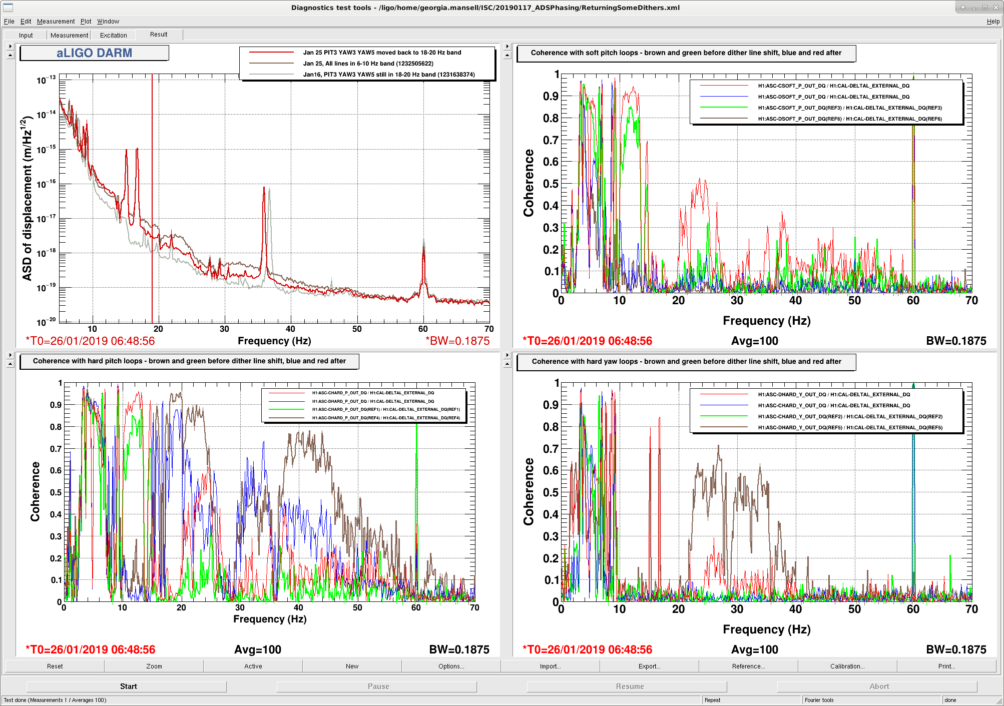
For most of the week we have had extra broadband noise in DARM, in the 10-50 Hz region, coherent with our ASC signals. The obvious difference between last week and this week is on Sunday I moved three of the alignment dither lines to low frequency. Today Sheila and I moved those lines (PIT3 YAW3 and YAW5) back to their 20 Hz frequencies. This reduced, but did not eliminate, the extra noise in DARM and the coherence with the hard loops.

In the attached spectra the top left is DARM, brown is early this evening with the dithers all in the 6-10 Hz band and red is after returning PIT3, YAW3 and YAW5 back to the 18-20Hz band. Grey is a reference from Jan16, when the dither loops were in the same configuration as the red trace, but the noise was lower. The other plots show coherence with the ASC loops (Hard pitch and yaw on the bottom left and right, soft on top right [we are not using the soft yaw loops at the moment]). Brown and green references are from today when all the dithers were in the 6-10Hz band; red and blue are from after the three dithers were moved back to the 18-20 Hz band, and the loops allowed to re-converge. The hard loop coherence with darm was reduced, most noticably in the 35-60Hz region for DHARD P, and 25-40Hz refion for DHARD Y. The soft loop coherence got worse with the new dithers.

We're not sure why the A2L decoupling is worse with the lower frequency dithers. There is certainly cross-coupling between the loops.

I've reverted to the 18-20Hz dither lines for PIT3 YAW3 and YAW5 in the guardian, but weekend commissioners may have to proceed through ENGAGE_SOFT_LOOPS (and CHARD_BLEND and LOWNOISE_ASC) with caution. I've left the gains pretty low so it might take too long for things to converge. I tried testing out lock requisition tonight but we've had an earthquake that has made things a bit tricky.

Another warning to tomorrow's commissioners tonight in ENGAGE_SOFT_LOOKS CSOFT P, the dithers, INP1 and SCR1 all rang up at once and unclear if the cause was the earthquake, or something else. We later had a lockloss in CHARD_BLEND that looked like chard pitch was responsible...


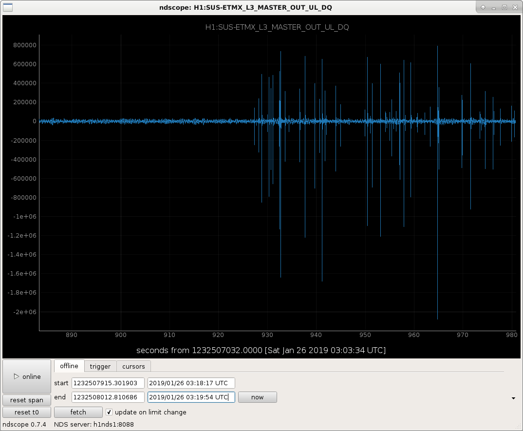
Another thing to note during this evening's lock: We had period of continuous glitching of EX ESD, maybe a bad glitch caused other glitches? EX L3 saturated for a few minutes with many glitches from 03:15:57 - 03:24:12 UTC (Jan 26). Second attachment is a screenshot of the time seri

Images attached to this report
Comments related to this report
georgia.mansell@LIGO.ORG - 00:26, Tuesday 29 January 2019 (46681)

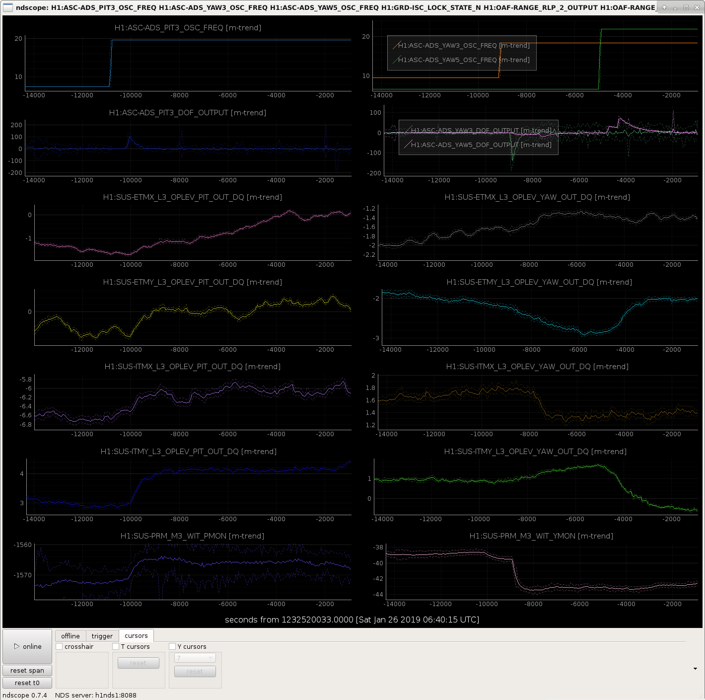
Keita suggested I look at the op lev trends while we were shifting the dither line frequencies, to see how much the test mass pointing changed over the course of the lock. First attachment shows dither frequencies, and outputs of the dither loops, test mass op-levs, and PRM witness sensor. When turning PIT3 and YAW3 on at the new dither frequency, ITMY pointing changes by ~1 urad, and PRM changes by a few counts. When YAW5 convergest with the new dither frequency, ITMY and ETMY have both moved by roughly 1urad.

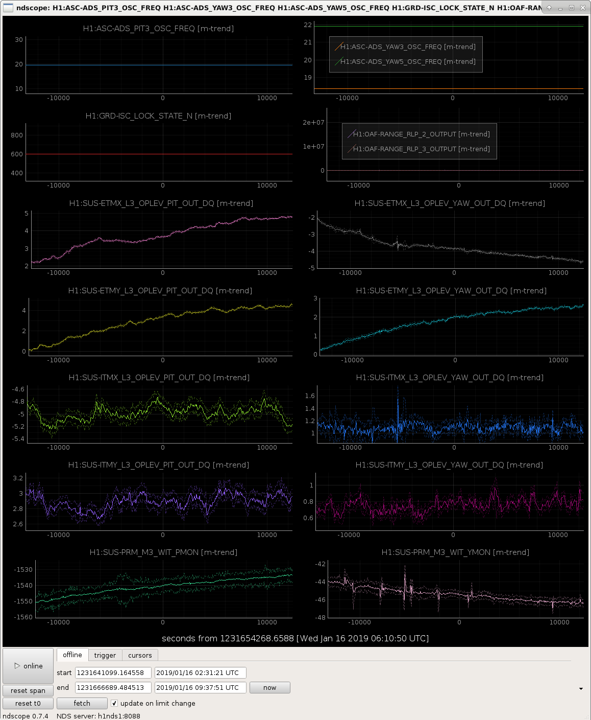
I was initially concerned by this shift in pointing, but I had a look at the op levs over the course of a long lock earlier this month and it seems that we see much larger excursions over the course of a normal lock (second attachment).

Images attached to this comment
H1 ISC (Lockloss)
jonathan.richardson@LIGO.ORG - posted 14:48, Friday 25 January 2019 - last comment - 17:51, Thursday 31 January 2019(46642)
Is dynamic range of ETMX ESD a source of glitching?

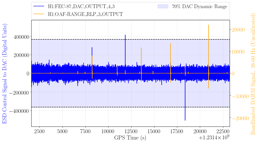
I've examined the time series of the control signal to the ETMX ESD, which is being used alone to control the DARM degree of freedom. There is some evidence the dynamic range might be too small. Every time the ESD control signal nears the end of its dynamic range (+/-2^19), an IFO glitch occurs, but the ESD signal does not rail every time a glitch occurs. This would suggest that an insufficient ESD actuation range is, at worst, one of several causes of glitching. It's worth investigating further.

I've written a code for scanning past actuator-channel data and identifying saturation events. It generates an ASCII catalog containing the timestamp and value of every saturation occurring within a specified time range. It filters data based on Guardian state to only include data taken during "low noise" operation.

https://git.ligo.org/jonathan.richardson/dac_saturation_scanner

The figure below was generated using this code for a 6-hour lock on Jan. 13.

Images attached to this report
Comments related to this report
andrew.lundgren@LIGO.ORG - 08:25, Monday 28 January 2019 (46668)DetChar
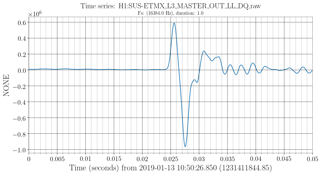
If the overflow caused the glitch, we'd expect the drive value to already be somewhere near 2^19, and for the glitch to happen when it accidentally goes past the overflow value. Instead, the DAC value is generally between +/- 100K. Then during the glitch it has a fast excursion to above 500K in a millisecond.

To look at one of the events, you can grab the times of overflows from the summary pages, e.g. this link. FEC 88 3_4 is one of the ETMX ESD quadrants. The attached plot is a zoom in of the drive signal. At least in this case, it's much more likely that there's a short loud glitch that causes the feedback to overflow, rather than the other way around. This was also the case with overflows that we investigated with the 18-bit DAC on the ESD.

One cause of glitches that worries me is something above the Nyquist sampling rate of this channel, like PI damping. I don't know how RMS that has, or what it would look like if that caused an overflow.
Images attached to this comment
john.zweizig@LIGO.ORG - 17:51, Thursday 31 January 2019 (46732)DetChar

Note that when the DAC was changed from 18-bits to 20-bits a x4 gain stage was added to a filter bank (see alog) apparently to avoid changing all the other constants. I haven't traced out the model, but this would suggest that the saturation would be at 2^17 as before rather than 2^19. There is still a discrepancy between the apparent glitching at ~1.0 rather than ~1.3 but it is much more consistent with a saturation and may be related to the reduction in maximum range discussed elsewhere.

H1 PSL (ISC)
jenne.driggers@LIGO.ORG - posted 14:28, Thursday 24 January 2019 - last comment - 06:44, Thursday 31 January 2019(46626)
FSS noisy sometimes??

Sometimes it seems like the FSS gets noisy, and I don't think anything else is happening in the IFO.

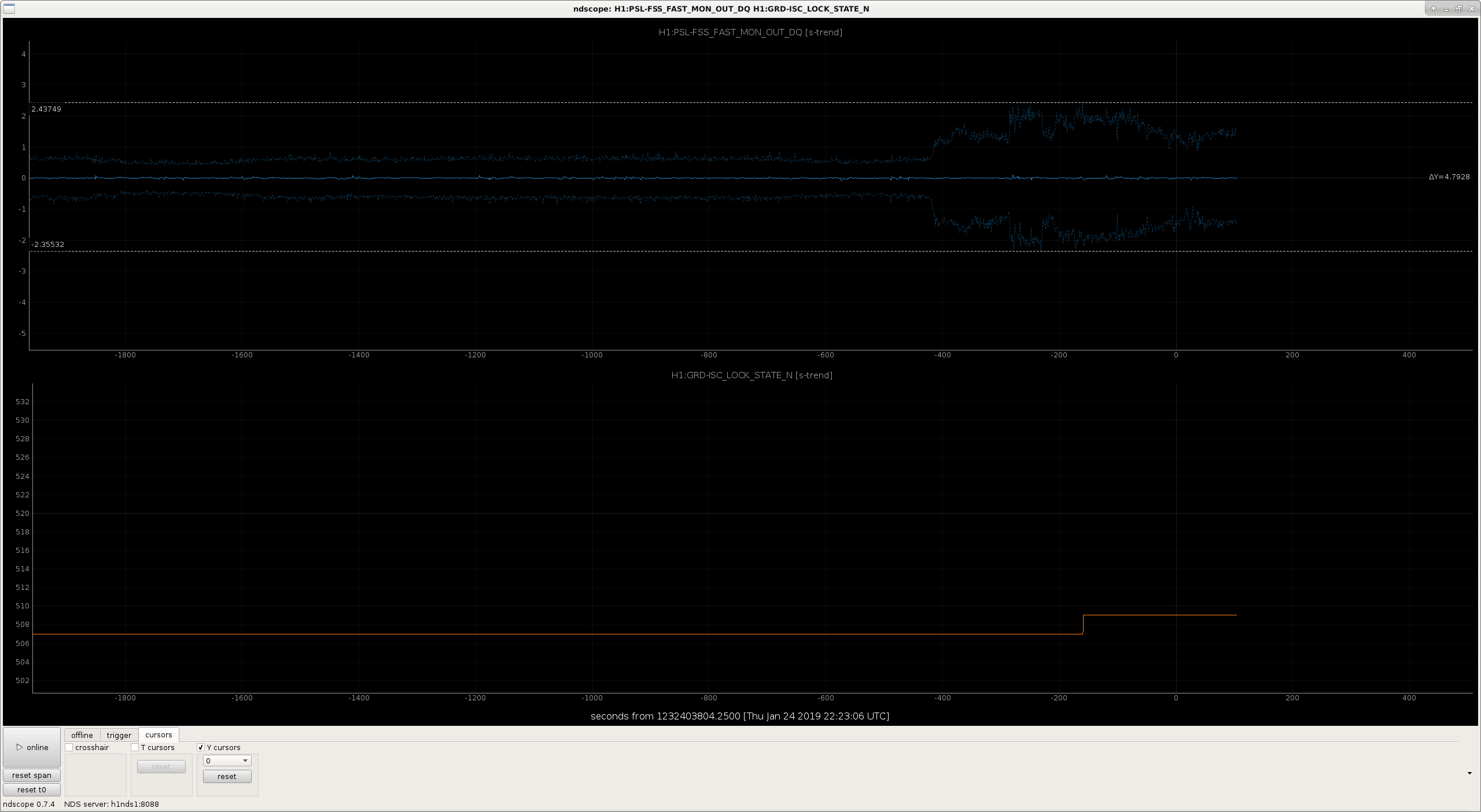
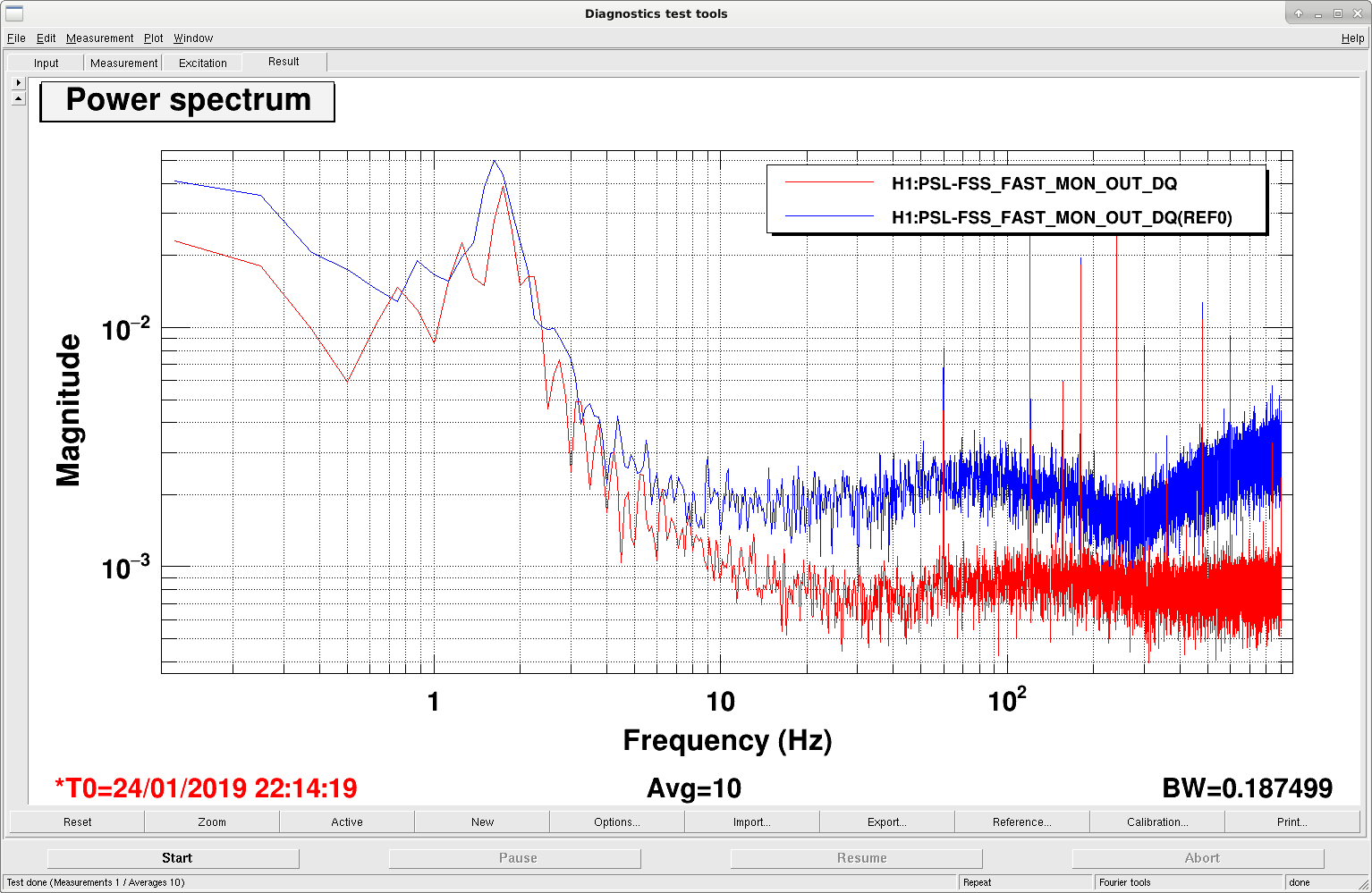
I caught it happening again, and am posting a quick time series and spectrum to show that it's definitely changing.  Does anyone in PSL-land know what this might be?  Perhaps (as Sheila suggests) someone could take a look at PSL PEM sensors to see if anything changed in there?

Images attached to this report
Comments related to this report
jason.oberling@LIGO.ORG - 12:24, Friday 25 January 2019 (46639)DetChar

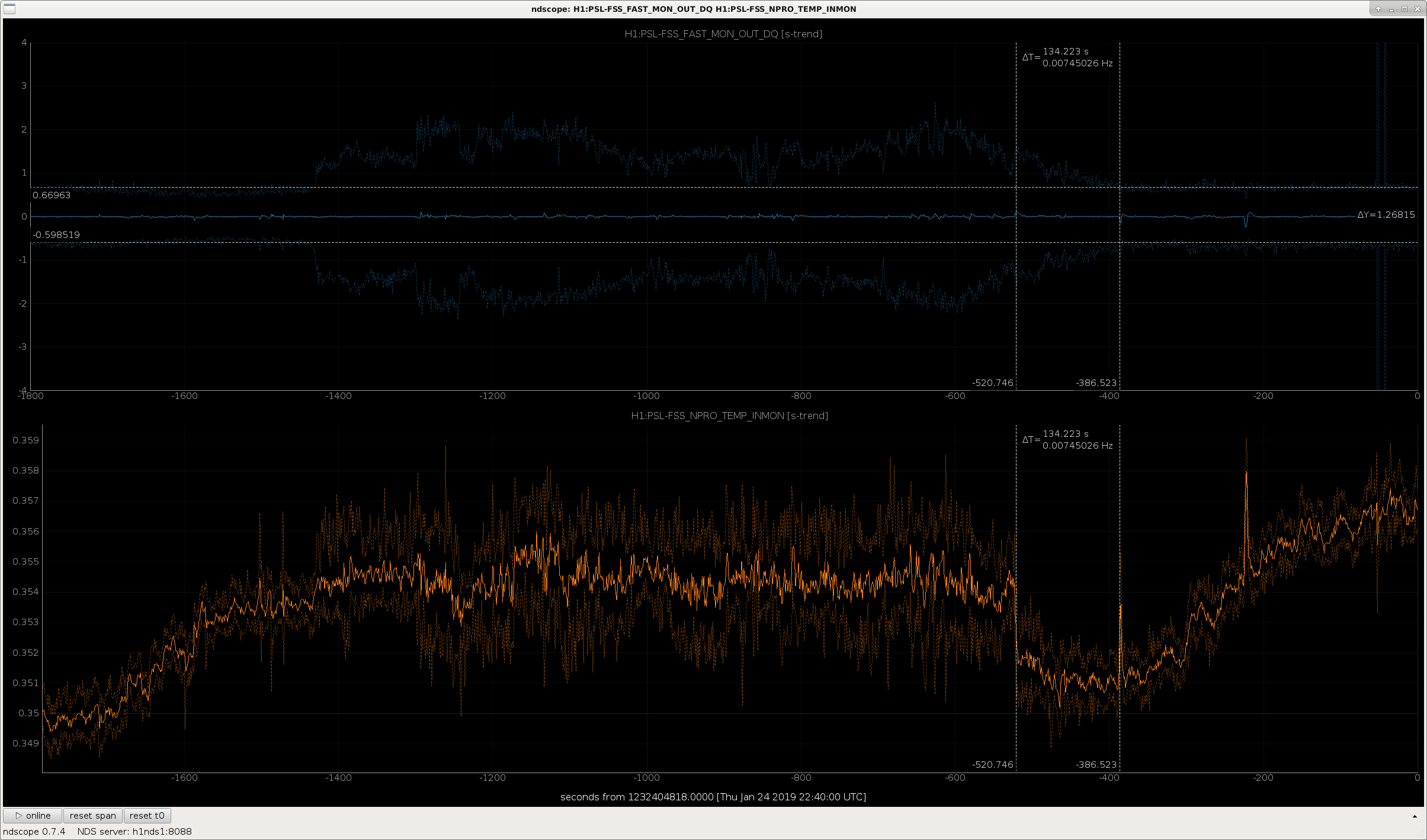
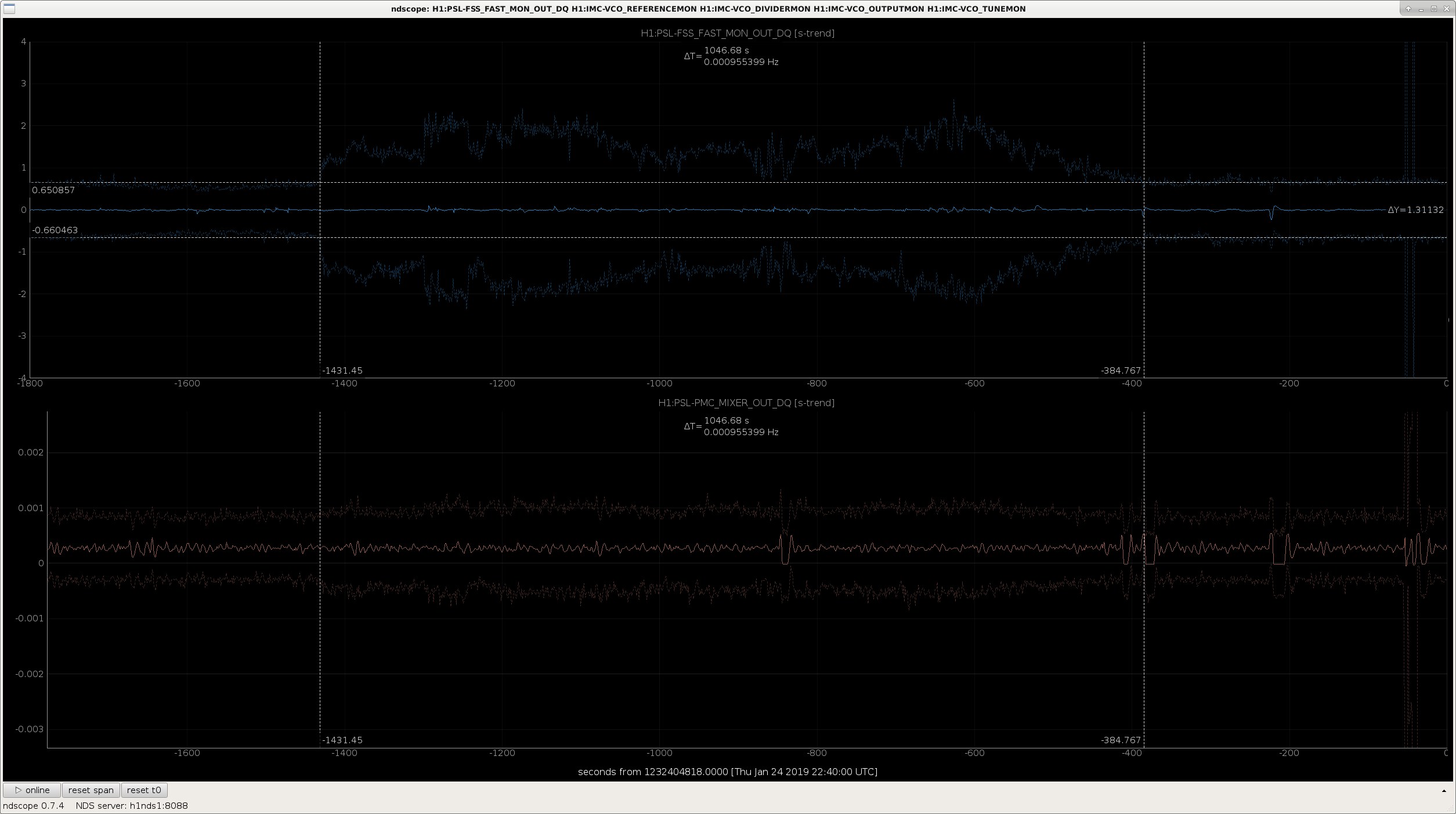
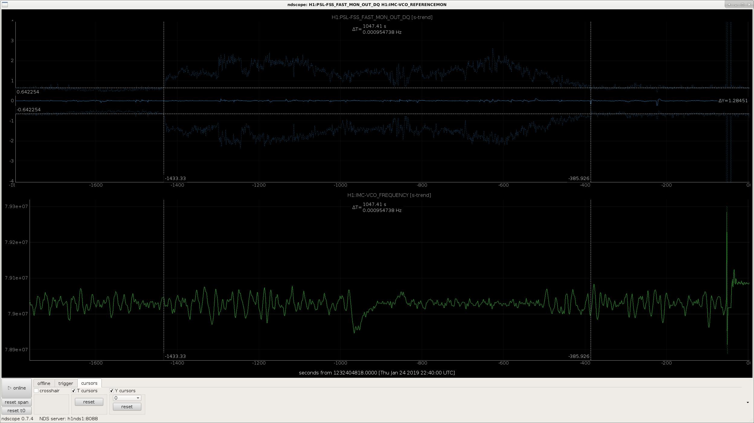
First attachment contains the 2 FSS control channels, the NPRO PZT (fast) and the NPRO crystal temperature (slow), and covers the entire period of the noise "event" Jenne notes above.  As can be seen the noise is visible in both channels (not entirely surprising) and lasts for ~1047 seconds.  ~134 seconds before the NPRO PZT returns to its usual peak-to-peak swings, the NPRO crystal temperature sees a small downward jump and then slowly returns to its normal peak-to-peak behavior over those 134 seconds.

I also looked at several other signals over the same time frame and compared them to the FSS fast signal:

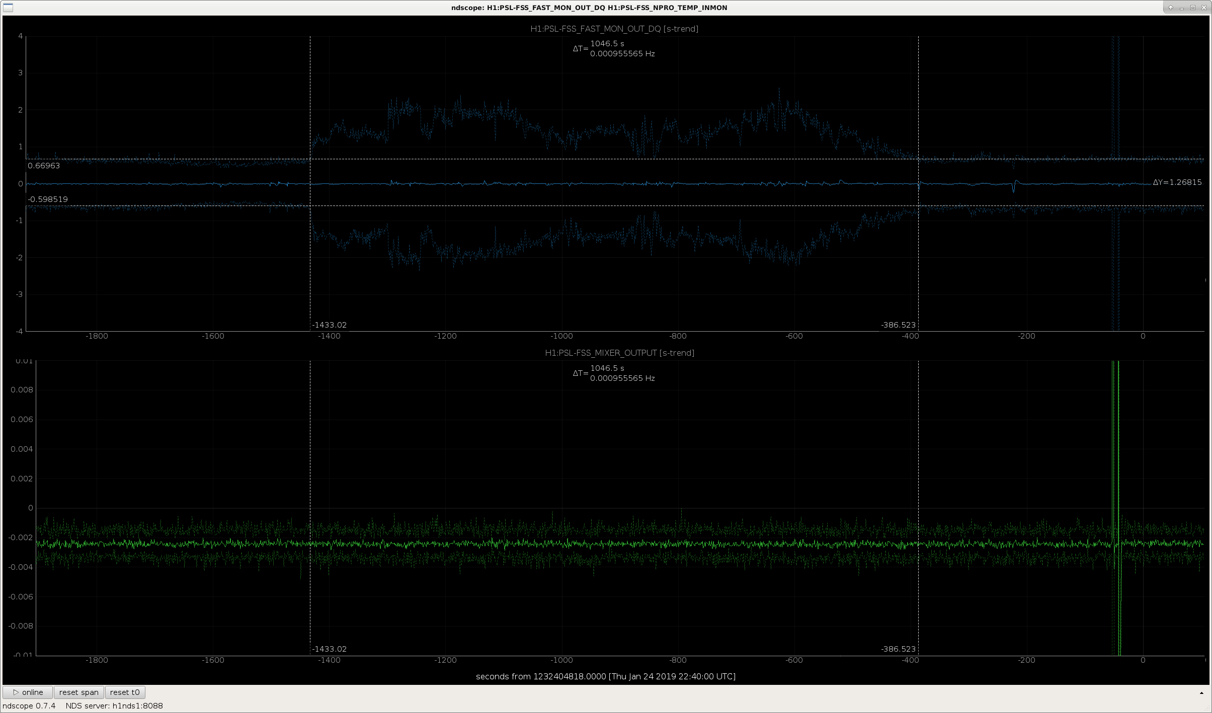
  • 2nd attachment: FSS fast with FSS RefCav mixer
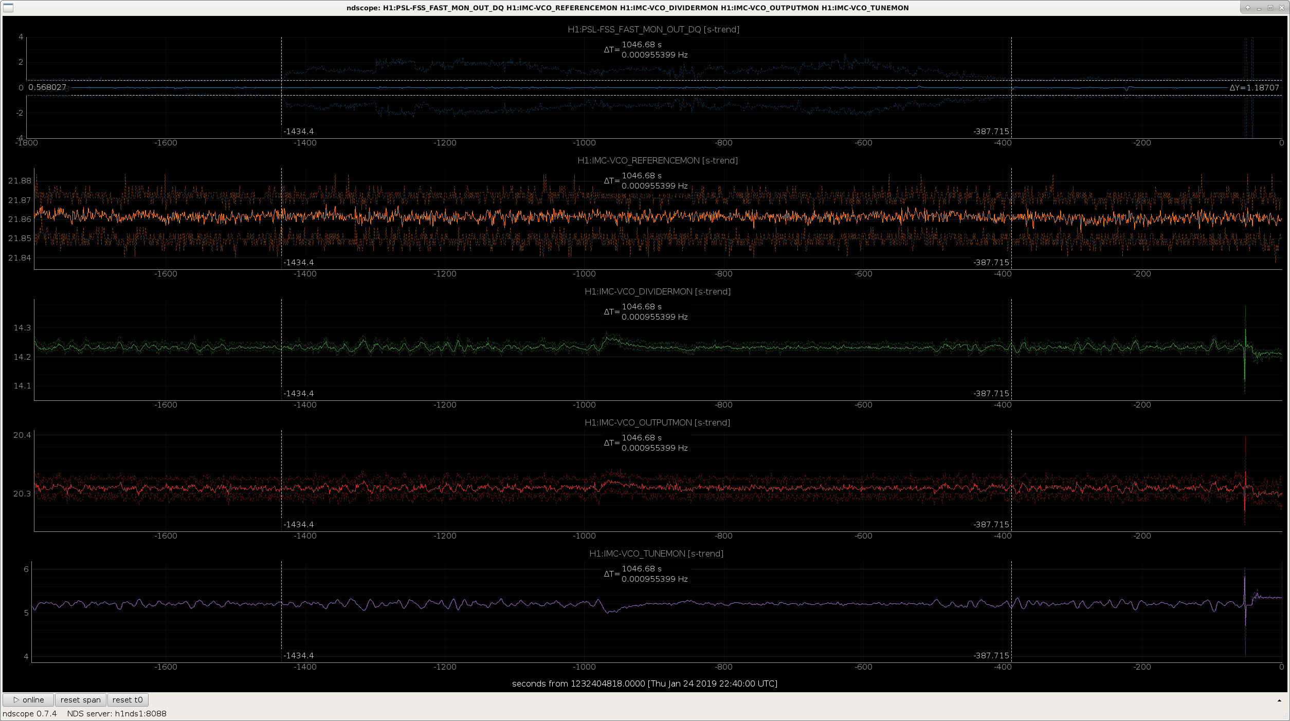
  • 3rd attachment: FSS fast with various VCO signals
  • 4th attachment: FSS fast with PMC mixer
  • 5th attachment: FSS fast with VCO frequency

This noise does not appear in any of these other channels that I can see; so far I've only seen it in the FSS fast and slow channels.  After a quick chat with Peter we have 2 possibilities to explore:

  • Does the noise coincide with VCO whistles?
    • Maybe unlikely, but could someone from DetChar check this?  Thanks.
  • The PSL NPRO could be close to a mode hop region
Images attached to this comment
daniel.sigg@LIGO.ORG - 15:06, Friday 25 January 2019 (46645)

Excess high frequency signals are clearly visible in the PC_MON. This is an RMS measure of the signal sent to the Pockels cell.

Non-image files attached to this comment
kara.merfeld@LIGO.ORG - 11:54, Tuesday 29 January 2019 (46688)DetChar, PEM
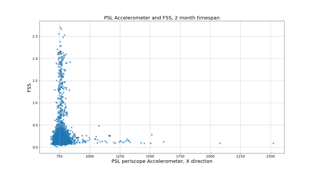
I looked at correlations between the FSS and several PEM monitors in the PSL, these were: the microphone, the dust monitor, and the x-direction accelerometer on the periscope.  I compared the 10s maxima of the PEM channels with the 10s maxima of the FSS over a 2 month span of time using only time segments when the interferometer was in nominal low-noise, and found no correlations.  Attached is a plot comparing the PSL periscope accelerometer, and the FSS.  

Jenne saw this noise in FSS while the interferometer was still acquiring lock, and as long as it doesn't interfere with locking, it shouldn't be a problem.
Images attached to this comment
peter.king@LIGO.ORG - 06:44, Thursday 31 January 2019 (46717)
During the Commissioning Meeting yesterday I kept an eye on the PZT voltage, the laser crystal temperature and the EOM monitor
drive voltage.  The larger fluctuations in the PZT voltage seem to coincide with large values of the EOM voltage.  A brief
discussion with Daniel the other day where he suggested looking at increasing the EOM gain to reduce the EOM voltage since its
average value is somewhat above 0, led me to think about the cross over.

    This morning I moved the cross over around by adjusting the fast gain.  Sure enough increasing the fast gain reduces the
EOM drive and lowering it, increases the EOM drive.  The EOM drive voltage seems to be minimised when the fast gain is set
to 19 dB.  More than this and the EOM drive voltage increases, whilst the PZT remains pretty much the same.  Adjusting the
common gain had little or no effect.

    The cross over bears some re-examination.  The last time this was measured, as I recall, was around the time of the
installation of the 70 W amplifier where a series of transfer function measurements were made.
Displaying reports 43321-43340 of 88618.Go to page Start 2163 2164 2165 2166 2167 2168 2169 2170 2171 End