| Work Permit |
Date |
Description |
alog/status |
| 6659 |
5/25/2017 14:01 |
Move Pcal periscope pre-alignment cradles (white powder-coated steel frames) from near the NE corner of the H2 Laser Area Enclosure to the outside of the vertex, likely in the Large Item Access Area and eventually to the Staging Building. To be done during Tuesday maintenance next week. |
|
| 6658 |
5/24/2017 12:59 |
I will turn h1dns1 server off to survey memory specifications to upgrade it from 48GB to 72GB as recommended on FRS 8198 |
|
| 6657 |
5/24/2017 7:46 |
Test air flows on both end station Axivane supply fans. Calibrate if necessary. |
|
| 6656 |
5/23/2017 15:50 |
Check HEPI Accumulators' charge: Deisolate platforms and spin down HEPI pumps, check and charge Accums AR. Return to full operation. |
duplicate of WP #6655 |
| 6655 |
5/23/2017 15:34 |
Check HEPI Accumulators' charge: Deisolate platforms and spin down HEPI pumps, check and charge Accums AR. Return to full operation. |
36356, 36373 |
| 6654 |
5/23/2017 13:19 |
Replace leaking ball valve assembly on Crystal Chiller return line. Will require shutting down the PSL while the valve is being replaced. |
36343, 36393 |
| 6653 |
5/23/2017 12:59 |
Connect and run a pump cart at HAM11 annulus pump port (South side of HAM11). Replace whatever is broken. May require admitting gas into the annulus volume if the pump body requires replacement. |
|
| 6652 |
5/23/2017 9:07 |
Connect BRS vacuum pressure readback signals to Vacuum System at end stations. Vacuum controls chassis S1600286 and S1600287 will need to be modified. Wiring diagram E1500368 and E1500369 will need to be updated. Software model will need to be updated to add new channels. |
36396 |
| 6651 |
5/23/2017 8:49 |
Perform regular PCal calibration measurements at both end stations. The will require the end station to be laser hazard while the work is being performed. |
36431 |
| 6650 |
5/22/2017 18:00 |
Test 118MHz modulation & replace IMC RFPD. |
36354 |
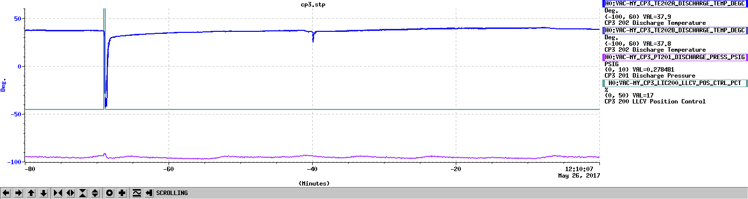
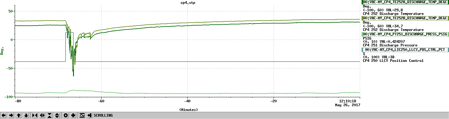
| 6649 |
5/22/2017 12:42 |
Increase upper limit of thermocouple temperature validity check in scripts to autofill CP3 and CP4. |
|
| 6648 |
5/22/2017 11:35 |
Measure the transfer function of the RFPD (24 MHz for locking the IMC) in situ with the AM laser at IOT2L in order to determine whether the installed unit has the correct resonance at 24 MHz or not. During the measurement the IMC will not be able to lock. |
|
| 6647 |
5/22/2017 11:13 |
Remove EX and EY Instrument air cell phone alarms. |
|
| 6646 |
5/22/2017 10:58 |
Replace 24V power to one of the Inficon gauges on BSC6. Power to both Inficon gauges will now come from the Vacuum rack. A new interlock signal cable will need to be pulled from BSC6 chamber to the ESD Safety Relay interlock box. ESD HV power supplies will need to be powered off for part of this work. |
|
| 6645 |
5/22/2017 6:20 |
Erect scaffolding in the SW corner of the CER room to access a very strategically placed VAV box for the HVAC controls upgrade. |
|
| 6644 |
5/20/2017 18:50 |
This Work Permit replaces WP #6643 Monday, 5/22 -> Turn off High Voltage sources in Vertex vacuum volume. Dump unpumped Vertex RGA volume into combined Vertex+YBM+XBM turbo-pumped volumes. Energize Vertex RGA filament. Energize IP1. Valve-in IP2-IP6. Valve-out Vertex, YBM and XBM turbo pumps. Tuesday, 5/23 -> Take RGA scan of combined Vertex, YBM and XBM vacuum volumes. Shut down Vertex, YBM and XBM turbos. Dump GV5 and GV7 unpumped gate annulus volumes into annulus ion pumped volume or attached pump cart if required. Disconnect pump cart(s) if applicable. Open GV5 and GV7. |
36362, 36380 |
| 6643 |
5/19/2017 19:01 |
Monday morning, May 22nd -> While still pumped by Vertex, YBM and XBM Turbos, slowly "crack" open the 2 1/2" metal isolation valve that separates the Vertex RGA from the Vertex while closely monitoring the Vertex pressure (dump RGA volume into pump cart prior to opening 2 1/2" isolation valve to a significant degree if deemed necessary) * Energize Vertex RGA filament |
|
| 6642 |
5/19/2017 14:43 |
NOVA Film Crew will set up on the roof of the OSB, a minimum of 6 feet from any edge to shoot down the arms. Escorted by Vern and myself. |
|