J. Kissel
Over the past few days, I've been filling in the infrastructure I'd installed on Tuesday to use the 7.93 Hz PCAL line to calculate the SRC Detuning Spring frequency, f_s, and Quality Factor, Q_s, as a function of time.
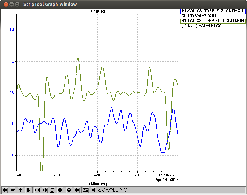
The message: the output is functional, the spring frequency is reported as ~7.5 +/- 1.5 and the Q is ~0 +/- 20 (by eye, via StripTool; see 1st attachment). This agrees with results previously shown with reference measurement sweeps (e.g. LHO aLOG 35361), and with prototype results from the gst-lal pipeline (e.g. LHO aLOG 35041).
The new sping frequency and Q can be tracked with the following EPICs (16 Hz) channels:
H1:CAL-CS_TDEP_F_S_OUTPUT
H1:CAL-CS_TDEP_Q_S_OUTPUT
Details:
----------
(1) Filling out the infrastructure
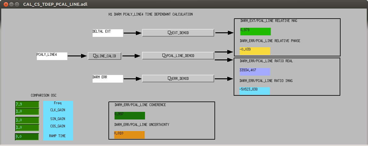
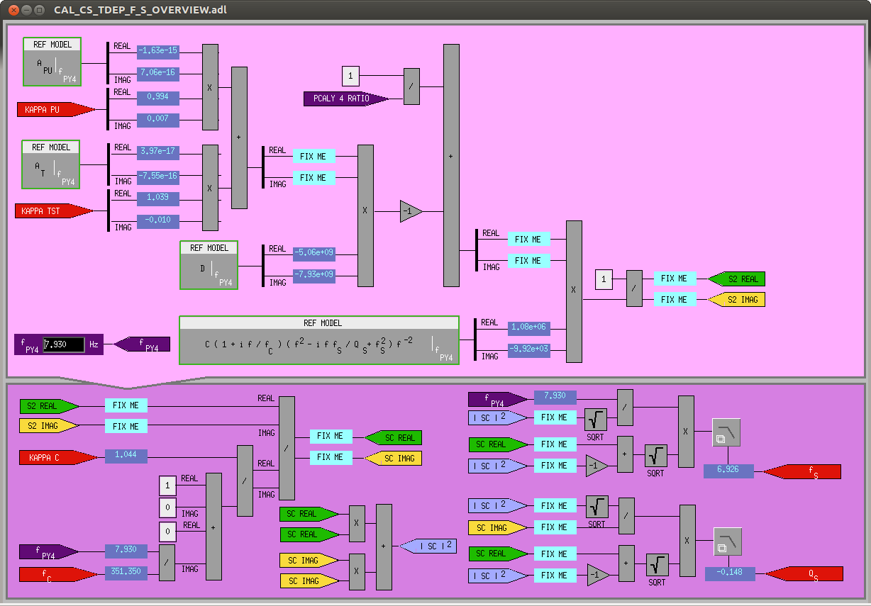
The signal flow for the SRC detuning goes as follows:
DARM_ERR (uncalibrated) and PCALY_RX_PD (calibrated into "m", save for a missing two, 1 Hz poles and "high-frequency" corrections) are fed into two demodulators, respectively (with the PCAL signal filtered to multiply in the missing 1 Hz poles). The complex ratio of these demodulator output is then passed into a calculation block that follows math from section 2.4 of T1700106, absorbing reference DARM loop model parameters calculated at 7.93 Hz (stored as EPICs records), and other pre-calculated time-dependent correction factors, kappa_TST, kappa_PU, kappa_C, and f_c.
For most of the infrastructure, I mostly copied pre-existing filters,
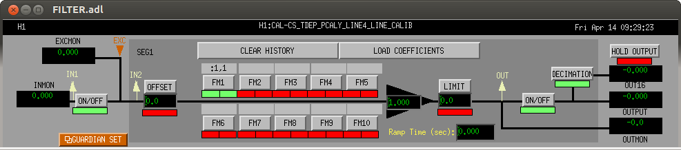
- a two, 1 Hz poles filter to finalize the calibration of the PCALY RXPD signal into [m] of DARM in the H1:CAL-CS_TDEP_PCALY_LINE4_LINE_CALIB bank, designed as
":1,1" zpk([],[1;1],-1,"n")
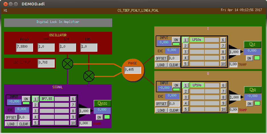
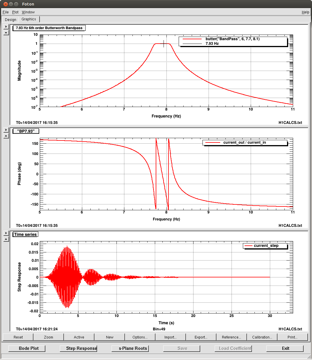
- all demodulators get a 7.93 Hz, 6th order band pass in their H1:CAL-CS_TDEP_PCALY_LINE4_[EXT,PCAL,ERR]_DEMOD_SIG banks, designed as
"BP7.93" butter("BandPass",6,7.7,8.1)
(different from the other band-passes only in frequency and pass-band, for obvious reasons)
- all demodulators get a 1 [ct] CLK, SIN and COS GAIN just so these digital demodulators spit out a synchronized clock signal against which the generating oscillators are compared
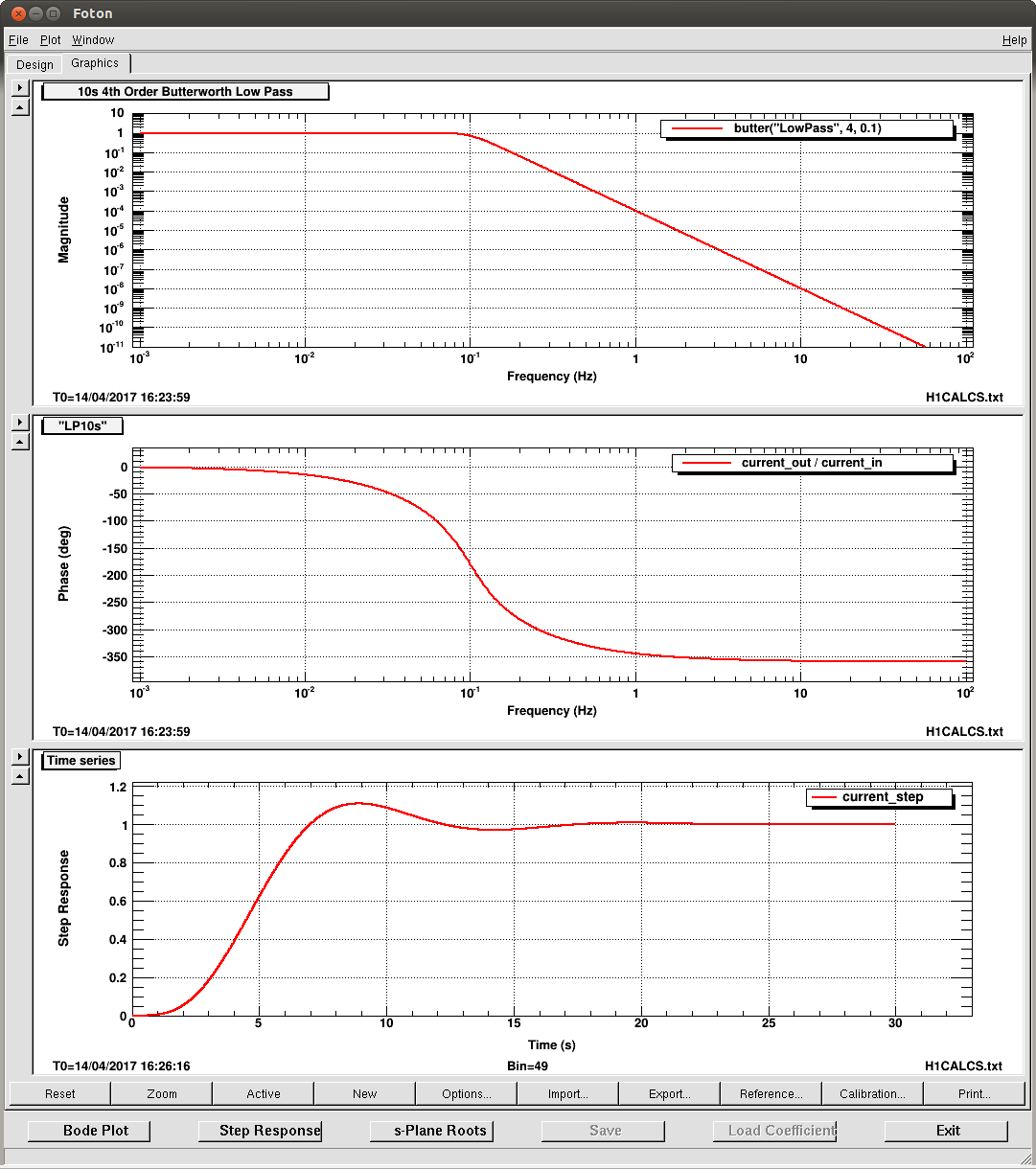
- all demodulators get a 10 sec low-pass on their I and Q demodulated signals in the H1:CAL-CS_TDEP_PCALY_LINE4_[EXT,PCAL,ERR]_DEMOD_[I,Q] banks, designed as
"LP10s" butter("LowPass",4,0.1)
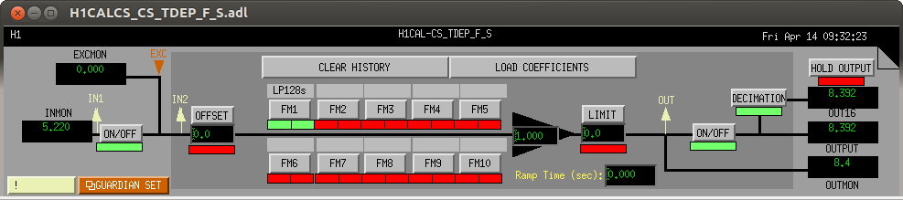
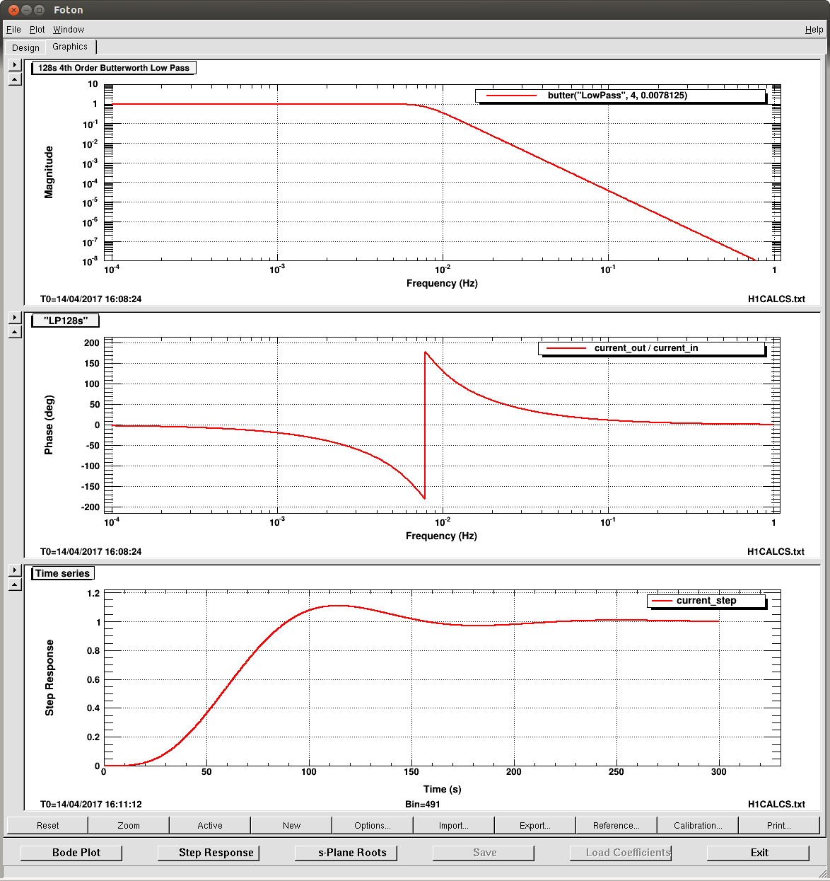
- the final output of the spring frequency and Q calculations get a 128 sec 4th order butterworth low-pass in the H1:CAL-CS_TDEP_[F_S,Q_S] bans, designed as
"LP128s" butter("LowPass",4,0.0078125)
For the demodulation phase of the H1:CAL-CS_TDEP_PCALY_LINE4_PCAL_DEMOD_PHASE, I resurrected the script used for the other line frequencies,
/ligo/svncommon/CalSVN/aligocalibration/trunk/Runs/ER10/H1/Scripts/PCAL/getPcalCorrForCALCSdemod.m
updating it to use the modern DARM model infrastructure and to calculate a value for the 7.93 Hz line. It has subsequently been committed. Recall that this phase is the remaining "high-frequency" corrections to the PCAL RXPD signal that are the result of AA filters and delays in the signal path that are, by convention alone, not included in the ":1,1" calibration filter mentioned above.
Finally, I reproduced the calibration line frequency in the EPICs record H1:CAL-CS_TDEP_D2N_SPRING_PCAL_FREQ which is yet another copy of that's buried in the TDEP_D2N_SPRING corner of the h1calcs.mdl simulink model. If I were to make this model again, I would pipe the first copy of these records in the H1:CAL-CS_TDEP_${LINE_NAME}_COMPARISON_OSC_FREQ out and up and through the model over to where ever else they're needed.
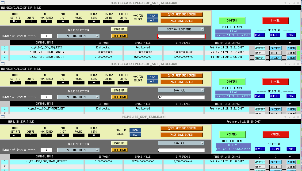
All EPICs changes (including turning on all new filters) have been accepted into the SDF system.
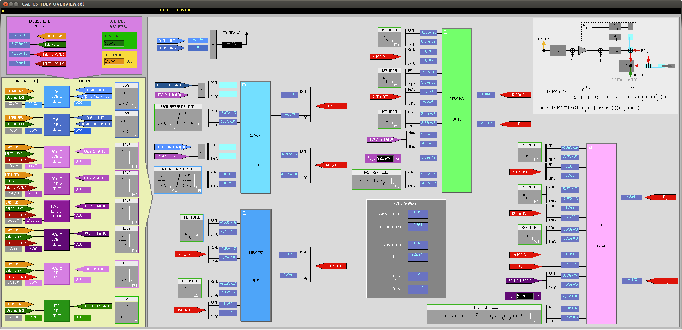
(2) Re-drawing the MEDM infrastructre
The TDEP overview has been begging for an upgrade for quite some time. With the new version, I've
- (hopefully) created a clear signal flow blocking out the order of operations
- added some (hopefully) helpful math and diagrams,
- buried the math and calculations in sub-sub blocks
- showed as many EPICs records as possible to help the user walk through the math and debug
- reduced the precision on the EPICs records that are reproductions of the DARM loop model for cleanliness (and 5 sig-figs aren't really needed for this kind of display)
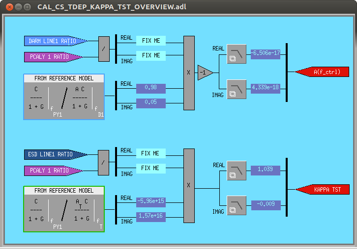
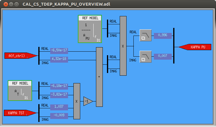
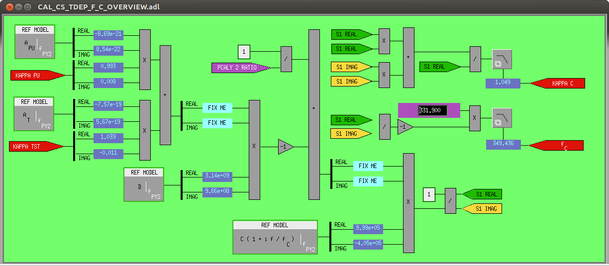
- displayed the "final answer" with all the calculated time dependent correction factors in one obvious block in the middle
The following screens (some brand new) have been committed to the svn repo:
/opt/rtcds/userapps/release/cal/common/medm
CAL_CS_TDEP_OVERVIEW.adl
CAL_CS_TDEP_F_C_OVERVIEW.adl
CAL_CS_TDEP_F_S_OVERVIEW.adl
CAL_CS_TDEP_KAPPA_PU_OVERVIEW.adl
CAL_CS_TDEP_KAPPA_TST_OVERVIEW.adl
CAL_CS_TDEP_OVERVIEW.adl
(3) Still to do:
- You may notice that there are several "FIX ME"s where EPICs records should be on the MEDM screens. These EPICs records don't exist yet because I hadn't drawn a clearly flowing MEDM screen and/or hadn't decided which EPICs records would be necessary. Now that I have a good idea of what helps the reader (and the expert debug potential problems) I'll add these records to the simulink model and reboot next Tuesday (Apr 18).
- Everyone is still suspicious of the calculation of the Q. Of course a negative Q is unphysical, and when the calculation produces such a result, it's likely due to noise. We need to further investigate / improve the algorithm such that we get only physical results if we ever want to use this to do live corrections to the h(t) data stream. Stay tuned on that.