TITLE: 12/13 Owl Shift: 08:00-16:00 UTC (00:00-08:00 PST), all times posted in UTC
STATE of H1: Observing at 72.9978Mpc
OUTGOING OPERATOR: Patrick
CURRENT ENVIRONMENT:
Wind: 10mph Gusts, 8mph 5min avg
Primary useism: 0.02 μm/s
Secondary useism: 0.15 μm/s
QUICK SUMMARY:
8:11-9:30UTC (12:11-01:30amPST): No Operator Coverage (Due to Winter Weather this week, I'll be taking the OWL shift for next 3 nights.)
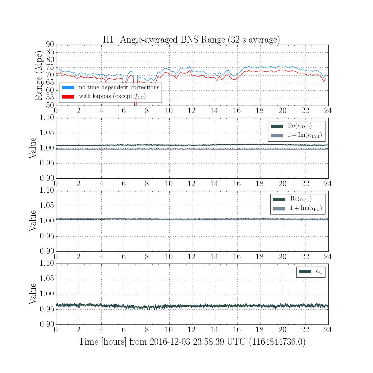
Arrived to an H1 in OBSERVING & a quick scan looks like we have optimal conditions (range is at 70Mpc). Glancing at range over last 12hrs, range has 8hr period of going up to 75Mpc & down to 70Mpc(now) & I don't see anything seismically which matches that (useism has had a constant trend down over the last 24+hrs). There are also a few more glitches (i.e. drops in range) for this lock.
Low Useism: Seismically, we appear to be a tad under the 50percentile for useim (a comparison personal note between 90+percentile over the weekend & now is that the Tidal striptool is virtually flat vs over the weekend you would definitely see useism waves/oscillations at 90+%).
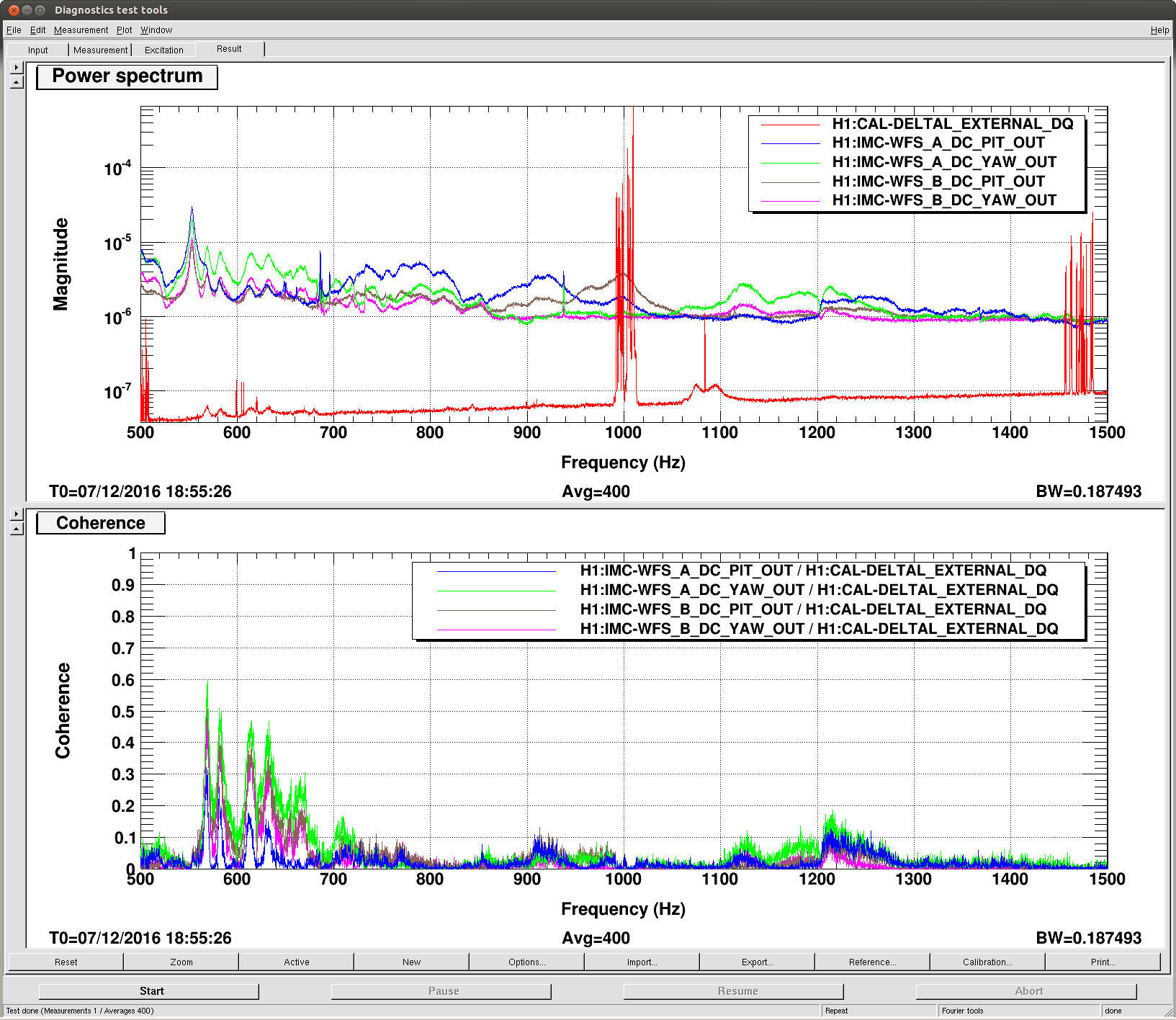
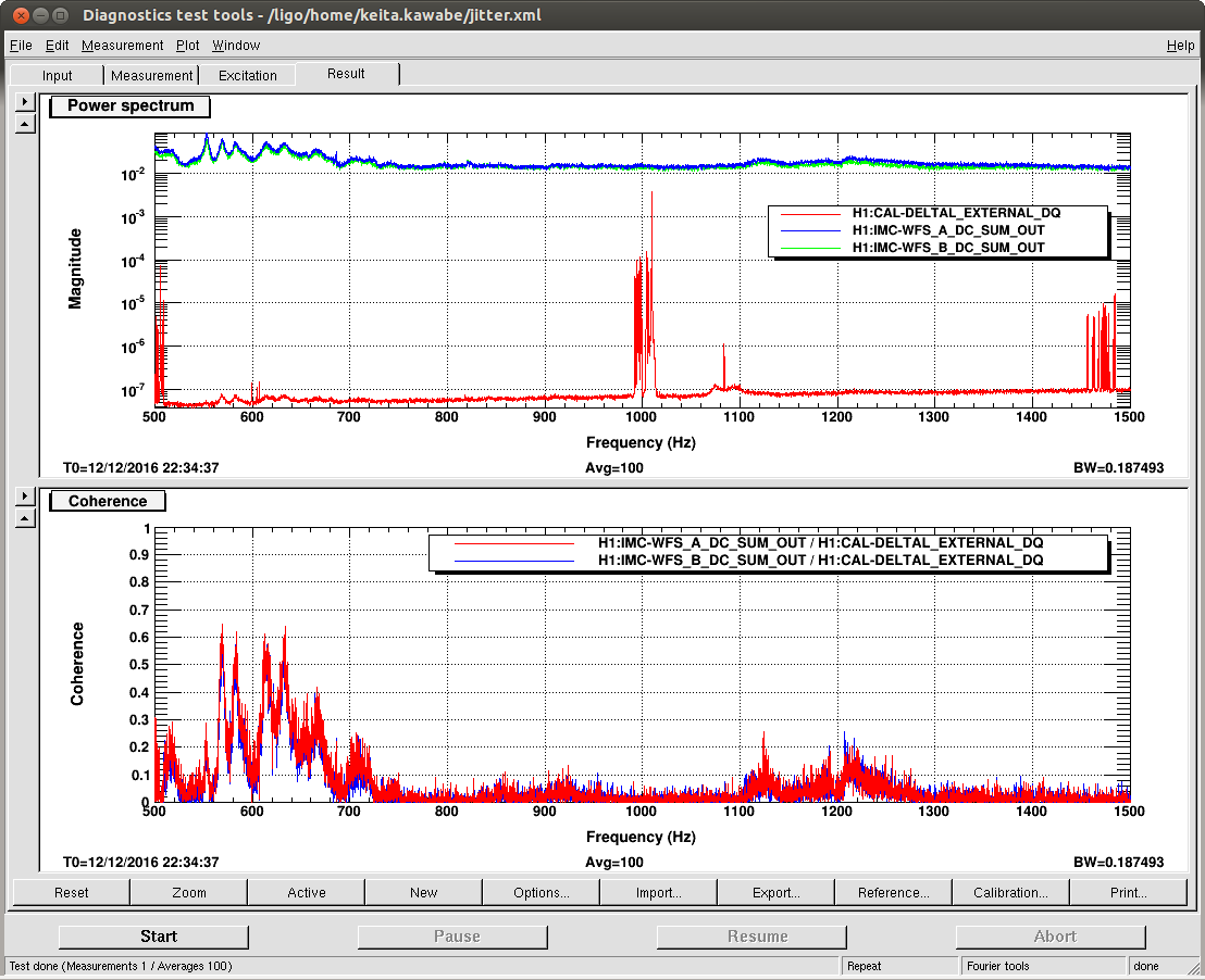
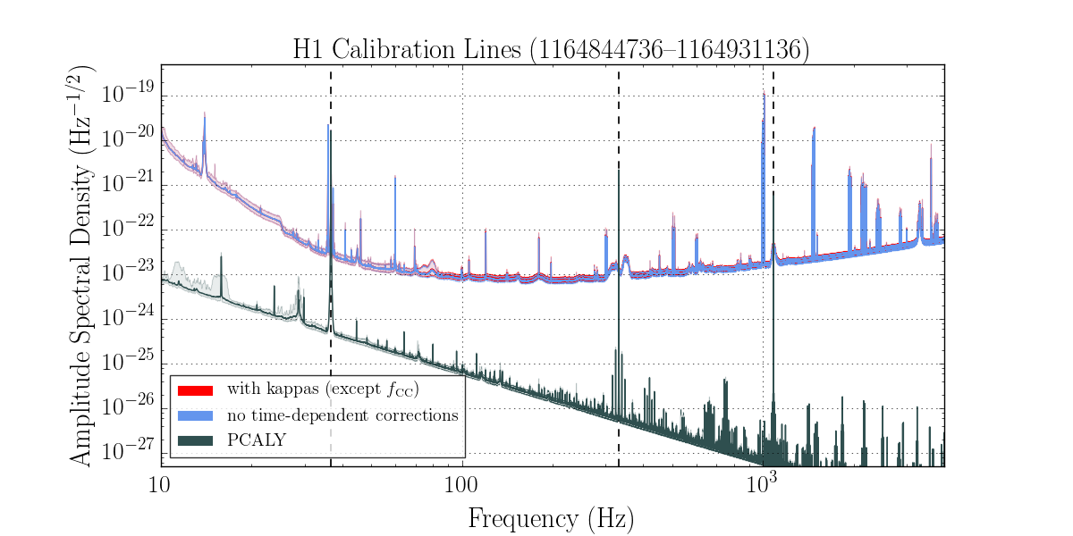
Violin Modes: Fundamental(~500Hz) looks to be just above 1e-19 on DARM. Second Harmonic (~1kHz) is just above 1e-15, this is the only notable feature on the "H1Glitches(DMT Omega)" tool on nuc0 (perhaps this is something which could be damped at an opportune time [Maintenance Day?]).
Talked with Fyffe @LLO to inform they are no longer flying solo.
Weather Conditions: No precipitation & cloudy.
Road Conditions: (driving in via Twin Bridges) Other than my driveway at home & driveway on-site, the roads were dry and clear (able to easily drive speed limit); made it to site in the standard 20-25min. I did come across a heard of deer right near the bridges.
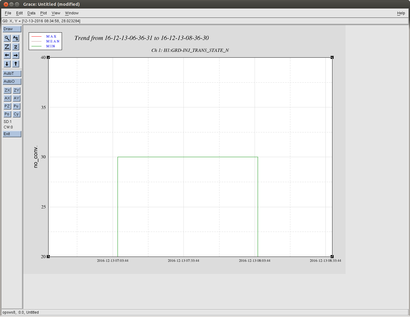


Nutsinee has requested that someone reload the DIAG_MAIN guardian if
the IFO loses lockwe go out of observing. (see whiteboard)