|
Work Permit |
Date |
Description |
alog/status |
|
6310.html |
2016-11-08 11:14 |
Mount scroll pump on previously installed unistrut framing within Turbo pump stand*Test functionality of Turbo "safety valve" interlock when control cable is connected to scroll pump box*Requires running both pumps for a few minutes |
31325 |
|
6309.html |
2016-11-08 08:44 |
Perform scheduled maintenance to scroll compressor #1, #2 @ X-MID vent/purge-air supply skid. Maintenance activity will require for the compressors to run for brief periods of time. Lock-out/tag-out power to skid. |
31339 |
|
6308.html |
2016-11-07 23:19 |
Install gstlal-calibration-1.0.7 on the DMT. * Bug fixes to the demodulation routine for kappa calculations (https://alog.ligo-la.caltech.edu/aLOG/index.php?callRep=29156) * Addition of six new channels for un-gated kappas in h(t) frames * Removal of two deprecated channels in h(t) frames |
31315 |
|
6307.html |
2016-11-07 22:38 |
Turn off automatic turn on on power failure on Beckhoff BRS computers in bothe end stations and install KVM cables in both as well |
31327 |
|
6306.html |
2016-11-07 14:23 |
update H1EDCU_HWS.ini file to latest HWS python code EPICS channels. DAQ restart required. |
31327 |
|
6305.html |
2016-11-07 14:12 |
Request for Fred to give a tour of the LVEA for Bill Althouse (LIGO's 1st Chief Engineer) on Thurs (11/10). |
|
|
6304.html |
2016-11-07 13:57 |
Tour of facilities by a group from the University of Utah. |
|
|
6303.html |
2016-11-07 12:45 |
Rebuild daqd on h1fw2 against a newer FrameCPP (the version installed at LLO) which has an updated leap second table. We will compare the frames generated by h1fw2 with the production machines to verify it is safe to update h1fw0 & h1fw1 next week. |
31310, 31327 |
|
6302.html |
2016-11-07 10:43 |
Re-center active H1 optical levers. This includes ETMx, ETMy, ITMx, ITMy, BS, PR3, and SR3. These optics need to be in their "Aligned" state for the duration of the re-centering. No viewports will be exposed during this work. |
31333 |
|
6301.html |
2016-11-07 10:40 |
Tweak the PSL prior to LHO entering ER10. This will involve tweaking the beam alignment into the FSS Reference Cavity, checking the beam alignment through the FSS AOM, and tweaking the HPO pump diode currents so the HPO is operating at an optimal power level. |
31326 |
|
6300.html |
2016-11-07 10:38 |
Improve PMC mode matching. This will be done by moving mirrors L02 and L03, and possibly L01. Depending on whether or not we need to move L02, we may need to move mirror M37 for clearance purposes. M37 directs the 1st order diffracted beam from the ISS AOM into a beam dump, so moving this mirror will require a re-alignment of this beam path. This work will also require re-aligning the beam into the PMC. |
31326 |
|
6299.html |
2016-11-07 09:45 |
Renew SSL certificate for marble |
|
|
6298.html |
2016-11-07 07:48 |
Change lights in mechanical room at Y End per FRS 6417. This FRS was filed on M Y but I talked to the person that filed the report and it is actually E Y. We will need to transport the single man lift to the end station for this work. |
|
|
6297.html |
2016-11-07 07:41 |
Bail tumbleweeds near the H-2 electronics building and possibly along the Y arm, time permitting. |
|
|
6296.html |
2016-11-04 15:24 |
Weekend work. Isolate the water at different buildings individually in an attempt to locate a water leak. This work may be done on Saturday or Sunday or both depending on how many people are on site. |
|
|
6295.html |
2016-11-02 12:21 |
Activity: modify the models h1pemex, h1pemey and h1lsc to record ESD power supply monitor channels to the DAQ. To avoid changing the common LSC.mdl this DAQ-block will be added to h1lsc.mdl. DAQ restart and permission to add 9*4096 chans to frame needed. |
31327 |
|
6294.html |
2016-11-02 12:08 |
Install low pass filtering in the DAQ readbacks of the IMC servo board. |
|
|
|
|
|
|
|
UPDATES of PRIOR POSTINGs |
|
|
|
|
6287.html |
2016-10-31 14:27 |
Add an extra PEM ADC to the h1oaf0. Shuffle the new ADC with the one used by h1ngn. h1iopoaf0 model change. DAQ restart. |
31075, 31316, 31327, 31308 |

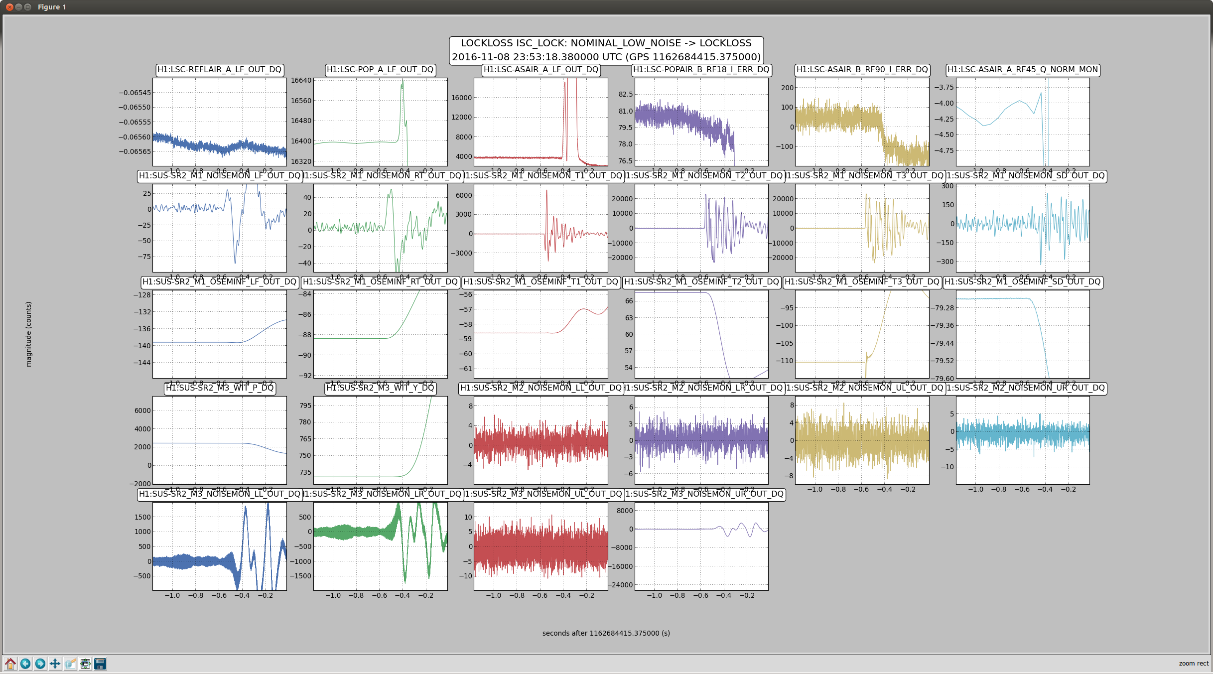

Lockloss tool cannot connect.