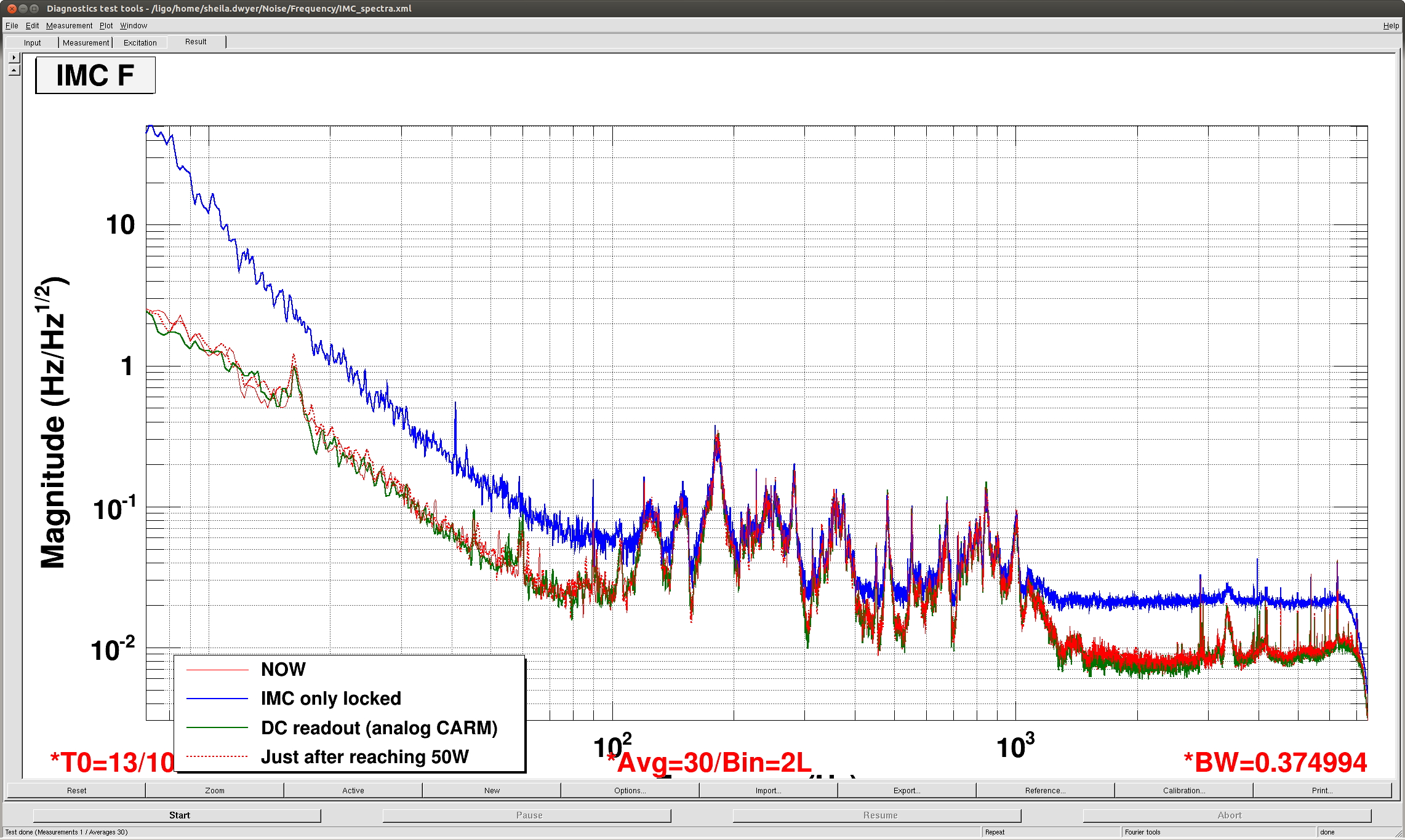
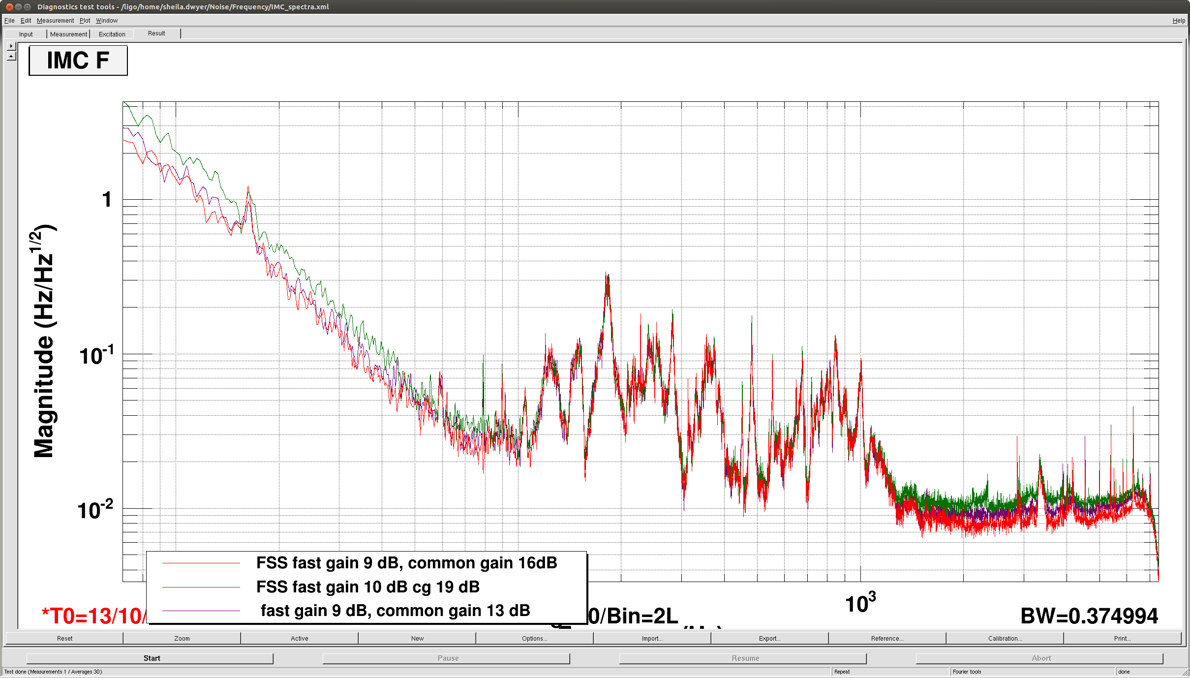
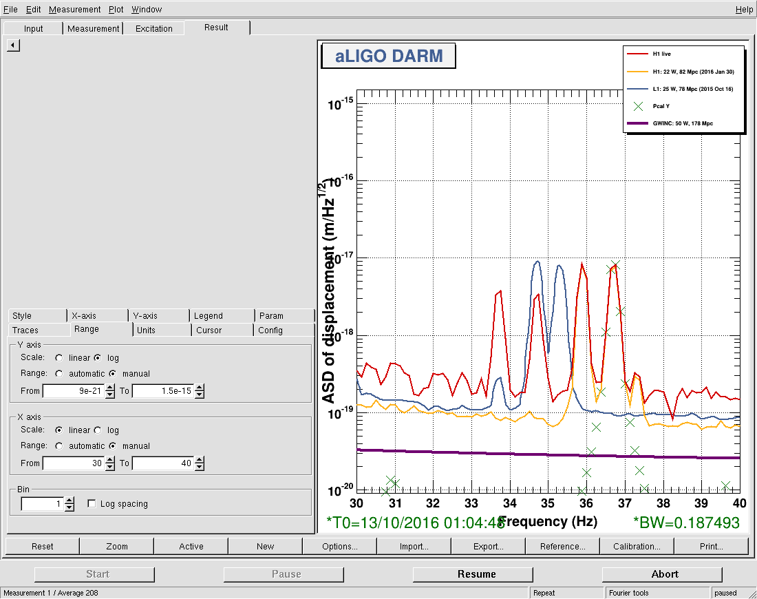
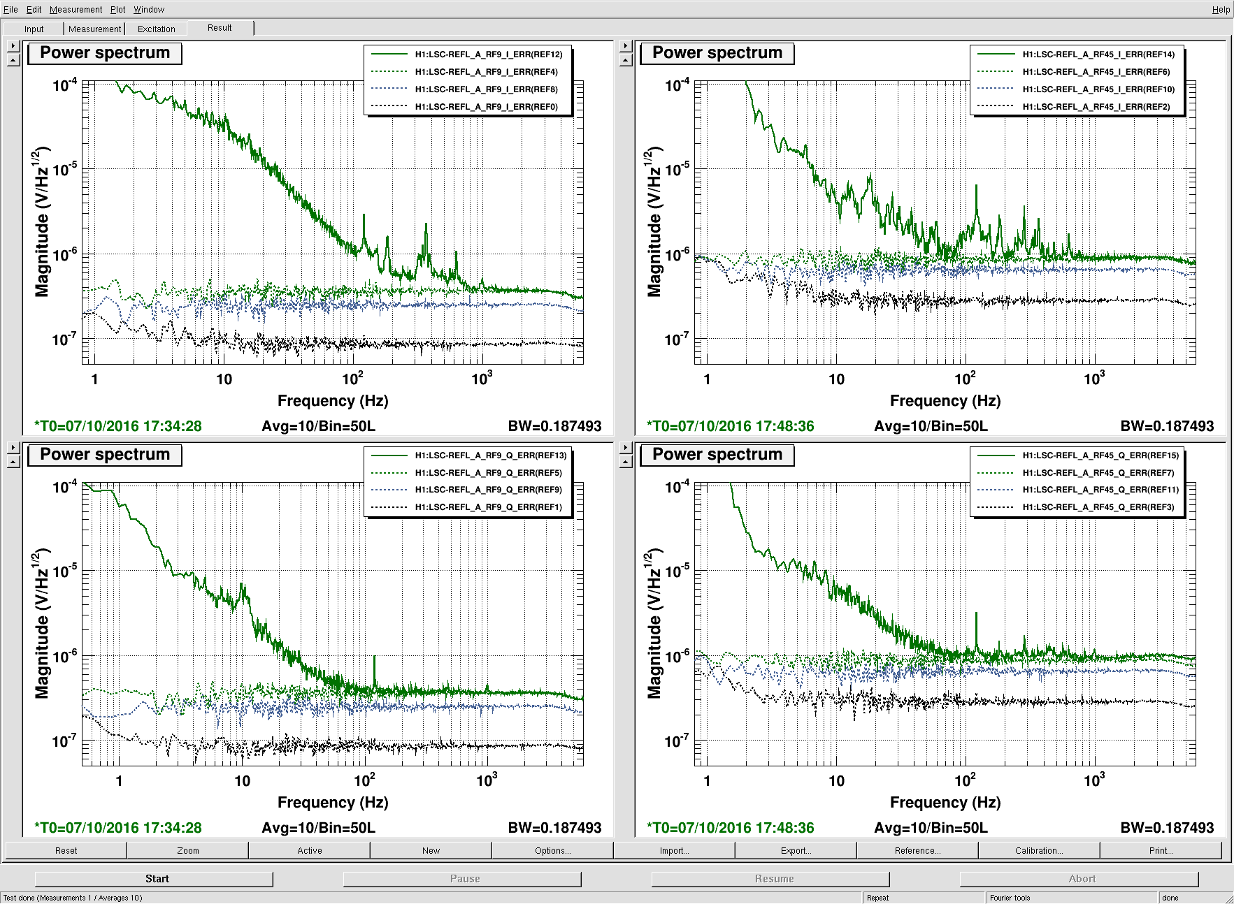
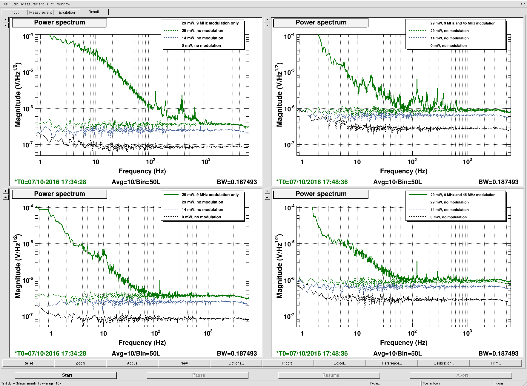
Summary: I have moved the POP_A and SOFT offsets to find better recycling gain (31.2ish rather than the 29.5 we had been getting). I was hoping that this would help eliminate the peaks in the 200-900 Hz region, and I think it did a bit, although not as much as I'd hoped. It did help the high frequency noise "tail" though.
History: Some time ago, Sheila and I moved the POP_A offsets to improve the recycling gain from 25ish, and that worked very well and has been very consistent. At the time, we stopped where we did because the POP_X centering PZT was hitting its rail, not because we thought we had found the best possible location. Then, we elected to move on to trying to get to low noise rather than continuing to chase alignment offsets. Now that we're at low noise though, I wanted to see if continuing to move the QPD offsets would help get rid of some of this jitter / frequency noise coupling.
What I did:
-
Moved POP_A offsets to maximize recycling gain. Watched to ensure POP_X PZT wasn't railing. Moved SRM alignment sliders to keep POP90 low.
-
Upon relock, let the DRMI ASC move the IFO (including SRM) closer to the place that was good for the new POP_A offsets (i.e., just leave the offsets in permanently). This was good, and meant that SRM didn't need to be moved by hand later. I think it does make the CHARD engaging do a little more work, although that can be ameliorated by resetting all of our initial alignment setpoints.
-
Upon relock, also noticed that when the SOFT loops came on, we went through a max for the power recycling gain then came down a bit, all before powering up. This indicated that I needed to move some SOFT offsets.
-
Moved the SOFT offsets, while moving SRM to keep POP90 low.
-
Went back to re-try POP_A offsets, ended up adjusting pitch a little more.
-
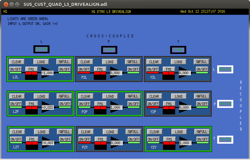
Ran A2L for the test masses.
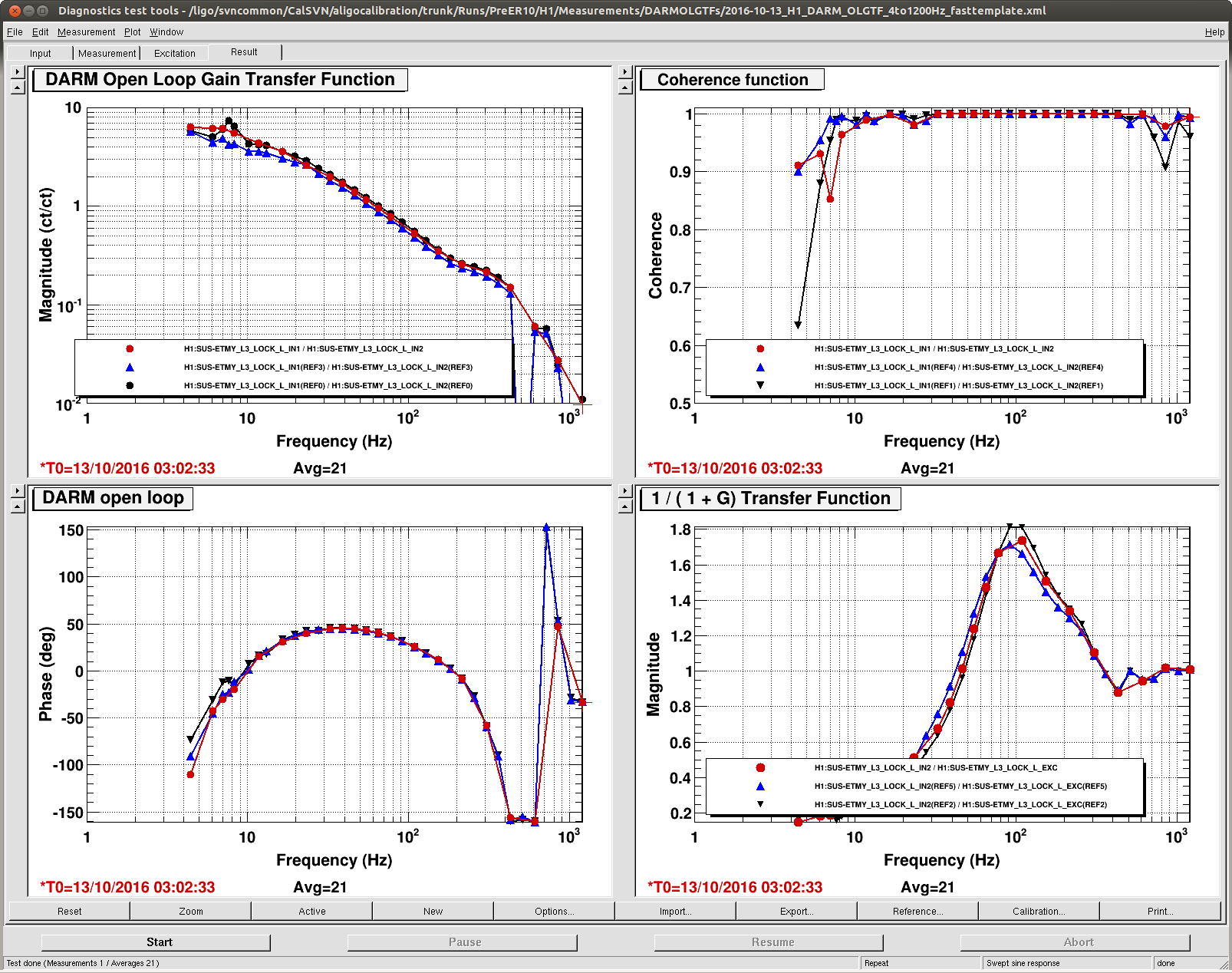
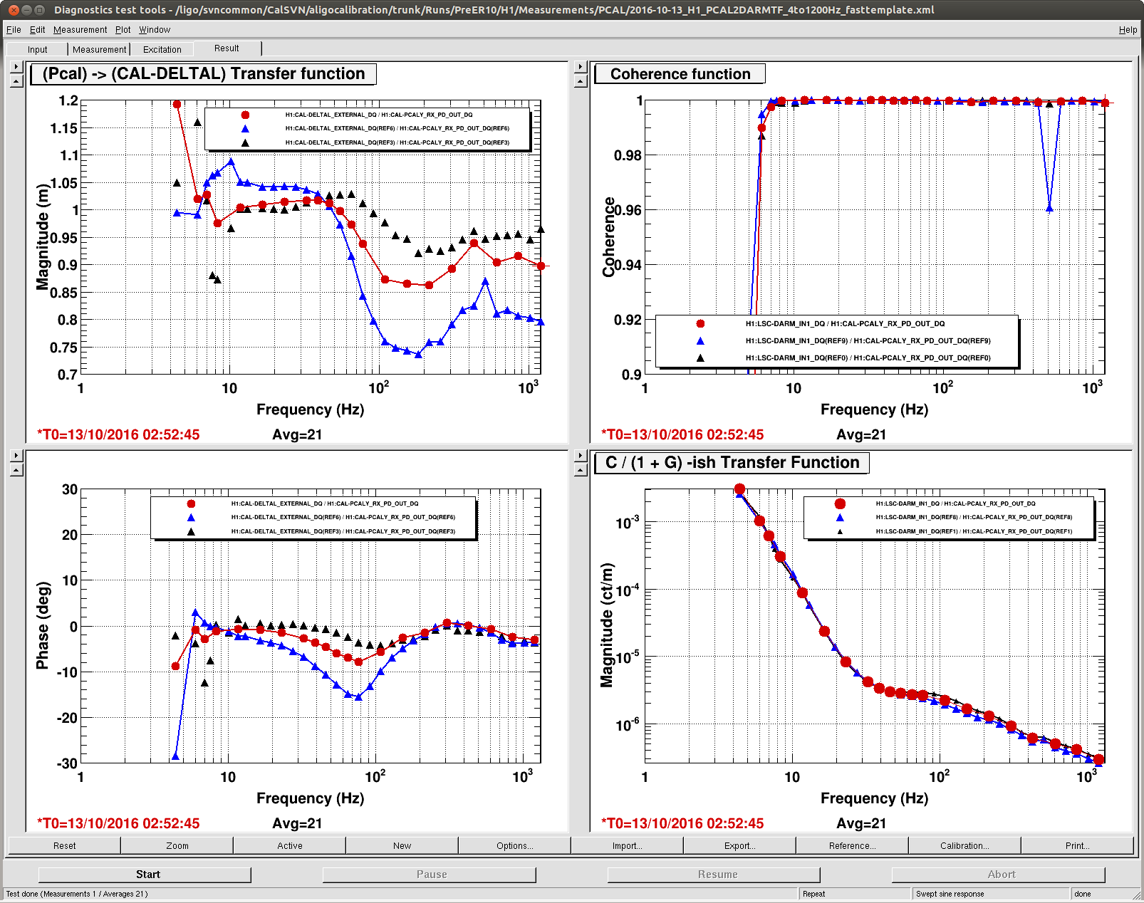
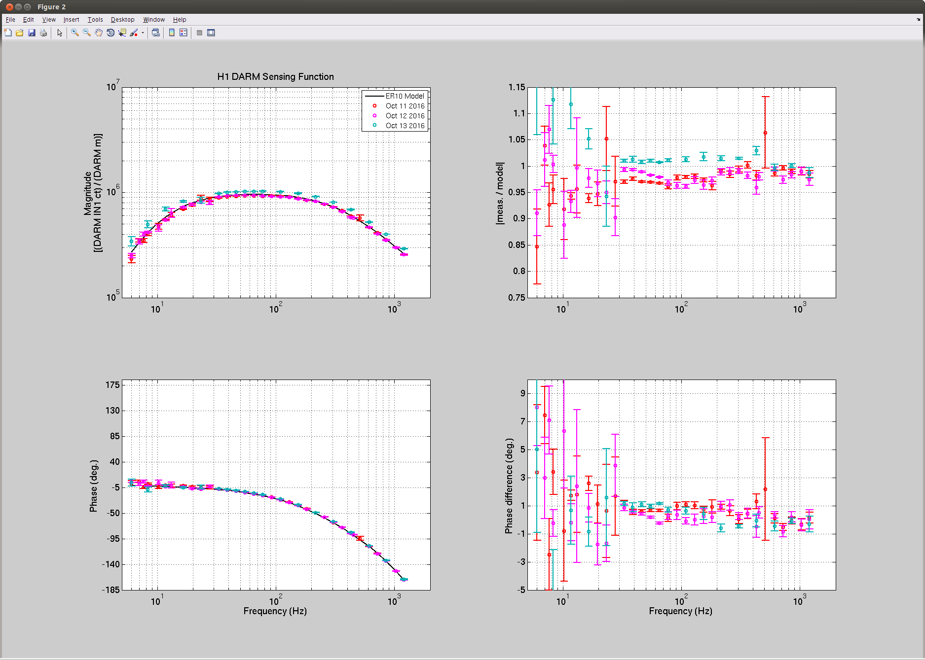
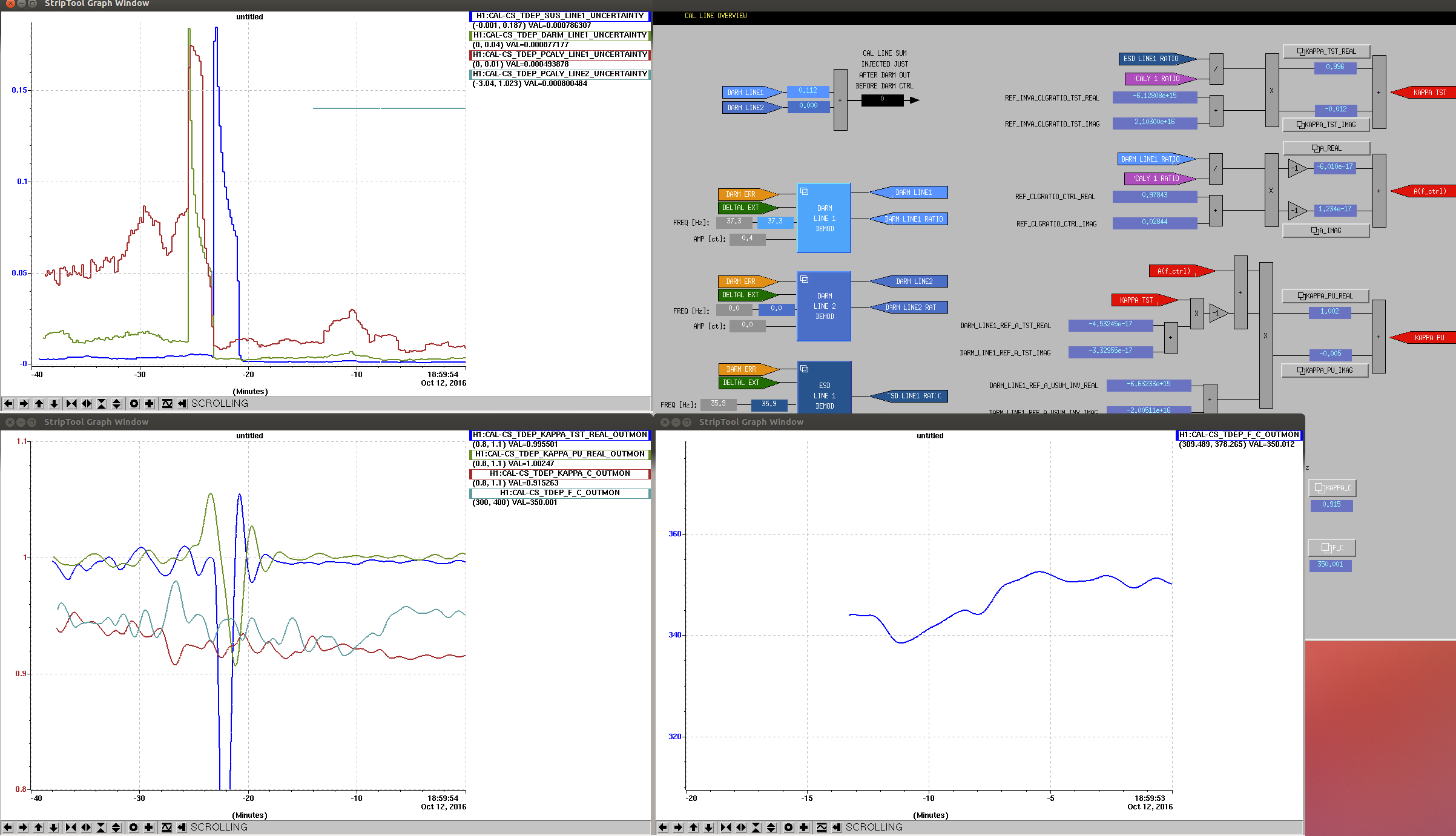
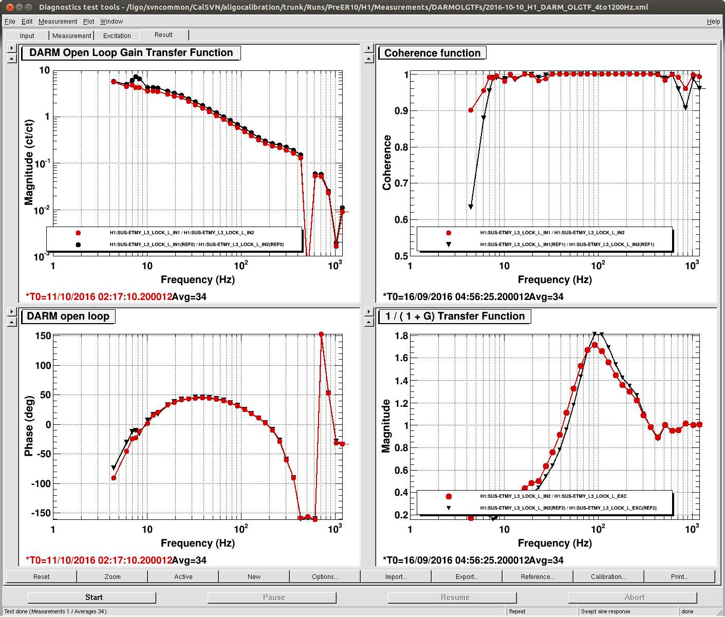
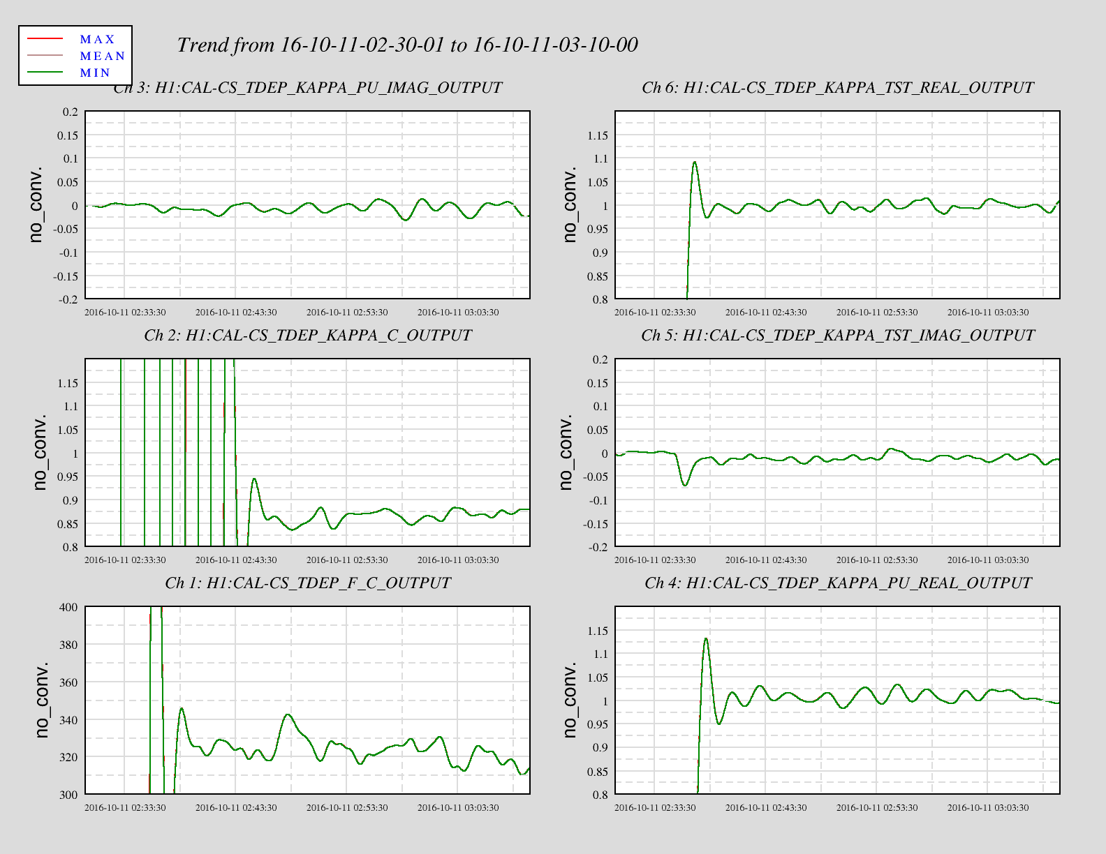
In the end, the power recycling gain is about 31.2, whereas it used to be about 29.5 in NomLowNoise before this work. Also, as Jeff points out in alog 30481, it looks like this did good things for the DARM cavity pole and the optical gain.
At about 06:49:15 UTC, I had just about the lowest value for the broad peak at about 440 Hz. Going back to the offsets I had at the time did not reproduce that low of a peak though and the recycling gain wasn't at its maximum, so I ended up sticking with the offsets that maximized the power recycling gain. I may go back and look at the alignment of all the optics at that time to see if there was anything drastically different.
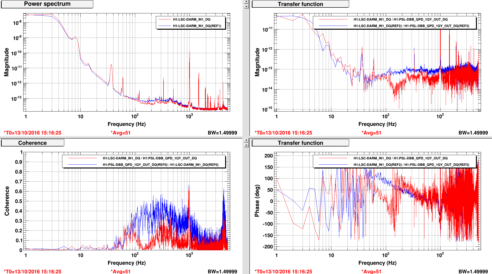
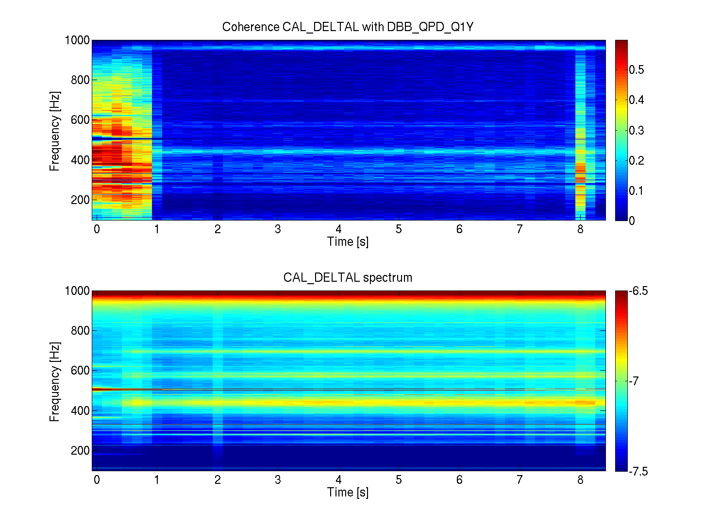
I also turned back on Gabriele's Jitter feedforward with the same gain of -1, and it still seems to be doing quite well. I haven't looked at the coherence, so I don't know if this is quite as good as when he and I were tuning it earlier today, but it still made a significant improvement in the 80 Hz - 250+ Hz region. I have this feedforward turning off in the Down state of the ISC_LOCK guardian, but it must still be turned on by hand. Once we're satisfied that it does good consistently, we can add it to NoiseTunings.
For now, I'm leaving the POP_A offsets in place, but the SOFT offsets will be turned off upon lockloss. I want to make sure that including them during the acquisition sequence isn't harmful to lock acquisition before accepting them permanently. I'm hoping though that they're fine, so that the ASC will handle all the SRM moving and we don't have to do anything by hand. To be checked tomorrow.
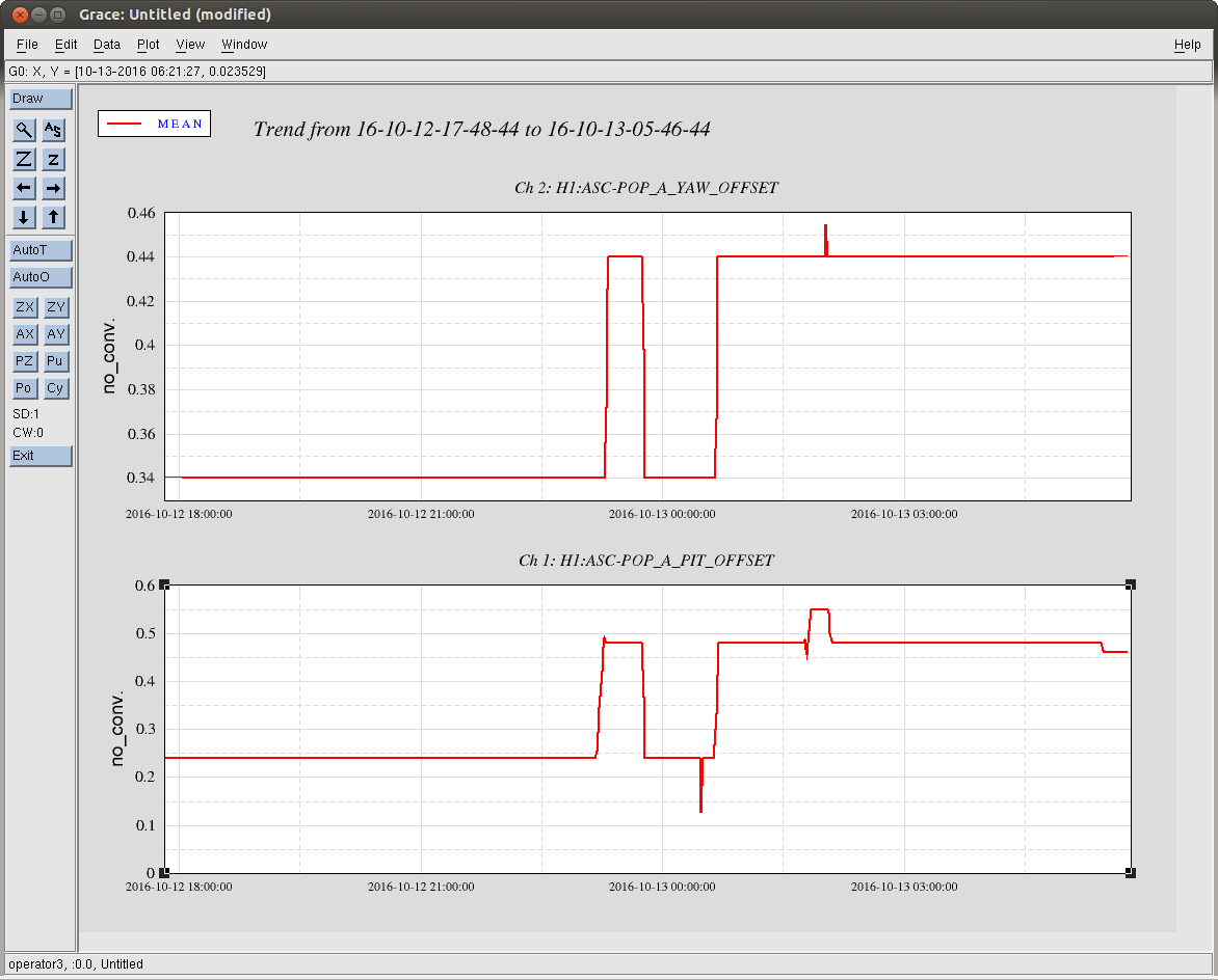
Offsets that I like in the end are:
-
POP_A_P: 0.52
-
POP_A_Y: 0.44
-
DSOFT_P: 0.00
-
DSOFT_Y: 0.04
-
CSOFT_P: 0.06
-
CSOFT_Y: -0.04
Ideas:
-
A2L for recycling cavity optics
-
Re-look for SRM ASC error signal - maybe there's a bit more hope if the overall IFO alignment is better?


