Elli (remotely), Kiwamu,
This morning was a morning for another measurement of the SRC gouy phase. As opposed to the single bounce measurements done yesterday, we proceeded to a round trip beam measurement.
I wanted to measure two different configurations as instructed by Elli, but I could get only one of them done today. We will spend (at least) another morning to measure the other configuration.
[Some background]
A trick in this whole series of measurements is that one can effectively cancel the effect of the output optical train (i.e. the optical path from SRM all the way to the setup on ISCT6 which is not easy to precisely characterize) by having measurements of single bounce and round trip beams. The round trip beam we mean here is a beam that bounces around the signal recycling cavity only once and comes out to the AS port. We have finished the single bounce measurement yesterday, and therefore the next step today was to measure the round trip beam.
[The setup]
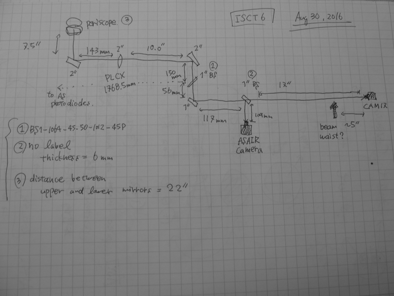
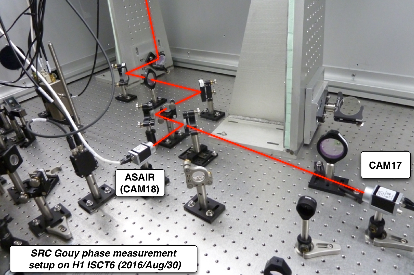
I added an extra component to ISCT6. It is a beam blocking object. Everything else was unchanged on ISCT6. See the picture of the setup shown below.
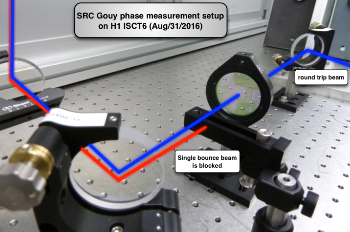
The blocking object (a black rectangular piece in the middle) is dedicated to block the single bounce beam which would cause undesired interference with the round trip beam. To split the beam into single and round trip beams, I introduced an intentional misalignment in SRM by 700 urad in pitch as suggested by Elli. In addition, I found that the separation of the two beams became even better with additional misalignment (~ 100 urad) in pitch of PR2 as well. This misaligned configuration is one of two configurations we wanted to test. The other configuration will introduce misalignment in another combination of optics, ITM and IM4, instead of SRM.
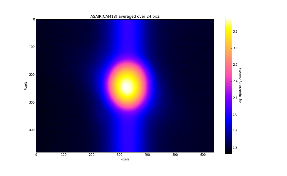
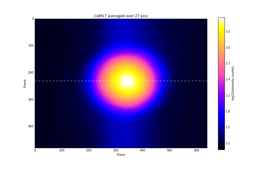
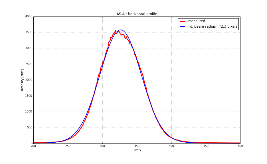
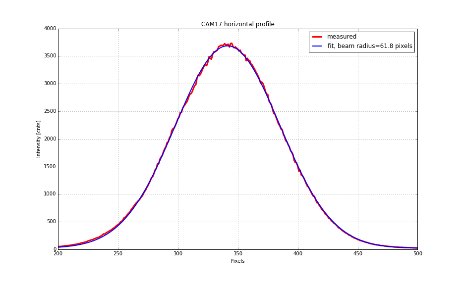
As I introduced misalignment in SRM, it made a clean beam separation on CAM17 (see the previous log) while ASAIR did not as expected. I manually steered a mirror and beam splitter that were in front of the cameras to center the round trip beam on both cameras. The blocking object was removed when I finished the measurement this morning.
- - - - some other settings.
PSL power into IMC = 25 W
ITMY ring heater = 0.5 W (0.25 W for upper and lower segments each)
CO2Y = 286 mW
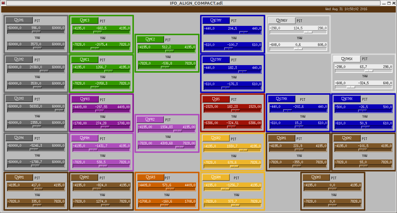
The interferometer configuration = single bounce (with ITMY aligned) + SRM almost aligned (see the second and third attachment for the specific alignment values)
The camera settings = same as the previous measurements (alog 29389)
ASAIR exposure time = 4400 usec
CAM17 exposure time = 7000 usec
[The measurement]
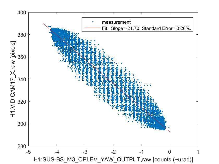
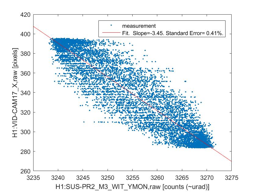
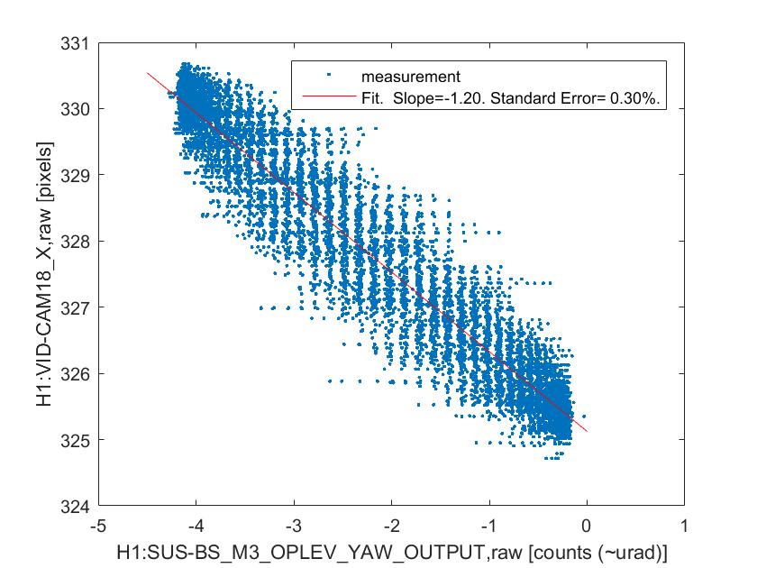
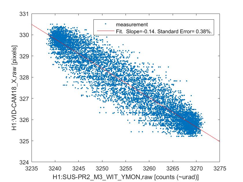
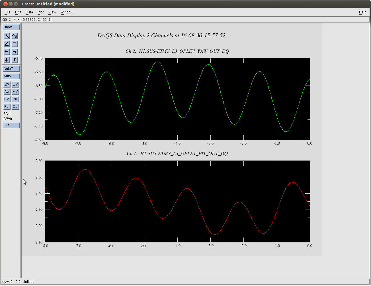
The measurement itself is the same as what we did yesterday -- excite BS or PR2 in yaw at a certain frequency and measure the centroid positions on the two gigE cameras. I ended up doing four sets of measurements as described below because I was worried that a high excitation may have introduced a large enough clipping somewhere which may confuse the later analysis. By the way, later Jenne told me that there were some angular excitation signals unintentionally left on throughout the measurements on BS and all the SR mirrors (in both pitch and yaw) at frequencies around 20 Hz, which I don't think an issue because they are small compared to my measurement excitation and also the frequencies are different than my excitation.
- measurement #1
18:06:40 - 18:16:40 UTC
BS yaw excitation by 6 urad at 0.2 Hz (ASAIR camera showed a clipping-type behavior)
- measurement #2
18:19:53 - 18:29:53 UTC
BS yaw excitation by 3 urad at 0.2 Hz
- measurement #3
18:34:15 - 18:44:15 UTC
PR2 yaw excitation by 20 urad at 0.2 Hz (ASAIR camera showed a clipping-type behavior)
- measurement #4
18:47:15 - 18:57:15 UTC
PR2 yaw excitation by 10 urad at 0.2 Hz
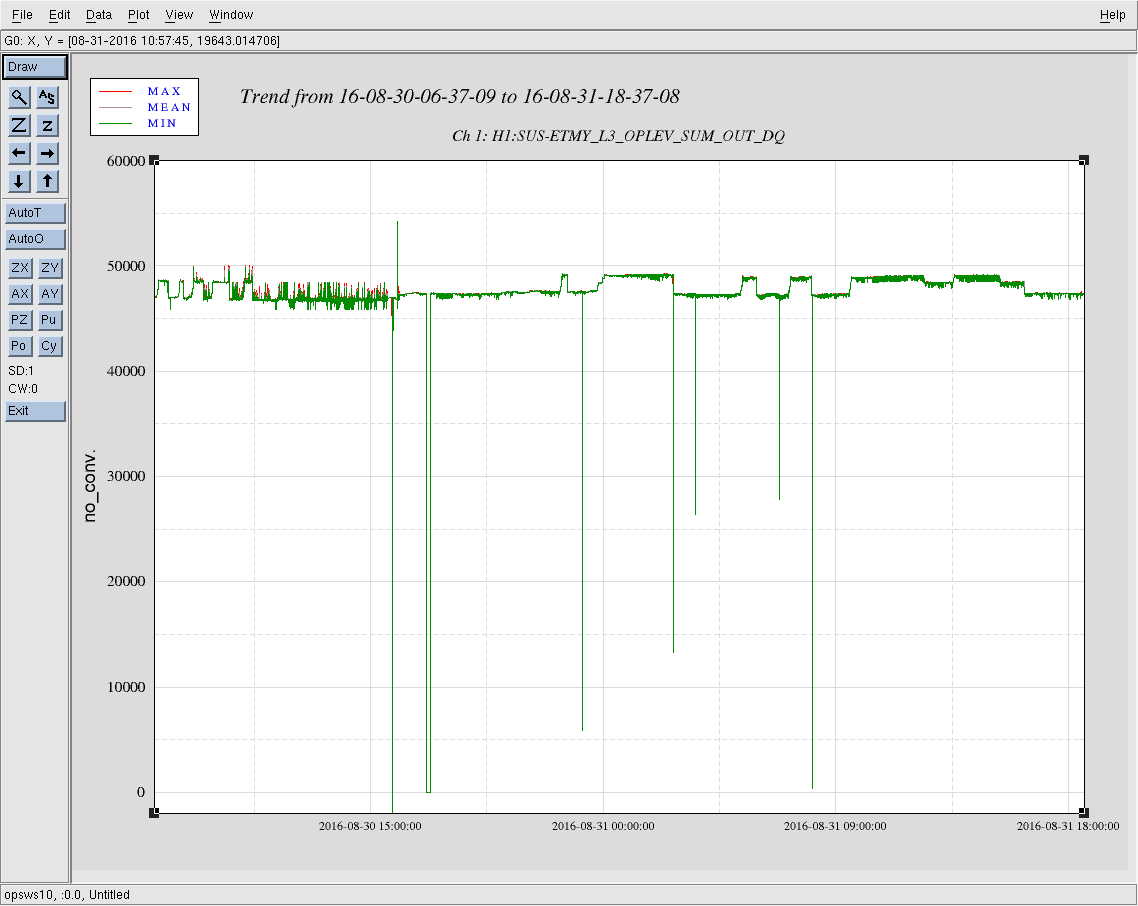
[The data]
A thorough analysis will be remotely performed by Elli. The data are saved in kiwamu.izumi/Public/measurements/20160831_SRCgouy2/data1