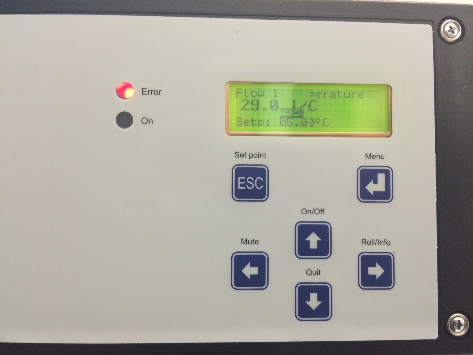
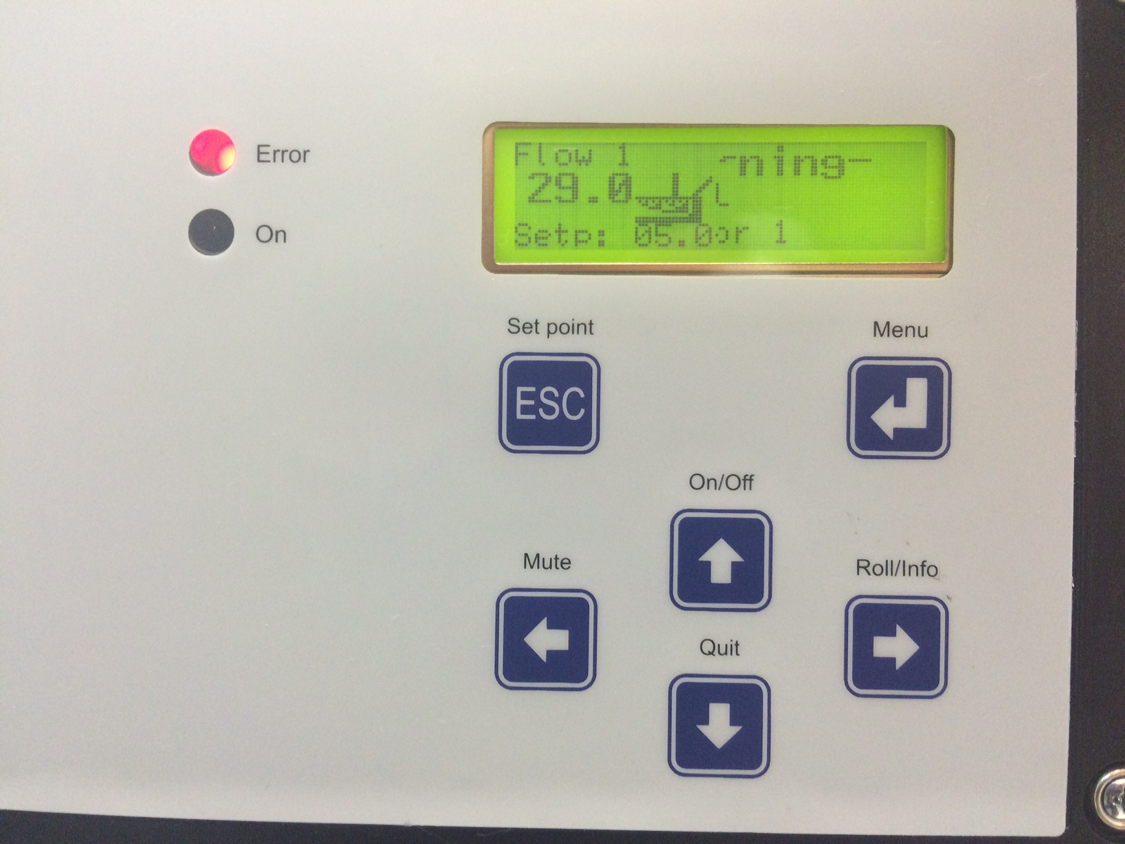
Displaying reports 61561-61580 of 77273.Go to page Start 3075 3076 3077 3078 3079 3080 3081 3082 3083 End
Reports until 20:22, Monday 19 January 2015
H1 ISC
evan.hall@LIGO.ORG - posted 20:22, Monday 19 January 2015 (16148)
ALS DIFF and COMM just fine with ETMX ESD linearization

Alexa, Sheila, Evan

After damping down the ETMX bounce mode, we proceeded to turn on the ETMX ESD linearization. Both with and without this linearization, DIFF and COMM appear to be able to hold indefinitely, so at the very least, having the linearization on appears to have no adverse effect on locking. But just so there's no surprises, we've turned it off for now.

H1 ISC
koji.arai@LIGO.ORG - posted 18:19, Monday 19 January 2015 (16145)
Sunday OMC work report

Dan, Koji

We came in on Sunday and worked on several measurements on the OMC.

1) OMC breadboard mode

In the measurement the other day, we observed the forest of the peaks beween 400 and 1.3kHz.
There should be a peak from the OMC glass breadboard. We tried to identify the mode by exciting
the OMC SUS. We did not find any clear sign of the resonance below 990Hz, which was the frequency
limit of the excitation in the OMC SUS model. There is some possibility that the mode exist at higer frequency.
The experiment at Caltech showed the resonance at 1.1kHz with some different boundary condition.

We also tried to replicate the noise structure by shaking the vertical motion of the OMC SUS. This was
not successfull as Zach indicated before.

2) Effect of the OMC ASC noise

The OMC ASC control was done by the OMC QPDs. We checked if turning off the servo cause any improvement
or deterioration of the OMC length noise. We observed no difference in the half fringe spectrum of the OMC length noise.

Right now the OMC dither alignment control is not functional partly because of degraded RIN of the IMC trans.
The RIN of the IMC transmitted beam was 10-5 to 10-6. There was modification of the IMC WFS servo recently, and
this might be the reason.

We also checked if we can see any OMC length noise by injecting a peak in the OMC tip-tilt angles. There is some coupling
but the result was not so conclusive.

3) Direct measurement of the OMC PZT driver noise

In order to try to pin down the actuator noise contribution in the OMC length spectrum, the outputs of the PZT driver
were measured. First of all, the HV power supply voltage was reduced from 100V to 10V for safety. A DB25 breakout was
inserted at the PZT driver output so that we could measure the voltages across the PZTs. The measurement result is going
to be summarized in another alog entry.

The output of the HV voltage supply was restored to 100V after the measurement.

H1 ISC (ISC, SUS)
evan.hall@LIGO.ORG - posted 16:22, Monday 19 January 2015 (16143)
ETMX bounce mode damping

Sheila, Alexa, Evan

For a few hours today, ALS DIFF locking was blocked by the appearance of the 9.8 Hz ETMX bounce mode. We used the procedure in LHO#15247 to damp it. We let it damp for about an hour, and then proceeded with locking activity.

In the attached plot, blue and red are before and after damping, respectively.

Non-image files attached to this report
H1 CDS
david.barker@LIGO.ORG - posted 15:04, Monday 19 January 2015 - last comment - 09:41, Tuesday 20 January 2015(16142)
Tracking ADC errors on IOP models

We are tracking the ADC errors which are being seen on the STATE_WORD for the IOP models. These are a feature RCG2.9 They are raised very infrequently, work to remove them is ongoing.

I have cleared the errors by pressing the DIAG RESET buttons on the IOP models. Here is the maximum ADC0 hold time for the models which were showing the error:

h1iopsusb123: adcHoldTimeEverMax=23, adcHoldTimeEverMaxWhen=1105450127 (Jan 16 2015 13:28:31 UTC)

h1iopsush34: adcHoldTimeEverMax=25, adcHoldTimeEverMaxWhen=1105533748 (Jan 17 2015 12:42:12 UTC)

h1iopsush56: adcHoldTimeEverMax=24, adcHoldTimeEverMaxWhen=1105583419 (Jan 18 2015 02:30:03 UTC)

h1iopsusey: adcHoldTimeEverMax=21, adcHoldTimeEverMaxWhen=1105219714 (Jan 13 2015 21:28:18 UTC)

h1iopslc0: adcHoldTimeEverMax=22, adcHoldTimeEverMaxWhen=1105241179 (Jan 14 2015 03:26:03 UTC)

Comments related to this report
keith.thorne@LIGO.ORG - 09:41, Tuesday 20 January 2015 (16151)CDS
See more complete L1 data at aLOG entry 16455.  We need a bit more proc file data to characterize the limits
H1 CDS (DAQ)
david.barker@LIGO.ORG - posted 14:25, Monday 19 January 2015 (16140)
CDS model and DAQ restart report, Saturday and Sunday 17th,18th January 2015

model restarts logged for Sat 17/Jan/2015
2015_01_17 07:40 h1fw0
2015_01_17 08:06 h1fw0
2015_01_17 10:12 h1fw0
2015_01_17 10:30 h1fw1
2015_01_17 11:34 h1fw1
2015_01_17 15:07 h1fw1
2015_01_17 15:33 h1fw1
2015_01_17 22:17 h1fw0

model restarts logged for Sun 18/Jan/2015
2015_01_18 03:02 h1fw0
2015_01_18 20:26 h1fw1

all unexpected restarts. We will try power cycling the solaris QFS writers Tuesday to see if this improves the situation.

Conlog frequently changing channels log files attached.

Non-image files attached to this report
H1 AOS
sheila.dwyer@LIGO.ORG - posted 13:02, Monday 19 January 2015 - last comment - 17:21, Monday 19 January 2015(16139)
DRMI ASC

Alexa, Evan, Sheila

We have a DRMI ASC cnfiguration in the guardian that seems good enough for now.  We have PRC2 (REFLB 9I to PR3), SRC1 (combination of AS 36 WFS to SR3),  SRC2 (combination of AS_C to SRM and SR2) with low bandwidth, and MICH (AS A 36 combination) to BS, oplev damping off. 

We have also edited the offloading in the guardian, so that we have a 20 second ramp time and we leave the loops running.  This works now.  

Comments related to this report
alexan.staley@LIGO.ORG - 17:21, Monday 19 January 2015 (16144)

Just to clarify, the BS IS running at high BW, unlike the rest of the loops.

H1 IOO
sheila.dwyer@LIGO.ORG - posted 12:05, Monday 19 January 2015 - last comment - 09:43, Tuesday 20 January 2015(16138)
IMC ASC DOF4

We have had several incidents where MC1+MC3 trip, and sometimes also cause HAM2 ISI to trip.  Kiwamu found that there were large signals coming through DOF4 (16128), although there was some other underlying problem which was causing MC2 to get large length signals. 

We Had DOF 4 off for most of the day saturday, once we found and fixed the PSL noise eater oscillation we turned it back on.  This morning we dropped the mode cleaner lock when we were attempting to lock the X arm in IR, which also tripped MC1, MC3, and HAM2 ISI (this lockloss is the kind of thing that is expected to happen once in a while, and should not cause a cascade of trips).  We have again held the offsets on DOF 4,  because somehow this loop makes the sysem more fragile.  Since holding the outputs we have had several mode cleaner lock losses without any trips.  

Comments related to this report
suresh.doravari@LIGO.ORG - 09:43, Tuesday 20 January 2015 (16152)


Perhaps it is worth while going through the WFS alignment process once.  The most likely scenario is that the WFS_B_DC_PIT and YAW offsets were turned on while the spots were centered.  I am sure the following steps are obvious but let me put them down here any way for future reference:

Procedure to center the direct reflection from the IMC on the WFS sensors:

1) Start with a good alignment of the IMC input beam.  Off load any offsets from the suspensions.  Maximise IMC output by hand if necessary.

2) Unlock the mode cleaner by invoking the "Down" state in the IMC Guardian

3) Using the MC2 Alignment sliders misalign the MC2 by a milliradian or so in pitch till the IMC stops flashing. (Use StripTool)

4) Open the WFS DC screens and inside that open the WFS_A and WFS B_PIT and YAW filter banks.  Switch off any offsets that may be present.

5) Using the IMC WFS picomotors center the direct reflection spots on the WFS A and WFS B.

6) Switch off the DOF4 inputs in YAW and PIT.  Make sure that the history is cleared and that all servo outputs are zeroed.

(At this stage we have ensured that  the gaussian sidebands (24MHz) are centered on the WFS sensors)

Now we start setting up the DOF4 servos:

7) Bring the MC2 Back into alignment.  Note that there is a wait time of several minutes before the top stage of the MC2 moves into place.  There is a long time constant low pass filter on the alignments sliders

8) Due to some hysteresis somewhere,  you may need to search for good high intensity flashes.  They will be within a few tens of microrads from the previous setting.  (StripTool)

9) Bring the IMC back to "LOCKED" state in IMC Guardian.  Keep the DOF4 loops off at this stage.

10) As the mode cleaner alignment loops (DOF1,2,3) work the reflected field is extinguished and some wierd pattern develops in the IMC REFL camera.  This will take about 3 to 5 mins or so.

11) This wierd shape causes a spurious offset to appear on the WFS_A and WFS_B DC signals. 

12) Zero these signals using the offsets in the WFS_DC PIT and YAW filter banks.

13) If everything is stable switch on the DOF4 filter bank inputs.

14) Keep track of the DOF4 outputs.  They should not be monotonously building up to values larger than a few tens.   If they cross 100 then something is misaligned.

15) Currently DOF4 uses WFS_B. WFS_A serves as an out of loop sensor.  Trend the WFS_A PIT and YAW after a day and see if there is any drastic change.  It indicates a drifting alignment causing an evolving IMC REFL pattern.  Not great news but not a deal breaker either.  As long as it is not monotonously running away to values outside [-0.25, +0.25] it should be okay.

H1 ISC
evan.hall@LIGO.ORG - posted 22:42, Saturday 17 January 2015 (16134)
DRMI3f+arms

Alexa, Sheila, Dan, Evan

With the COMM PLL locking robustly again, we have been able to proceed with little trouble to DRMI3f with arms held off resonance. We then tried to proceed further by letting the ISC_LOCK guardian transition the CARM sensor from ALS COMM to sqrt(TRX+TRY), but this blew the lock. So we will have to diagnose the transition sequence more carefully.

DRMI ASC with arms off resonance continues to be fragile. We already know that the PRCL loops require careful tuning of the pointing onto the POP QPDs in order to function. But tonight, even the MICH and SRCL loops would blow the lock when the guardian turned them on.

H1 ISC
daniel.hoak@LIGO.ORG - posted 22:42, Saturday 17 January 2015 (16133)
Measurement running overnight

Alexa and I have left a measurement running on the IMC overnight.

Koji and I will be in tomorrow to work on the OMC, I will clean up after the measurement in the morning.

H1 PSL (IOO, ISC, PSL)
sheila.dwyer@LIGO.ORG - posted 20:17, Saturday 17 January 2015 - last comment - 21:05, Tuesday 20 January 2015(16132)
PSL Noise eater oscillation

Alexa, Evan, Dan, Sheila

We have been having intermittent problems for the last two or three days.  This evening we traced the problems we've been having with ALS COMM (alog 16129 ) to an oscillation of the PSL noise eater.  The tell tale symptom was amplitude noise at around 900 kHz on the PSL light.  We don't know of a good indicator of this problem from the control room.

We do not know if this was the cause of our mode cleaner lock losses over the last few days (alog 16128 ),  or to tripping of MC1+MC3 suspensions and HAM2 ISI.  

After I toggled the noise eater switch the ISS first loop was unable to lock.  For now we have turned it off. 

We had the outputs held on the IMC WFS DOF4 from late last night until 8 pm today. We didn't see any trips of MC1+MC3 today.  Now we have turned DOF4 back on.

Comments related to this report
koji.arai@LIGO.ORG - 11:43, Sunday 18 January 2015 (16135)

I turned on the ISS first loop. For the OMC characteization, we needed some kind of ISS.

1. Changed REFSIGNAL (H1:PSL-ISS_REFSIGNAL) from -2.248 to -2.135 to match it with H1:PSL-ISS_PDA_AVG
2. Push "On" of AUTOLOCK

This allowed me to engage the ISS loop. The out of loop "lsd" monitor (H1:PSL-ISS_PDB_LSD) shows 1.2e-8/rtHz.

rana.adhikari@LIGO.ORG - 17:58, Sunday 18 January 2015 (16136)

There was recent check of the Noise Eater mon at LLO (log 13353). Wasn't that useful, but the binary NE mon is supposed to tell us when the NE loop is oscillating.

There were also numerous instances of this during eLIGO; the 'solution' then was to turn the servo OFF and then ON. Maybe if the monitor is now mistuned, we should adjust the resonant circuit to operate at 900 kHz.

sheila.dwyer@LIGO.ORG - 11:43, Monday 19 January 2015 (16137)DetChar

Apparently we do have at least two ways to tell this is happenening from the control room, which means we could have some automated error checking for it.  

First, this was already done in the PSL ODC, which seems to have degraded at least at LHO.  (alog 9674)  The PSL ODC screen now looks like the attached screen shot, I don't know what hapened to it but it might be helpfull to restore it.  

The second screenshot shows that the RF mon on the COMM PFD was around -1dBm even when the X arm was unlocked while the noise eater was oscillating.  We can add an error check for this in the COMM PLL beckhoff code.  This is similar to what we did for the end station lasers (alog 10273 )

Images attached to this comment
rana.adhikari@LIGO.ORG - 21:05, Tuesday 20 January 2015 (16172)DetChar, PSL

The attached plots show 2 weeks of the PSL Noise Eater channels as well as the ALS COMM demod mon.

NPRO_NEMON doesn't show any change and I don't know what it is connected to.

NPRO_RRO is the binary indicator of whether the NPRO Relaxation Relaxation Oscillation monitor is indicating a high noise state: around -5800 means OK, around -300 means Oscillating.

COMM DEMOD RFMON shows the non-bandpassed RF noise (in units of dBm):

-35 dBm corresponds to the bare noise on the laser without the arms locked

-1 dBm seems to be what we see with the arms unlocked an the NPRO NE oscillating

+5 dBm corresponds to the X arm locked and there's a good beat note between the green PSL and the green X trans beam


* the RRO indicator on the PSL screen had the threshold set too high; I've changed it to now change from green to red at -2000 counts rather than -200 (which would make it always show GREEN)

Images attached to this comment
H1 CDS (DAQ)
david.barker@LIGO.ORG - posted 09:00, Saturday 17 January 2015 - last comment - 14:38, Monday 19 January 2015(16130)
CDS model and DAQ restart report, Friday 16th January 2015

model restarts logged for Fri 16/Jan/2015
2015_01_16 09:43 h1fw0
2015_01_16 19:03 h1fw0
2015_01_16 20:27 h1fw1

all unexpected restarts. Conlog frequently changing channels list attached.

Non-image files attached to this report
Comments related to this report
david.barker@LIGO.ORG - 14:38, Monday 19 January 2015 (16141)

Y1PLC2 13:07 1/16 2015

H1 ISC
evan.hall@LIGO.ORG - posted 21:03, Friday 16 January 2015 - last comment - 09:45, Saturday 17 January 2015(16129)
Bad IMC, bad COMM PLL

Alexa, Sheila, Kiwamu, Evan

Tonight we hoped to proceed further with the full locking procedure.

Unforunately, we have been stymied by repeated MC1/MC3 trips described in LHO#16128, and frequent unlocking of the modecleaner.

Eventually we noticed that some of these unlocking events were correlated with our attempts to lock ALS COMM. Sheila went out to check the IMC PDH loop, but found it is healthy, with a 28 kHz UGF with 40 degrees of phase.

Next, we noticed that even when the IMC stayed locked, ALS COMM would not lock. Sheila went out into the LVEA to check the health of COMM, and found that the PLL was not even locking (despite the digital system reporting that it was locked). Eventually, we shifted over the COMM signals from the COMM PFD to the DIFF PFD, and we were able to get COMM locked. We thought this meant that the COMM PFD was broken, but when we plugged the COMM signals back into the COMM PFD, we could get COMM to lock as well. Loose connection? Badly crimped cable? Unclear.

The following UTC times give some MC1/MC3 trips:

Comments related to this report
alexan.staley@LIGO.ORG - 09:45, Saturday 17 January 2015 (16131)

We also caused HAM2 HEPI to trip several times. I had to adjust PR3 alignment to get the COMM and DIFF beatnotes back to a nominal value. These new alignment positions have not been saved yet.

H1 IOO (ISC)
kiwamu.izumi@LIGO.ORG - posted 19:16, Friday 16 January 2015 (16128)
IMC mysterious unlock and tripping events

Sheila told me that there were two kinds of mysterious events in IMC

  1. IMC unlocked during ALS diff
  2. MC1 and MC3 suspensions tripped for some reason

So I looked into these two kinds of incidents. Here is a summary of my understanding of what were happening, although they are not 100% understood yet.


(IMC unlocking events)

This was due to saturation in the longitudinal drive at the M3 stage of the MC2 suspension. I picked up two unlocking events from this after noon at  around 22:24 and 22:53 UTC respectively. Both unlocking events were caused by saturation in the M3 stage of the MC2 suspension. I attach a screenshot of the lockloss analyzer for the 2nd event:

In the upper right panel of the attached lock loss, it is clearly seen that the M3 longitudinal drive hit the limiter (which had been set to be close to the DAC saturation counts). According to T1300079-v2, the range of the M3 stage is about 0.5 um in peak. Therefore, roughly speaking, the IMC cavity must have moved more than 0.5 um in order to saturate the DACs.

On the other hand, we have no idea of why the IMC length motion (or perhaps PSL frequency) moved by such amount on a time scal of 200 msec or so.

We switched the coil driver setting to "Acq on, LP off" to see if it helps, but we then had another incident which was also caused by the same issue. We then turn them back into the low noise mode i.e. state request=1.

(MC1 and 3 tripping)

At the beggining, I was imagining that the MC1 and MC3 suspensions were kicked by the ASC loops right after the IMC unlocked. However, carefully looking into them, I found that they tripped some times after a lock loss. In a case, they tripped ~40 seconds after the lock loss event at around 22:53 UTC. According to various IMC ASC data, it seems that DOF4 gave a huge impulse (~107 cnts ! ) to the MC1 and MC3 suspensions. This happened when the IMC LOCK guardian catched a fringe and hence a high build up. See the attached below:

It looks as if the DOF4 maintained a large number during they were off and then released it when the ASC was triggered. A strange point is that any of the IMC ASC loops, including this DOF4, should not maintain the past values as all the intergrators are cleared by the filter trigger in every lock loss. We double-checked the history handling of the integrators in foton, but they were set right -- no history maintained. Also, we reloaded the latest filters in order to be 100% sure that the filters in the front end are actually the ones in the latest foton file.

P.S.

We hoped that the issue would be gone by loading the latest foton file, but it seems to still persist. We had another incident where the MC1 and MC3 suspensions were tripped again when the IMC lost the lock. The lock loss was initated by saturation in the M3 stage of the MC2 suspension. Almost at the same time as the lock loss, the DOF4 kicked the MC1 and MC3 suspensions again. Hmmmm.... We need to further investigate this issue.

Images attached to this report
H1 ISC
koji.arai@LIGO.ORG - posted 14:27, Thursday 15 January 2015 - last comment - 18:29, Monday 19 January 2015(16089)
H1 OMC cavity length noise measurement with PDH locking

[Koji, Dan]

This is a followup entry for LHO ALOG 16034.

Summary

- The OMC cavity was locked with PDH locking by implementing a bypass optical path from at the OMC REFL to the AS resonant RF PD.
- The OMC cavity length displacement was measured. It is found in the 4th attachment.
- It is mostly consistent with Zach’s measurement LLO ALOG 8674 and has x3 better floor level at some frequencies.
- There is a forest of peaks above 400Hz to 1.3kHz. They were very easily excited by light tapping on the HEPI crossbars


Motivation

- The length noise of the Output Mode Cleaners at LHO and LLO were so far locked with the transmission DCPDs with length dither or mid fringe with CDS.
- The measurement bandwidth with these techniques was limited by the CDS bandwidth (8kHz) or the dither frequency (2~3kHz). The cavity length noise above these frequencies wer e unknown.
- The measurements were also prone to the intensity noise on the beam. As the base band is at audio frequency in either cases, it is hard to be shot noise limited without proper setting of the intensity stabilization. Some features in the spectrum were not distinguishable from the intensity noise.

- PDH locking of the OMC was expected to provide an independent measurement of the OMC length noise with possibly better sensitivity, as the PDH locking is in principle insensitive to the intensity noise.
- In fact, the most of the conmponents for the PDH locking were already there. If we use the single bounce beam from one of the ITMs, the beam is already phase modulated. An RF PD is at the same table with the OMC REFL beam. The detection system and actuator are on the field racks next to HAM6. Therefore the effort of the PDH locking was minimal.

Configuration

- The ITMY single bounce beam was guided to the OMC. i.e PRM/SRM/ITMX/ETMX/ETMY were misaligned.
- The beam alignment to the OMC was controlled using OMC QPDs. The dither alignment servo has not been configured and was not functional at the time.
- The OMC REFL beam was aligned to the OMCR path on ISCT6 by moving an in-vacuum picomotor as Dan described as Dan described.

- The OMCR beam was introduced to ASAIR_A PD without moving existing optics on the table. As found in the figure (attachment 1), an additional optical path was added to the OMCR path. The OMCR beam was deflected between two lenses and brought to AS45 PD going through the space between the mirrors in the AS path. The beam on the PD was focused by a lens with the focal length of 150mm. This made the spot sufficiently small for the 2mm aperture of the PD.

- With the single bounce configuration, the optical power from the chamber was ~10mW.

- The servo configuration is found in the figure (attachment 2). The AS 45MHz demodulator was used for the PDH sensing (i.e. no rewiring was necessary). We found our bad luck that the proper demodulation phase was about 45 deg off and the signal size in the I and Q phases were almost the same with opposite sign. This meant that we could combine these two with another SR560. But we decided to use the I signal for the error signal.

- Since there is no digital signal path from LSC outputs to the OMC PZT, we implemented an analog servo. The error signal from the demodulator I-phase monitor channel was fed to an SR560 with gain of -2 and LPF (-16dB/Oct, fc=300Hz). The 50 Ohm output of this SR560 was fed to another SR560 with the gain of the unity. The second SR560 was used as a summing point for an openloop TF measurement. The 50Ohm output of the second SR560 was connected to an aux drive port of the HV driver.

Servo modeling

- You may wonder how just a 300Hz 2nd order LPF could make the servo stable!? In fact, we could lock the cavity even with gain of -1 with flat response. This is a subtle combination of the dewhitening and the poles and zeros formed by the PZT capacitance and the output RC network of the driver.

- The open loop transfer function of the servo was measured (attachment 3) by injecting the excitation at the second SR560 while the "after sum" (denominator) and "before sum" (numerator) signals were observed with SR785.

- Driver/actuator response: The HV Piezo driver (D060283) has two dewhitening stages and an output RC network. The dewhitening stage, which are common for the digital and external analog inputs, have two poles at 0.923Hz and two zeros at 10.15Hz with the DC gain of the unity. Note that the signal is reduced by a factor of 0.9989, as the input impedance of the driver (47.5kOhm) and the 50Ohm output impedance of the SR560 form a voltage divider. The main HV stage has the gain of 10. The output stage has the output series resister of 50k (R51) and then the parallel capacitors including the PZT capacitance of 0.51uF (Noliac NAC2124). (C11 - 0.47uF // C26+R55 - 0.47uF // Cpzt - 0.51uF). This imposes two poles at 2.19Hz and 502.1Hz, and one zero at 338.6Hz. Finally the OMC PZT2 has the calibration of 12.9nm/V (measured at Caltech), and the beam incident angle of theta = 4.04deg, and parasitic mechanical resonance of the PZT tombstone (pole at 9.5kHz Q=100 and zero at 11kHz Q=100). Don't forget that the factor of 2 i.e. cavity length change = 2/cos(theta) * PZT displacement

- The model of the openloop transfer function agrees exteremely well with the measurement. From this model, we determined the slope of the PDH signal to be 4.0e9 V/m.

Cavity displacemen noise

- Calibrated cavity displacement noise is found in attachment 4.
- The red curve is the error signal calibrated in the unit of displacement. The compensation of the loop supression was applied to this red curve in order to obatin the "estimated free running motion" of the cavity (Blue curve).
- The estimated cavity displacement seems to have better floor level by a factor ~3 compared to the half-fringe measurement at LLO. Also the spectrum below 300Hz looks cleaner and smoother. We wonder what is the cause of this noise.
- Similar to the LLO measurement, the spectrum has forest of peaks from 400Hz to 1.3kHz. There is very eminent peak at 9.5kHz which is associated with the prism resonances of the cavity.

- The dark noise was estimated to be 3.3x10⁻¹⁷m/rtHz. I made the simplest estimation of the shot noise level. The dark noise was assumed to be limited by the PD noise. The shot noise intercept current is 2mA and the photocurrent was ~8mA. Therefore the shot noise level was estimated to be 3.3x10⁻¹⁷x Sqrt(8/2) = 6.6x10⁻¹⁷ m/rtHz.

Peaks between 400Hz and 1.3kHz

- It is unlikely that the OMC cavity itself has such many mechanical resonances from 400Hz to 1.3kHz. It is known that the OMC cavity has one high Q resonance at 1kHz (body bending mode). But any other resonances are above 3kHz.

- We tapped the ISCT6 tables, theHEPI crossbars, and chambers in order to see if we can excite these forest somehow.
- Basically everything is accoustically coupled. But we dare to say that the table does not excite the noise much. The most sensitive one was the HEPI crossbars. Just light touch of a HEPI cross bar excited the modes nearly x100 (attachment 5). This excitation was more eminent at the HEPI crossbars than at the chamber or the flange for the windows.

Still to do

- The displacement data is to be compared with the measurements with the other techniques.
- The displacement with PDH while the cavity is locked with the dither locking.
- Noise coupling from the OMC ASC.
- Evaluate frequency noise coupling.
- Actuator noise from the PZT driver.

Images attached to this report
Non-image files attached to this report
Comments related to this report
koji.arai@LIGO.ORG - 12:28, Friday 16 January 2015 (16115)

The PZT HV/LV driver outputs were measured. They were calibrated to be equivalent to the cavity displacement.
There are AC and DC outputs for each of the HV and LV PZT voltages. The plot shows min(disp. AC, disp. DC) to give the upper limit of the driver noise.

They look suspiciously close to the measured OMC length displacement. However, we can't exclude the possibility that the readout circuit noise is limiting this measurement.

Images attached to this comment
Non-image files attached to this comment
koji.arai@LIGO.ORG - 18:29, Monday 19 January 2015 (16146)

There was some mistake in the shotnoise calculation. The revised plot is here.
This tells us that the sensing noise is well below the measured noise level.

Images attached to this comment
Non-image files attached to this comment
Displaying reports 61561-61580 of 77273.Go to page Start 3075 3076 3077 3078 3079 3080 3081 3082 3083 End