Before the RCG 3.0.1 Reboot (probably later today), there was an action to go through the SDF System to clean it up, check, or atleast note DIFFS. This is because when the RCG change occurs, ALL front ends will be rebooted! After a reboot, the frontends should check the safe.snap files and restore the systems to a "SAFE" state determined by these safe.snap files.
So this is a best effort to make sure we come back to a safe state, with no major surprises and possibly maintain all accepted changes we had.
SDF file checks were primarily addressed by Subsytem experts:
-
SEI: Jim (& Hugh?)
-
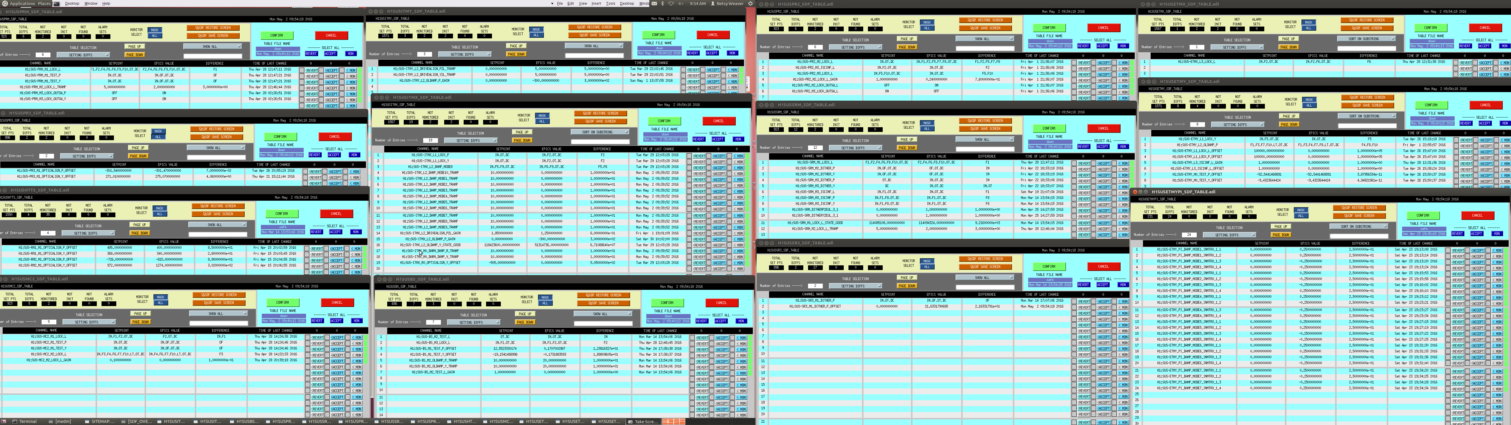
SUS: Betsy
-
ISC (& others?): Jenne
-
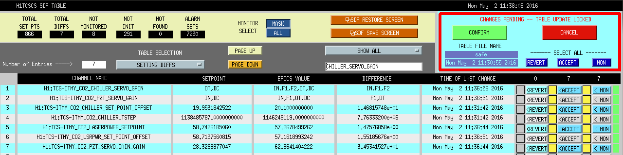
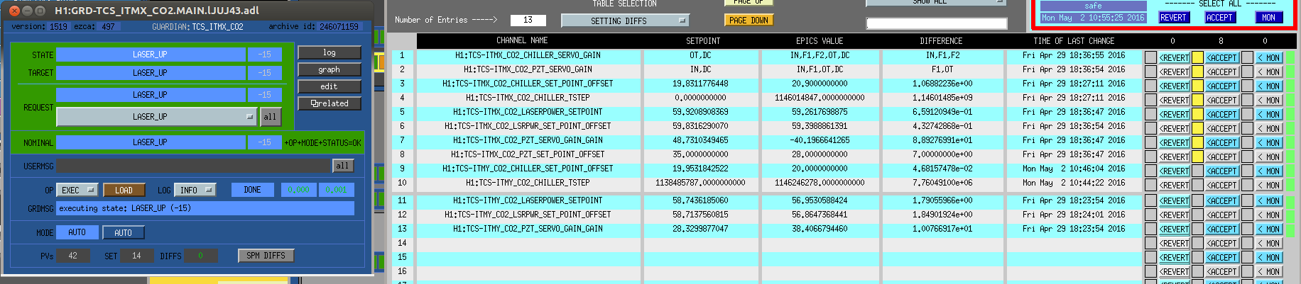
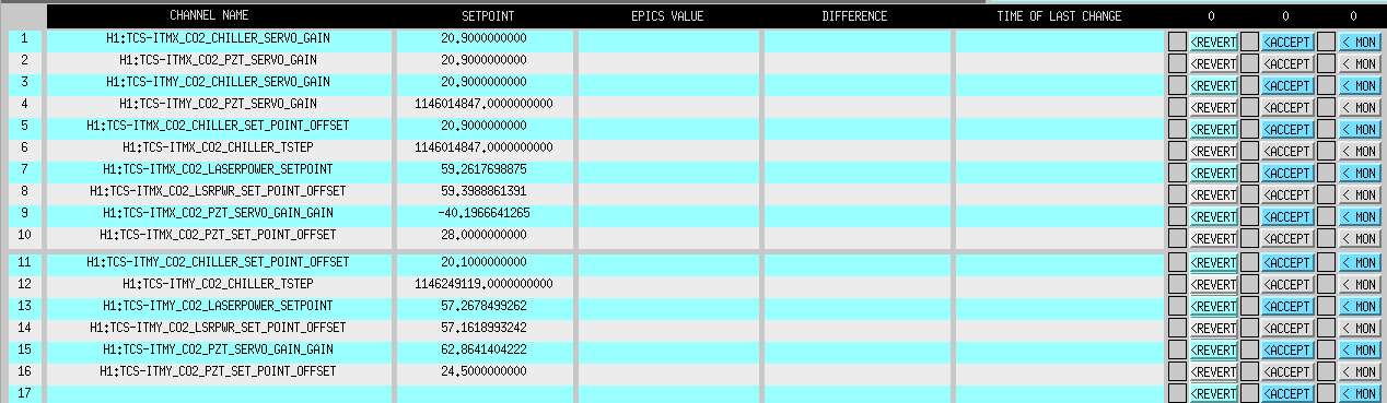
TCS: Nutsinee
-
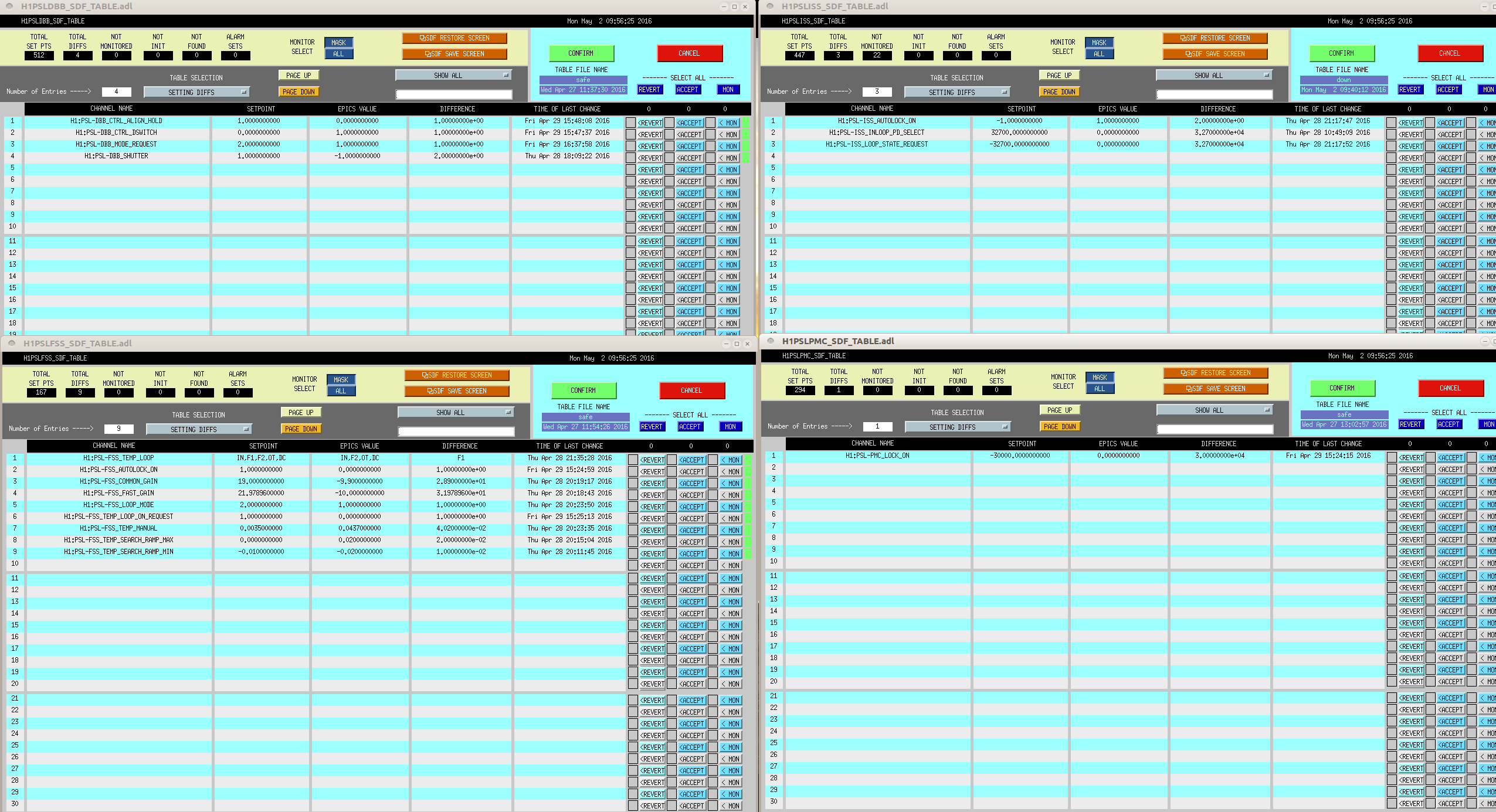
PSL, ECAT (i.e. slow controls), PEM: Corey---> rest of this entry will cover what I noted for these subsystems
It is sounding like others are ACCEPTING diffs for their subsystems so their SDFs will look green (assuming they have the safe file selected on the SDF).
I picked a few subsystems to help lighten the load for others. Since I am not an expert on these subsystems, I only took snapshot images of all the DIFFs observed on SDF. SO, these will have some RED DIFFs!
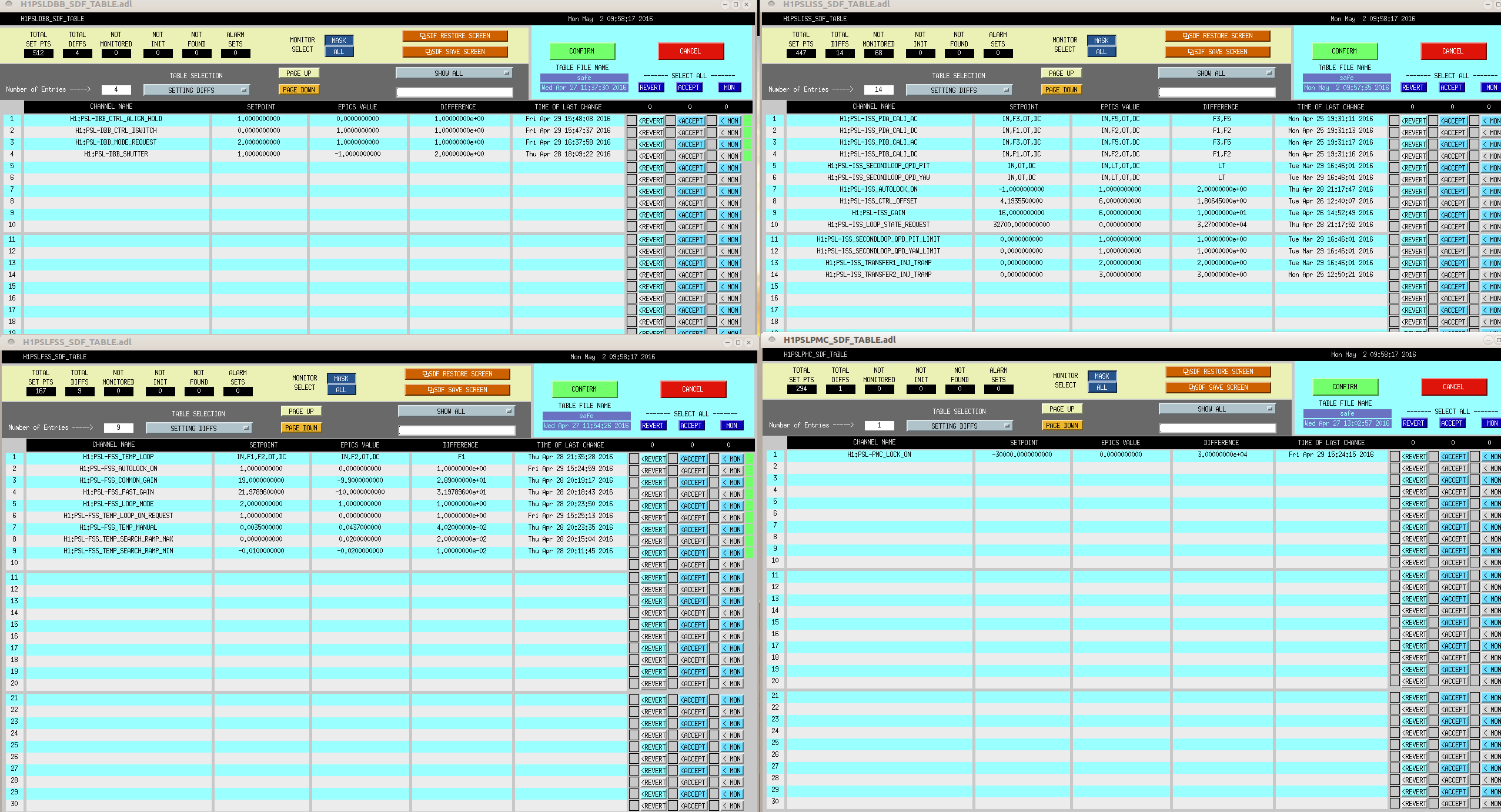
PSL SDFs came up with these files as default on the SDF Overview: DBB(safe), FSS(safe), ISS(down), PMC(safe)
ISS came up with the down file, but it also has a safe file as well (the other ones do not have down files).
Did NOT ACCEPT any DIFFS since I am not familiar with channels here. Jason/Peter are out today so did not want to ACCEPT anything without them.
Took snapshot of:
-
all files as they came up as default & also
-
with them ALL as "safes"
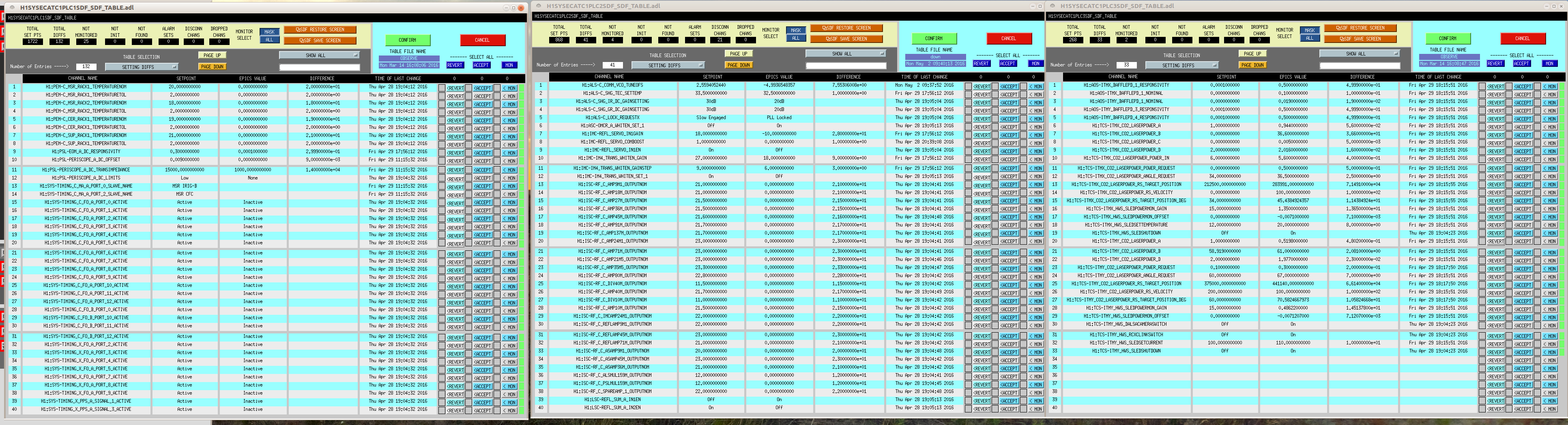
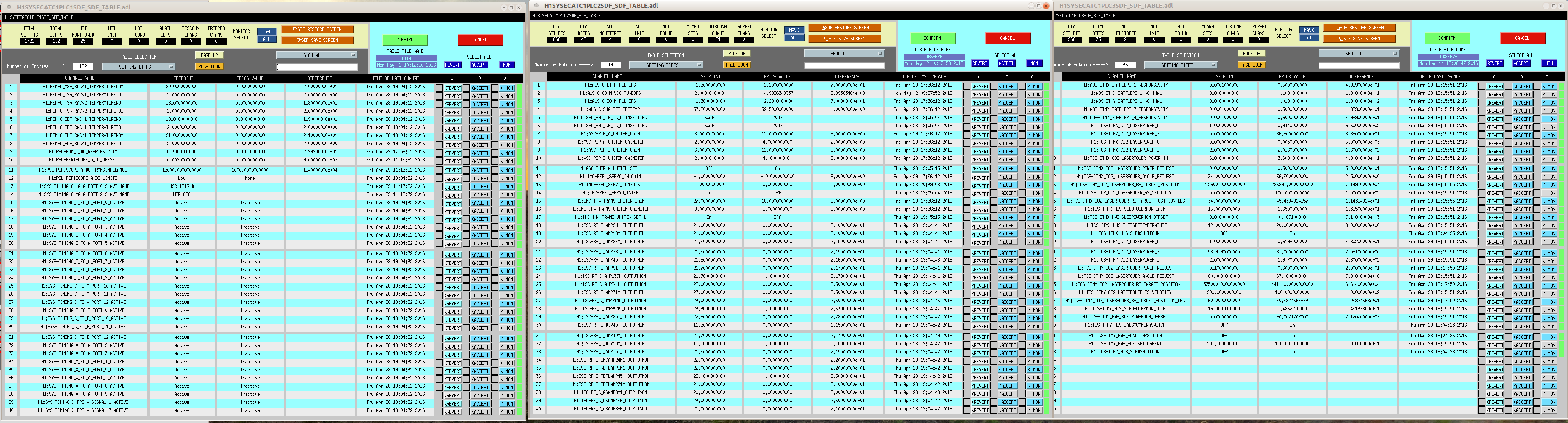
CS ECAT came up with these files as default on the SDF Overview: PLC1(OBSERVE), PLC2(down), PLC3(OBSERVE)
All had OBSERVE files, but some did/didn’t have safe & downs.
Did NOT ACCEPT any DIFFs. Daniel/Patrick said that would be OK.
Took snapshot of:
-
all files as they came up as default & also
-
with them ALL as "OBSERVEs"
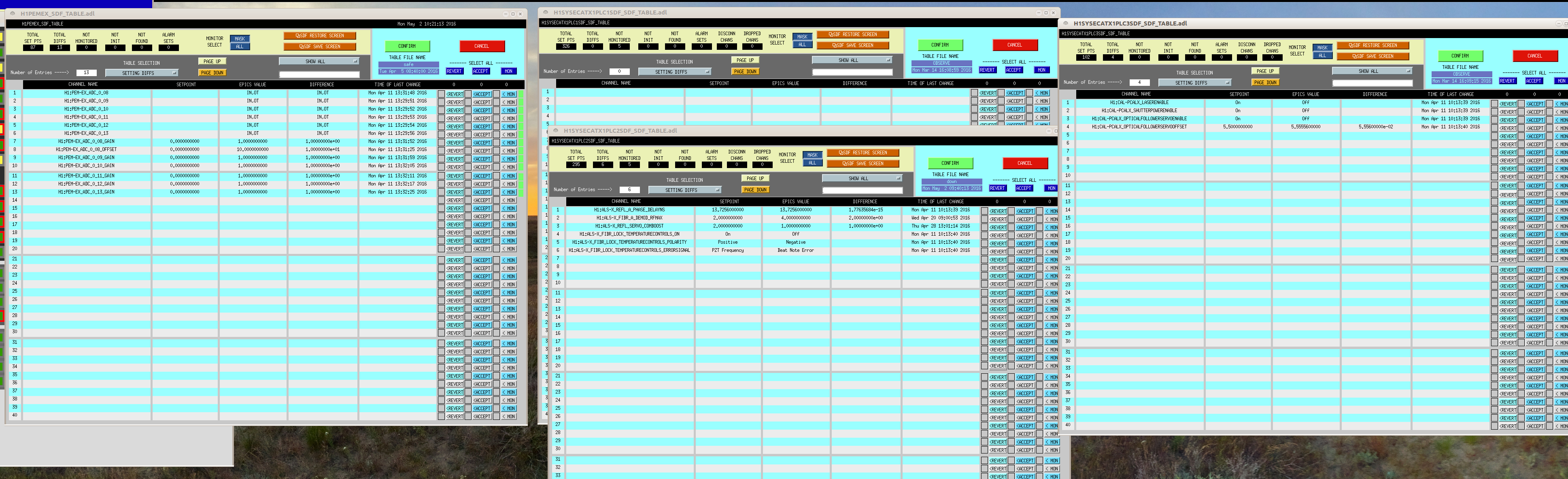
EX ECAT PLC1(observe), PLC2(down), PLC3(observe)& PEM (safe)
The ECATs mainly had OBSERVEs (plc2 had a down though).
Took snapshot of:
-
all files as they came up as default
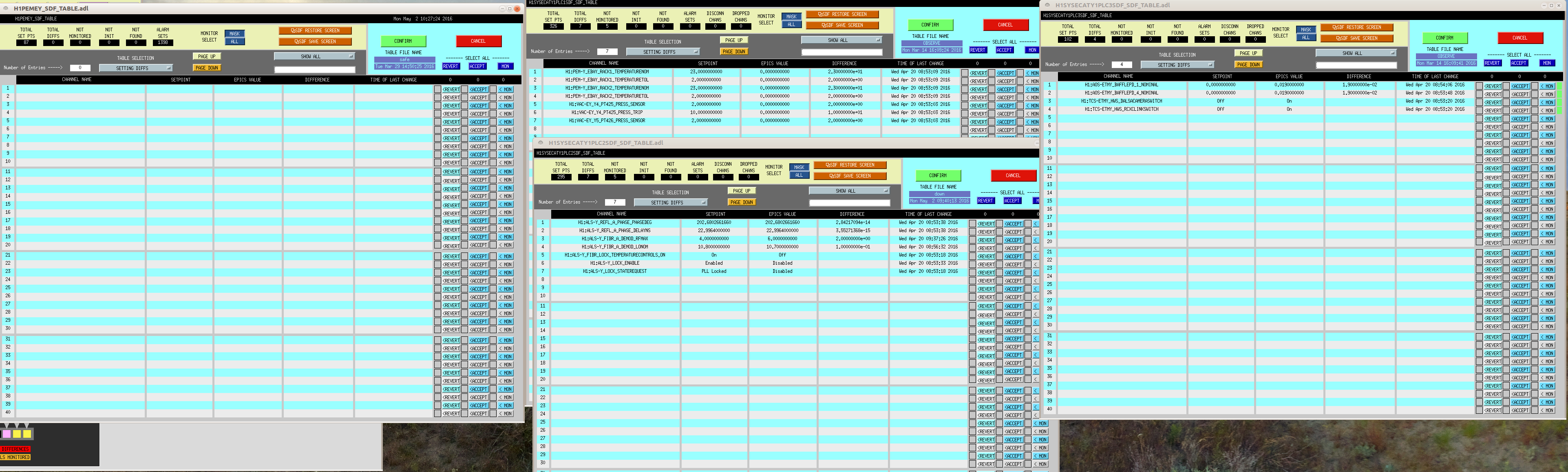
EY ECAT PLC1(observe), PLC2(down), PLC3(observe)& PEM (safe)
The ECATs mainly had OBSERVEs (plc2 had a down though).
Took snapshot of:
-
all files as they came up as default