We did a little bit of ASC work today.
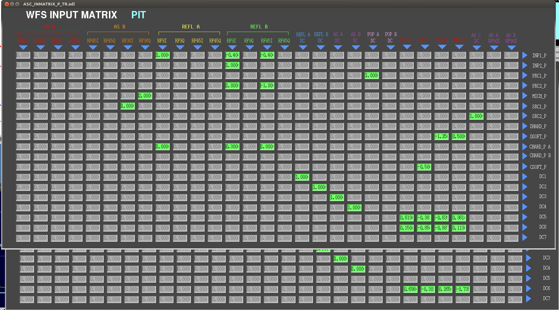
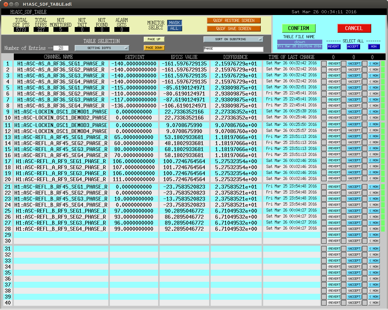
First, while Kiwamu was running a TCS test I started a script to automate phasing of the WFS. It uses the lockin, first runs a servo to set the phase of the lockin demod, then servos to minimize some signal. We have it set up right now to phase the refl WFS to minimize the PR2 pit signal in Q for both REFL 9 and 45, and to minimize the SRM pit signal in AS 36 Q. There is some code for exciting DHARD, but we need to test amplitudes, phases and gains for this. The current version of the script does its job although it is painfully slow, and is checked into the svn under asc/h1/scripts THe resulting phases are in the attached screenshot.
We saw that the instability in CHARD pit was becasue somehow the LP9 got turned on again, this is now off and CHARD seems fine.
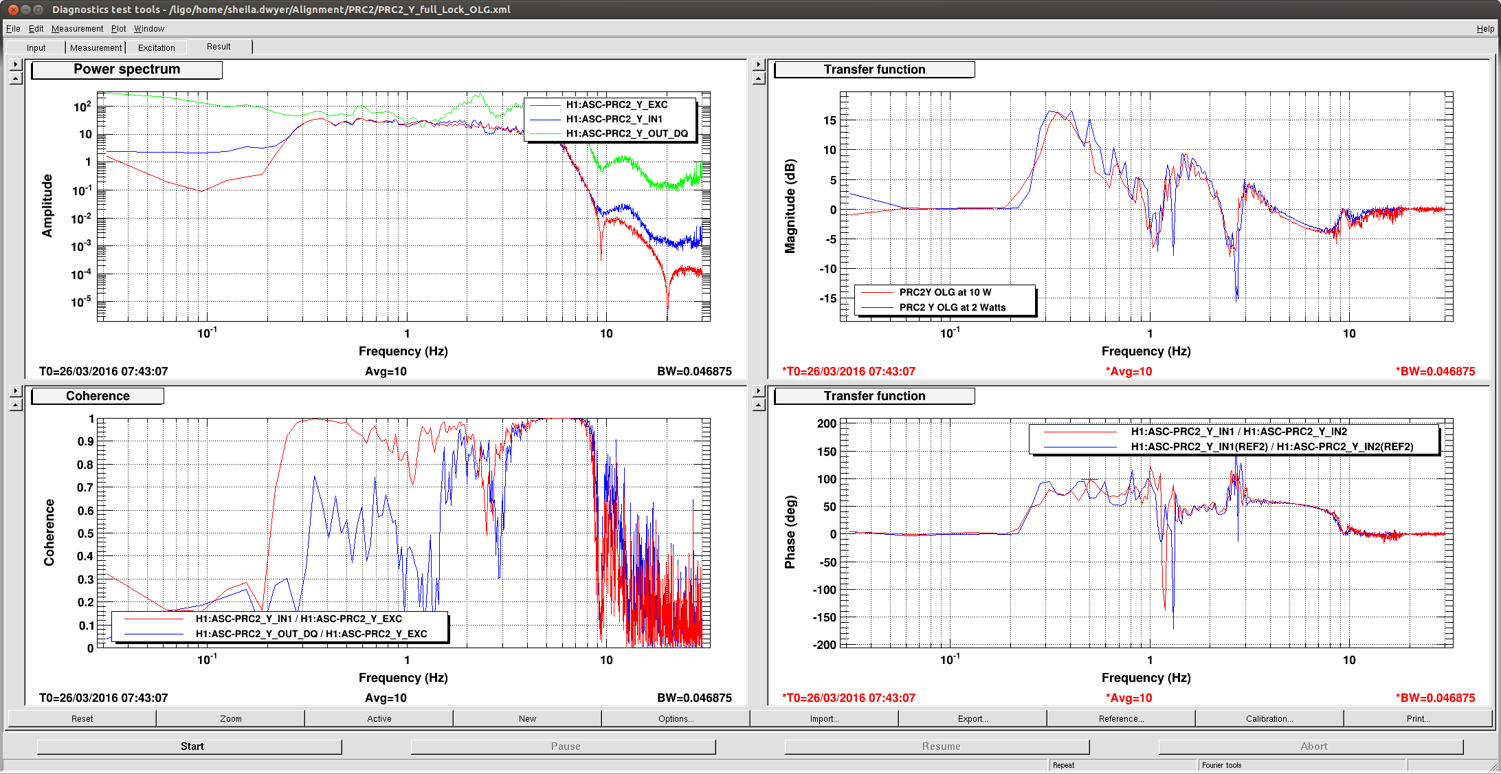
We tried powering up, were fine at 10 Watts. We had an instability in PRC1 and PRC2 yaw at 13 Watts. I reduced the Q on the complex zeros at 1.1 Hz for PRC2Y, which gives us slightly better phase and gain near the point where we seem to be unstable. Attached is a screenshot of the OLG measured with white noise at both 2 Watts and 10Watts, we might need to do a swept sign to get a good measurement around 1 Hz.
After about 10 minutes at 12 Watts, we had the usual fluctuations in the recycling gain. So the high bandwidth PRC2 loops haven't totally solved the problem.
For the record, these are angle settings that give approximately good CO2 powers tonight, and the powers to aim for from Kiwamu's note:
|
|
X power (W) |
X angle |
Y |
Y angle |
|
unlocked |
0.5 |
76 |
0.23 |
82 |
|
10W |
|
78 |
|
79 |
|
20W |
0.3 |
|
0.1 |
|
We have twice had the rotation stage for CO2 Y go to an angle that was wrong by a lot (sending a few watts to the test mass for a few seconds).
I'm leaving the IFO locked at 10Watts.