TITLE: Ops Eve Shift, 00:00-08:00UTC (16:00-23:59 PDT), all times posted in UTC"
STATE Of H1: Locked, on it's way to Low Noise, in Observe
SUPPORT: Keita and Kiwamu
SHIFT SUMMARY: Locked - something rang up - lockloss - relocking issues - back to Low Noise
INCOMING OPERATOR: Jim
ACTIVITY LOG:
- IFO locked almost exactly 4 hours
- 04:13UTC - lockloss after something rang up, visible on FOMs, did not get a chance to investigate
- relocking, X arm VCO railed at -5V, and Keita and Kiwamu identified the issue, and Kiwamu fixed
- relocking, DRIM did not lock, and then PRMI did not lock
- initial alignment
- first attempt at DRMI resulted in lockloss/down
- second attempt at DRMI was successful
- transition from DRMI lock to Low Noise went well
- 07:54UTC - IFO back in Observe

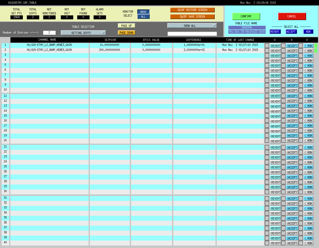
SDF changes accepted last night, with Jim's input.
ETMY_L2_DAMP_MODE3_GAIN and ETMY_L2_DAMP_MODE9_GAIN changed - screenshot attached.