Laser Status:
SysStat is good
Front End power is 31.73W (should be around 30 W)
Frontend Watch is GREEN
HPO Watch is RED
PMC:
It has been locked 19.0 days, 22.0 hr 31.0 minutes (should be days/weeks)
Reflected power is 1.681Watts and PowerSum = 25.57Watts.
FSS:
It has been locked for 0.0 days 0.0 h and 1.0 min (should be days/weeks)
TPD[V] = 1.55V (min 0.9V)
ISS:
The diffracted power is around 7.422% (should be 5-9%)
Last saturation event was 0.0 days 0.0 hours and 0.0 minutes ago (should be days/weeks)
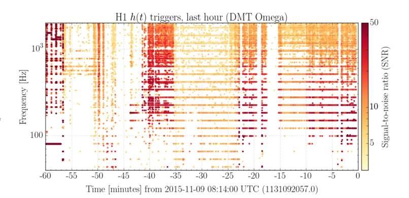
It still glitches once in a while.
I'll install a coupler and a mixer to demodulate the PSL-45MHz signal by the 45MHz distribution amplifier output and monitor it using one of the ADC channels.
Done, nothing was fixed, need to watch out for the next episode (Vern, Keita).
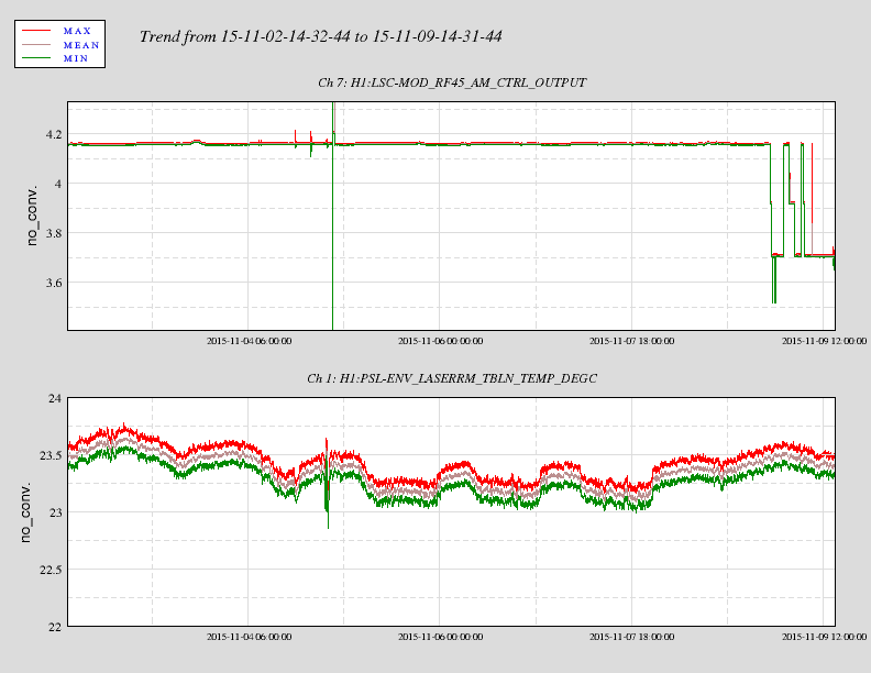
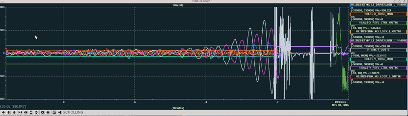
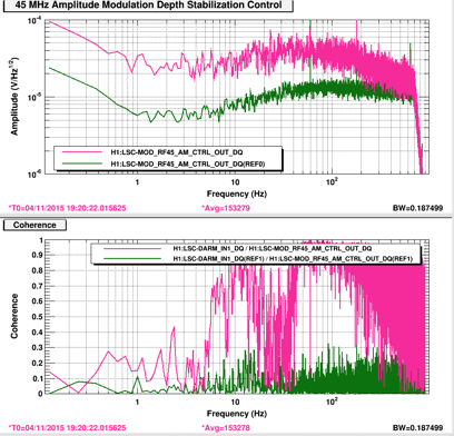
In the attached left, at the beginning after Richard and Fil swapped the cable, RF45 was still glitching. After 19:03:50 mark there was a large glitch, that's when I decided to go in, and I wrote the above alog. The hope was to see if the glitch is likely to come from the upstream or not.
Of course, right after the glitch, it stopped glitching but I didn't know as I was preparing for the incursion.
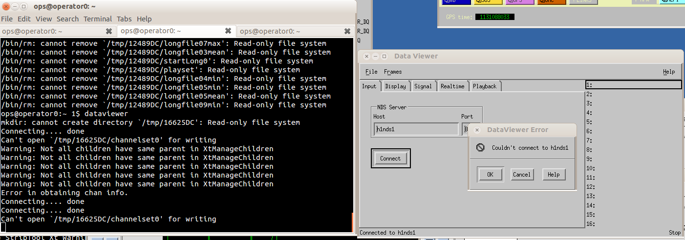
I and Vern inserted a 20dB coupler to the PSL-45MHz line on the balun on the ISC rack, demodulated it using 45MHz distribution amplifier output from the ISC rack next to it, used a 1.6MHz(?) LPF, a 50 Ohm terminator, and finally SR560 to condition the signal.
SR560 setting was DC in, output zero at 1Hz and pole at 10kHz, with the gain of 2E4 with high dynamic reserve mode. (When DC coupled, the output was 2.3V with DC gain of 200).
The output of SR560 was connected to H1:LSC-EXTRA_AI_1 channel.
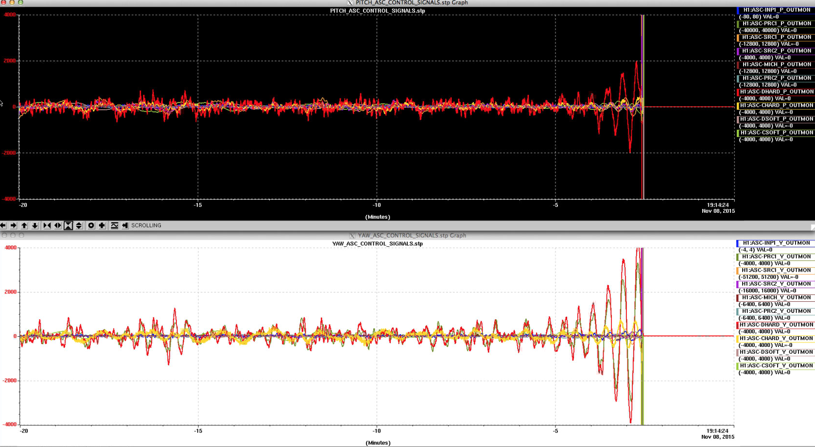
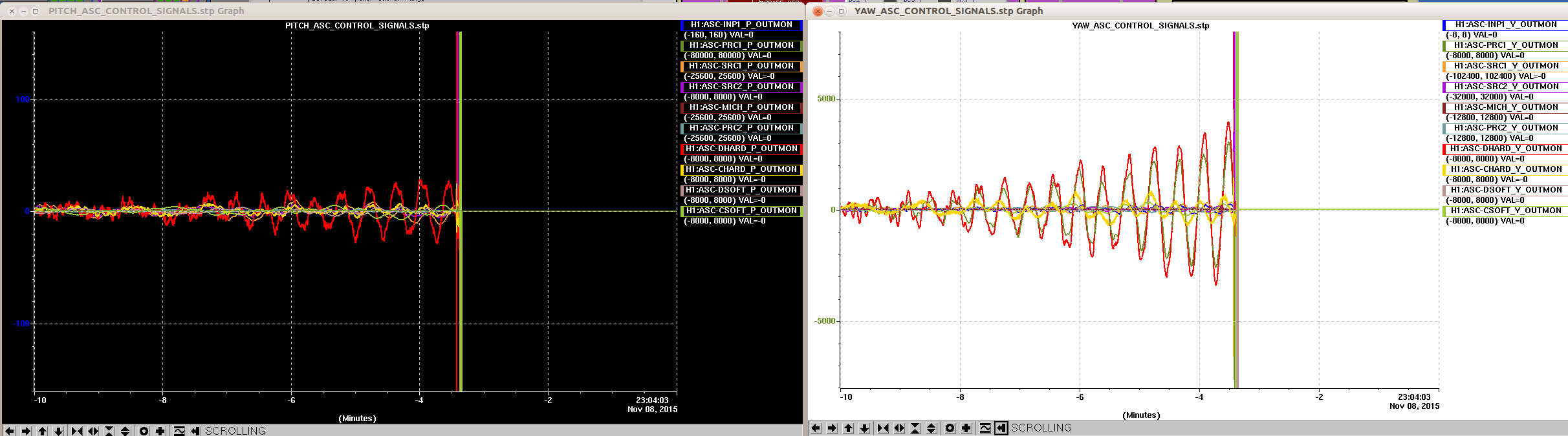
We waited for 40 minutes for a glitch but it did not happen (attached, middle and right).
Coupler was disconnected from the ISC rack, 45MHz distribution amplifier output was terminated, but the coupler/mixer/SR560 are left on the floor so it's easily put back on next time.
45MHz phase adjustment
Since RF cable was swapped (and the coil removed), I measured the RF phasing again. Using free swing MICH and measuring the TF from H1:LSC-ASAIR_A_RF45_I_ERR to Q, the phase was measured to be atan(3.45)=73.8deg.
I added a female-female and male-male N barrel in series and it was atan(4.50+-0.04)=77.5+-0.1 deg.
We are shooting for 76.4deg, and last time we adjusted it we ended up 77.3+-0.03, so I decided to go with 77.5+-0.1 deg.