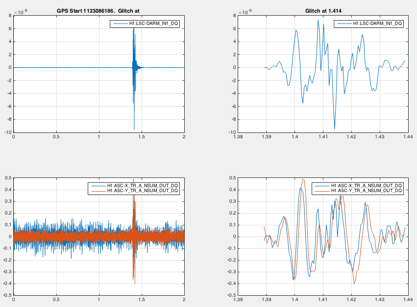
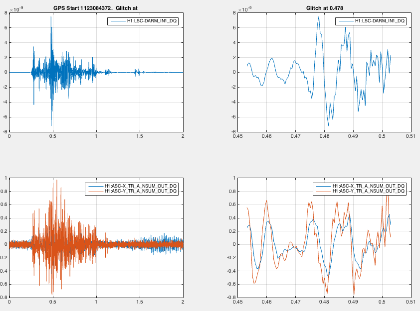
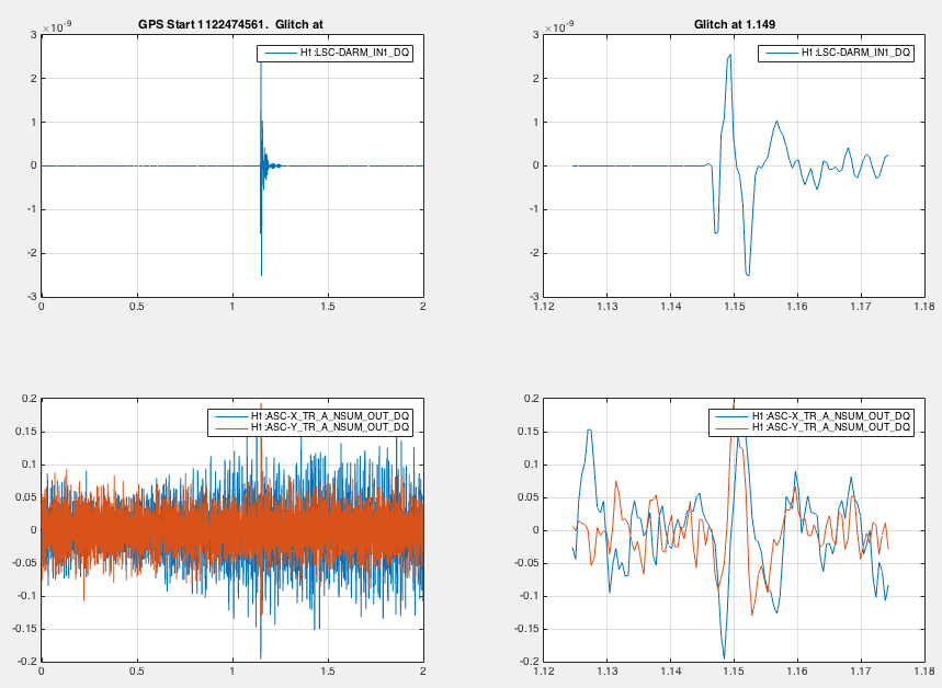
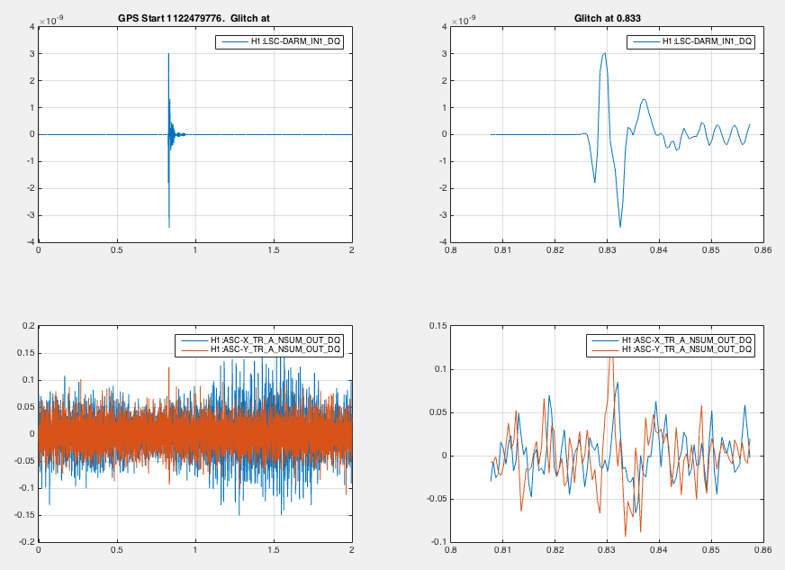
While looking at a few big glitches, I noticed that many have a curious post-glitch feature around 300Hz. The post-glitch ring seems to match the periscope frequencies we usually see noise at... could this be a hint as to the source of some of our glitches? Maybe this was fixed last night, maybe not.
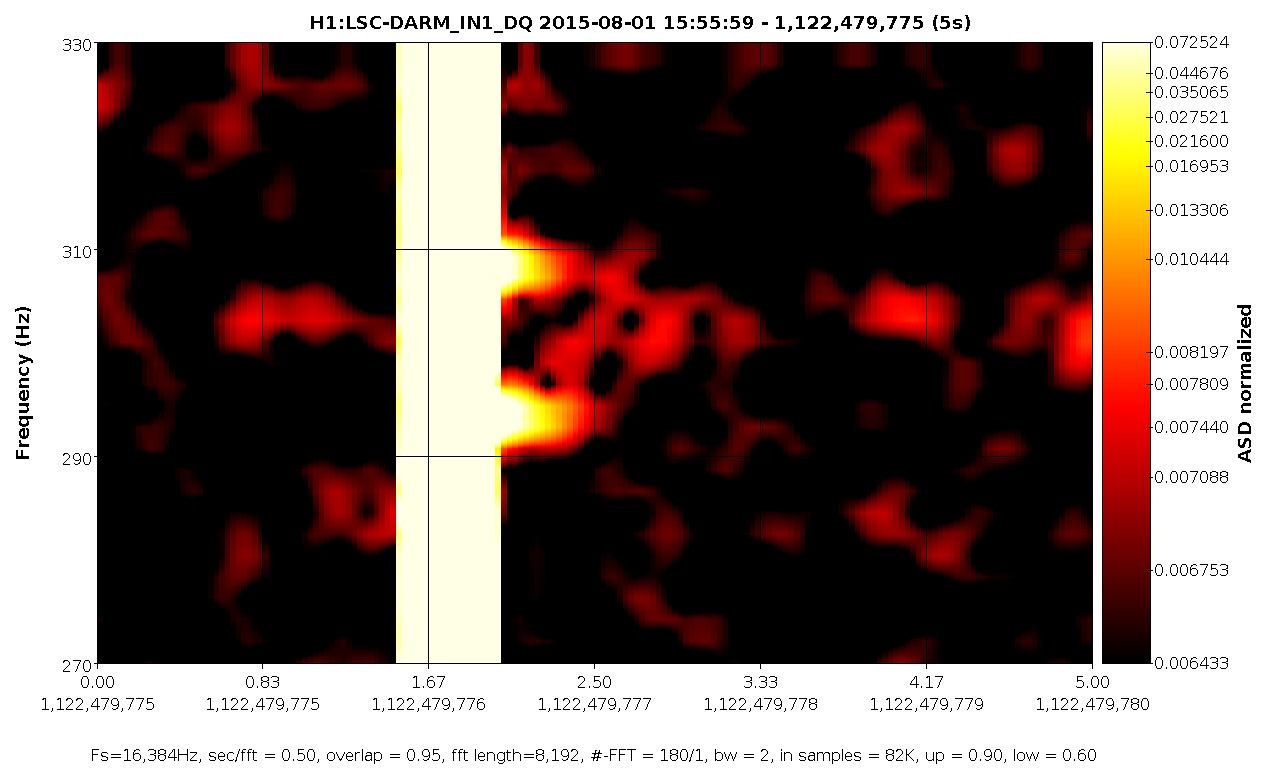
Looking at all the glitches previously indentified, it runs out that only 17 out of 151 show an excitation of the periscope peaks, as found by Matt. Here are the times:
1117617558.82
1117690781.51
1117713007.28
1117754567.25
1117873501.47
1117888336.85
1118320556.34
1118336224.73
1121762741.96
1121942076.77
1121966658.37
1121986392.35
1121991554.23
1122466633.18
1122474562.14
1122479776.82
1122484101.65