jeffrey.kissel@LIGO.ORG - posted 20:48, Tuesday 21 July 2015 (19813)
7/21 Maintenance Day / Relocking Team Debriefing
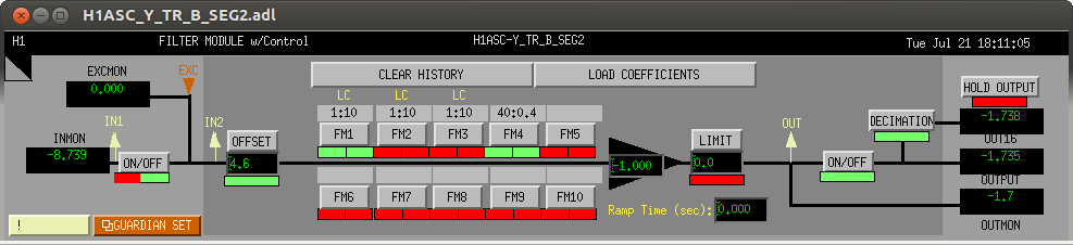
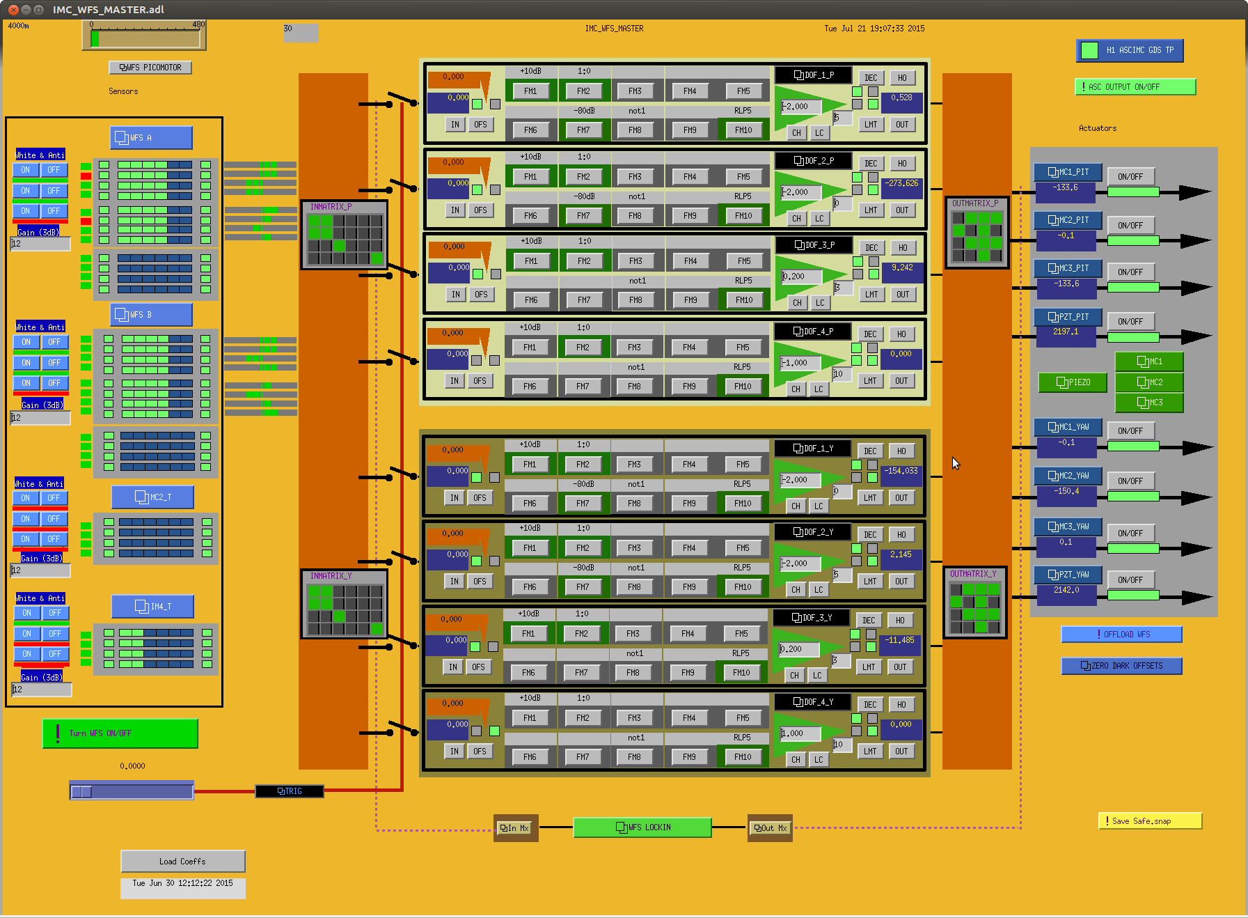
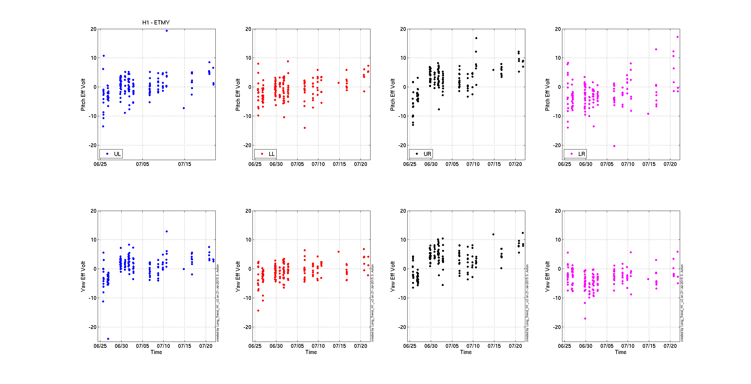
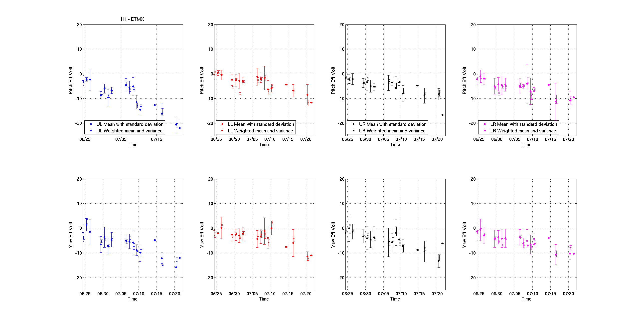
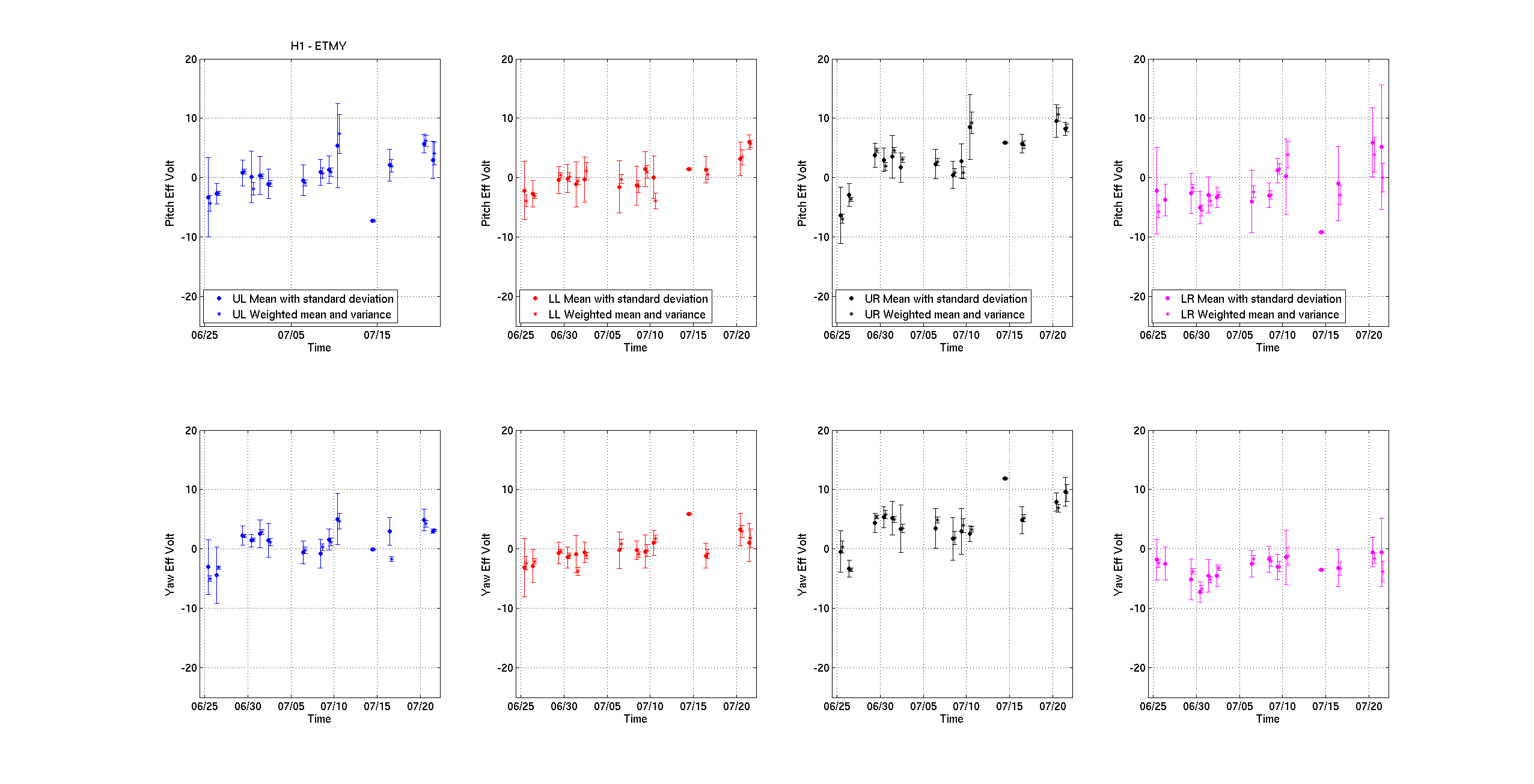
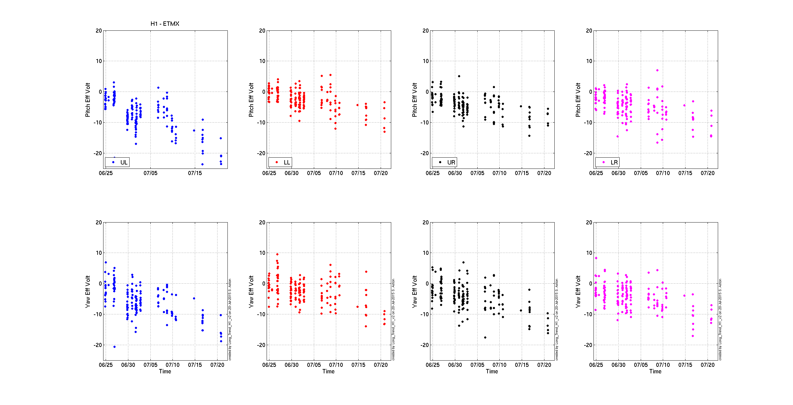
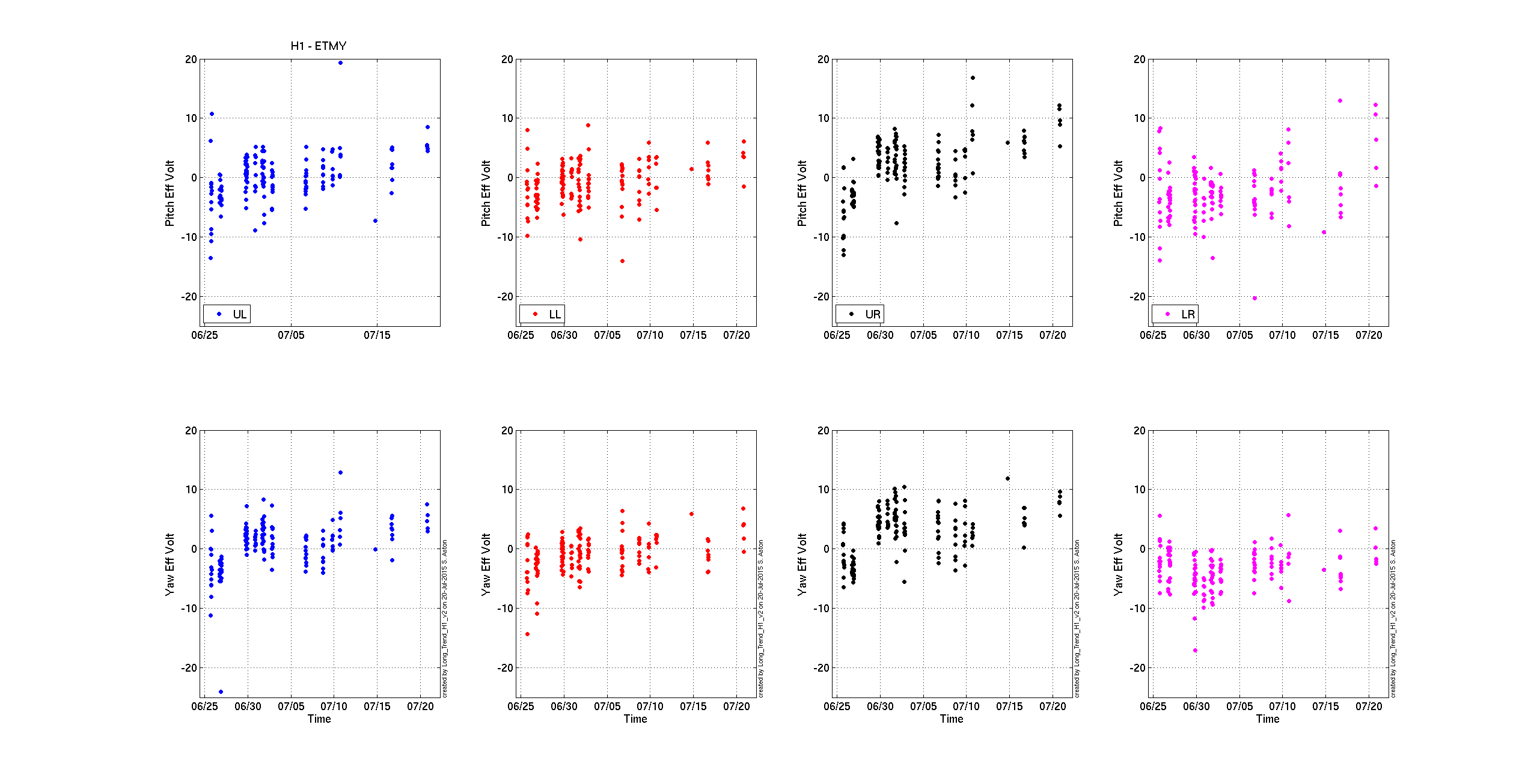
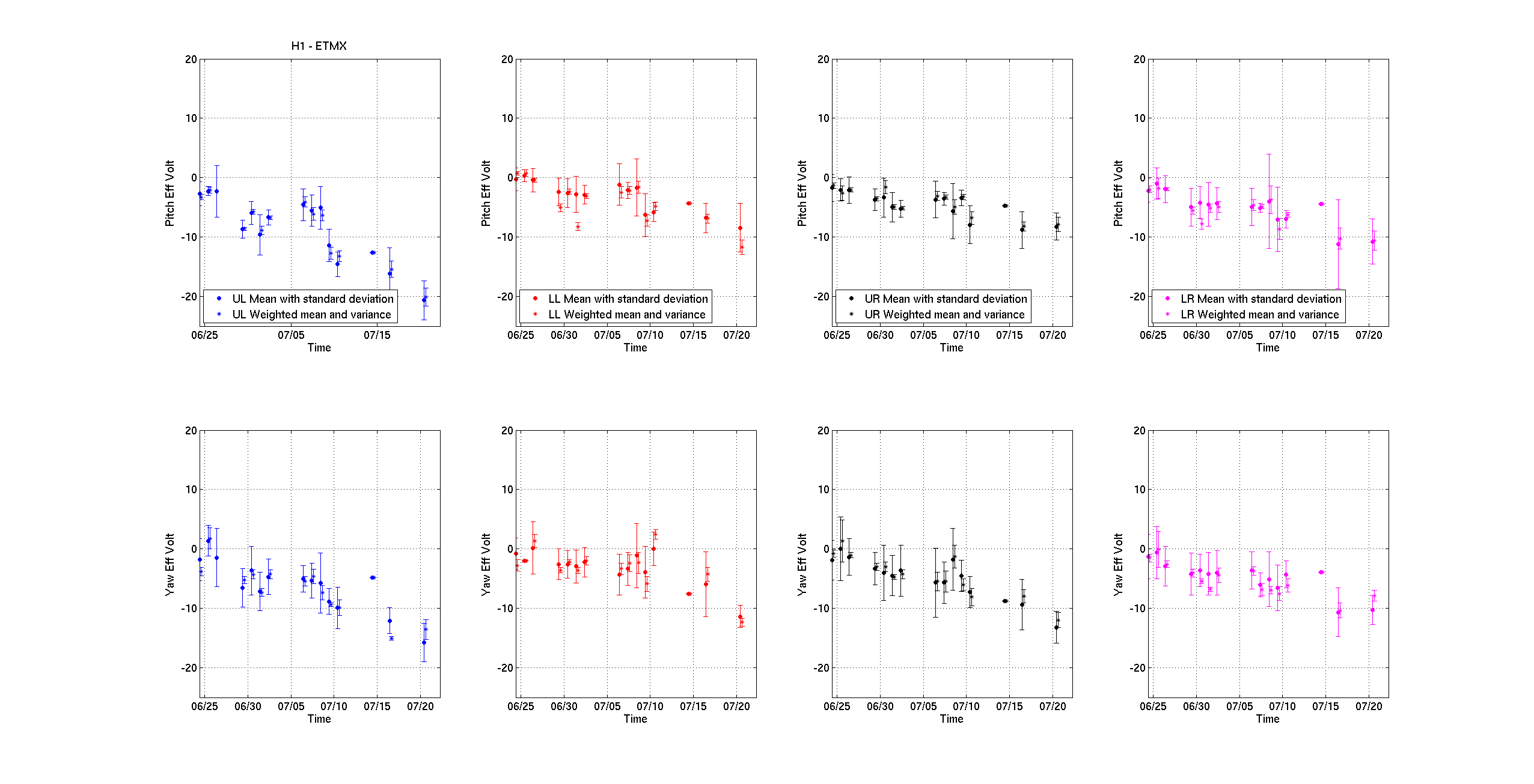
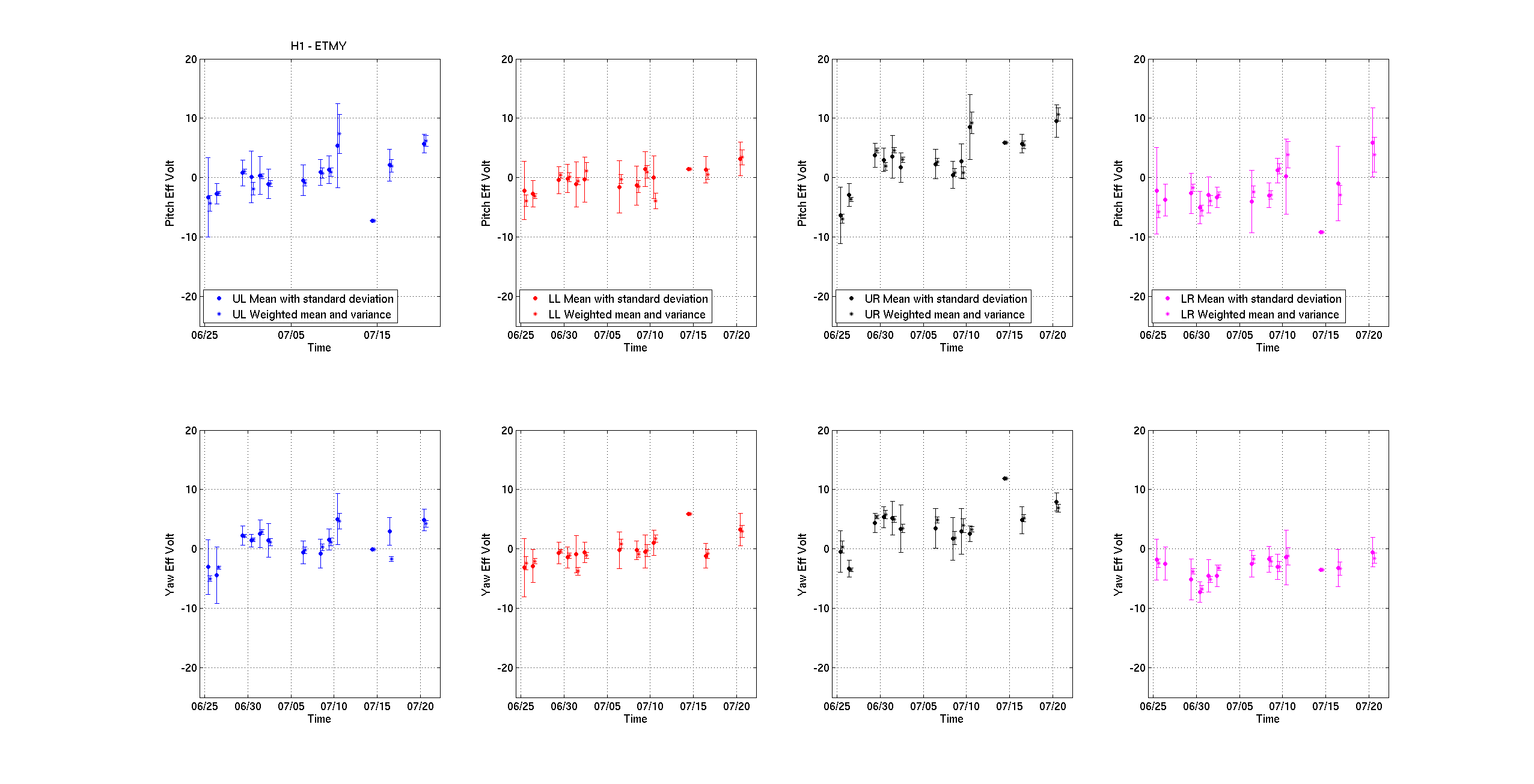
J. Kissel, B. Weaver, N. Kijbunchoo, T. Sadecki, E. Hall, S. Dwyer

Another heavily loaded Tuesday today. For what we planned to do, see LHO aLOG 19770. We have managed to complete the IFO recovery, on the same day, and before the sun has gone down!! Most of the failures and deviations from plan today were software problems, which didn't fix the problem they'd intended to fix, were slow to recovery, or had to be reverted because of new found bugs. Towards the tail end of recovery, there were other problems that were more related to half-finished or mistakes from commissioning last night, but thankfully by the time we had reached recovery the guilty commissioned had arrived on site and confessed their sins. In summary -- not so bad -- but there was little IFO systems' software actually restarted.


(All times PDT)
07:00 Richard brings SEI platforms and SUS to SAFE/OFFLINE LHO aLOG 19778

07:30 Richard, Daniel and Fil swap the internal GPS of the timing master for the external GPS unit. LHO aLOG 19782
      This did *not* crash any front-ends, so the corner station models have stayed up all day, and were otherwise unaffected by the rest of maintenance. This was a huge relief.

08:00 Richard and Fil continue moving GPS Antennae on roof, no further impact on the timing system
     Hugh and Jim W begin ramping down HEPI for pump maintenance
     Jim B heads down to EY to begin timing fanout replacement and SUS fast front-end BIOS upgrade

09:15 Begin corner station SEI / SUS and IMC recovery
     A little bit of trouble bringing the IMC up because the WFS output had not been offloaded in a while, so with the initial alignment the WFS trigger PD had a little bit too low of light. We've since offloaded the IMC WFS DC values to the alignment sliders to alleviate this, LHO aLOG 19814
     HEPI HAM2 trips during recovery, HAM5 has he usual problems with Rogue Excitation vs. Watchdog RESET, but otherwise a smooth restart of the remaining SEI and SUS.
     Vinny starts PEM sensor calibrations.

09:30 IMC recovery complete
      Jim's finished with EY Timing fanout and SUS fast FE, find that the BIOS upgrade makes no difference to ADC Timing Errors, but moves on to EX.
      Cable runs for PEM cosmic ray detector begin. LHO aLOG 19804

10:00 Betsy and Jeff begin EY SUS ETMY's RCG upgrade to get all improvements to TrueRMS and SDF sort-on-substring, discover that branch 2.9 (which has all improvements to TrueRMS) has some terrible BURT/SDF restore bug. End result is to compile against RCG 2.9.5 LHO aLOG 19793
      Hugh and Jim finish repair of HEPI pump station, and it's brought back in loop. LHO aLOG 19794

10:15 TCSX Laser trips from PEM cable pulling, recovered shortly after by Nutisnee. Ha! We knew to expect this one! LHO aLOG 19786

10:30 Huh discovers EY HEPI fluid level is significantly lower than last week, suspects accumulator bladder has let in fluid. Executive decision is to wait until next week to assess and repair. LHO aLOG 19796.
      EY HEPI Trips
      Fil and Andres head to EX to being LVLN ESD driver install and cable pulling. The new ETMX ESD LVLN Driver was literally, merely installed in the rack, but has not been hooked up. LHO aLOG 19803

11:00 Discover that EY SUS has IOP DAC output issues after finished of recompilation against RCG 2.9.5, requires full front-end shut down and restart (including TMSX and new EXPI model) LHO aLOG 19793
      Jim B. is done with BIOS upgrade for EX SUS fast-front end. Also no improvement in timing errors.

11:15 EY front-end model recovery complete
      EY SEI / SUS restoration begins
      SEI system up and running, SUS restared to damping and aligned, charge measurements begun to assess health.

11:20 EX front end model restoration begins, encountering the same problems with no IOP DAC outputs. Restart entire front-end, like EY.
      Begin EX SEI / SUS restoration begins
      Charge measurements on ETMY ESD complete, confirm charge is OK and little no change in charge since yesterday LHO aLOG 19764
      EY recovery complete.

11:40 ISC EX and ISC EY front-end epics settings restored to 05:00
      SUSAUX model updates installed, having been compiled against RCG 2.9.5 LHO aLOG 19780
      Preventative maintenance reboots begin
            Conlog computer restarted, no problems LHO aLOG 19789

12:00 MX / MY PEM model changes installed LHO aLOG 19809

12:10 DAQ / Frame Builder restart, doesn't come back gracefully, needs a lot of prodding from Jim and Dave.

12:20 Frontend network switch restarted, does not fix EPICs slowdown issue
      EPICs Gateway restarted, does not fix EPICs slowdown issue
      Hardware injection machines turned OFF, does not fix EPICs slowdown issue

12:45 Guardian machine restarted. Doesn't come back up on first try, does better the second time LHO aLOG 19812
      Attempt to begin ETMX charge measurements to confirm health, but EX Beckhoff PLCs crash, not necessarily unexpectedly. After restoration, settings are restored to 05:00
      Beckhoff crash trips ETMX ESD HV Driver power supplies, and renders Beckhoff remote restart useless.

13:00 Fil drives to end station to turn ESD power supplies back ON.

13:15 Charge measurements on ETMX ESD begin, only one data point, but confirms EX ESD is functional
      EY recovery complete
      Begin Full IFO Recovery

13:45 Initial alignment complete for green and PRM. recovery up to this point was MUCH more smooth this week

14:00 Discover that certain visiting commissioners have removed vital MICH and SRCL lock acquisition filters last night. Filters restored from archive, and we move on.

14:20 Initial alignment complete for IFO
      Begin lock acquisition sequence

14:50 Reach DC Readout, increase to high power, but lose lock instantly upon transition from ETMX to ETMY as DARM actuator

      An ETMY ISI trip, later associated with IPC communication problems because of ADC timing issues from SUS front-end. LHO aLOG 19808, LHO aLOG 19799
      several more lock-losses, a few on transition to TR CARM, a few more on transition to ETMY

16:45 Discover that certain visiting commissioners have left the ETMY hierarchical control filters in a half-commissioned state last night. Filters restored from archive.

17:00 Frame builder crashes again. LHO aLOG 19811.
      Evan notices that Trans QPD dark noise for X arm is huge. While the IFO continues to lose lock on TR CARM transition, Evan and Shiela investigate what possible QPD offset settings might have been lost.

18:00 Shiela just gives up, assumes that the dark noise of the QPDs has actually changed (perhaps because of ETMX electronics work earlier in the day)

19:40 Full IFO recovered to a stable 60 [Mpc]!