J. Kissel, for the Calibration Team
Summary:
As the calibration group begins to post representative, "best" sensitivities for engineering and observing runs, we must narrow down a process for deciding what is the "best" time. As such, I outline the process by which I've chosen the "best" ASD for ER7, which is formed from a 600 [sec] stretch of data starting at Jun 09 2015 14:41:44 UTC. This resulting H1 ER7 sensitivity plot (and associated ASCII dump of it), and all future official IFO sensitivity plots, will be linked from the top-level tree for sensitivity plots, found in G1500623.
-----------
First, a not-so-brief recap of ER7 (and the weeks leading up to it), with calibration group goggles:
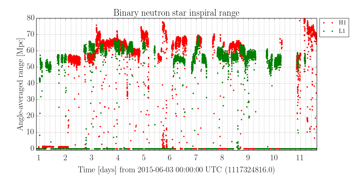
For assistance, I show the sensemon inspiral range, as computed using the GDS-CALIB_STRAIN channel taken from DetChar's ER7 Summary Page, reattached here for convenience. Also from a different tab on the same page (the Segments Tab), where I get the ER7 H1:DMT-ANALYSIS_READY segment list shown below.
- 2015-Apr to 2015-May
Several DARM Open Loop Gain TFs are taken to estalished that the DARM Coupled Cavity Pole is stationary at 350 pm 10 [Hz] (LHO aLOGs 18186)
- 2015-May-15
OMC Readout Gain Scaling between RF DARM and OMC Readout commissioned to allow for changes to IFO Power and DARM Offset while on DC readout (LHO aLOG 18470)
- 2015-May-21
We finish installation of ESD low-noise, low-voltage driver (LHO aLOGs 18568 and 18579).
- 2015-May-22
Suspiciously find that we have to flip the sign of digital requested ESD BIAS voltage to get the IFO to transition from EX to the new EY driver.
- 2015-May-26 to 2015-May-29
- All measurements used to inform the actuation strength are taken (LHO aLOGs 18767, 18718, 18711, 18758)
- All measurements used to set the sensing function's overall gain and informed the DARM loop frequency dependent uncertainty are taken (LHO aLOG 18769)
- 2015-Jun-02
- Gain matching between RF DARM and OMC Readout more robust, such that OMC Readout 18768
- Frequency domain model is finished (settling on 355 [Hz] for the cavity pole frequency, though we hadn't gotten a good measure of it due to flaws in the DARM OLG TF model) and handed off to time-domain calibrators to convert to FIR filters (LHO aLOG 18769)
- 2015-Jun-03
The night before / morning of ER7 Maddie restarts the GDS calibration code with newly updated filters from DARM Model (LHO aLOG 18813)
- ER7 Starts, and we transfer the timeline to annotating the segment list:
Segment GPS Start GPS End Duration UTC Start PDT Start Notes
Number [sec]
[ 0] [1117408143] [1117408494] [ 351] 'Jun 03 2015 23:08:47 UTC' 'Jun 03 2015 16:08:47 PDT' % ^ Double-counting of AA and AI filters in GDS-CALIB_Strain
[ 1] [1117421174] [1117424706] [ 3532] 'Jun 04 2015 02:45:58 UTC' 'Jun 03 2015 19:45:58 PDT' % | filters (18813 and 19219)
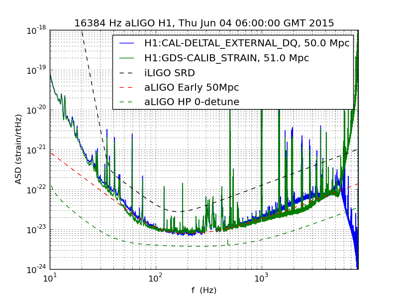
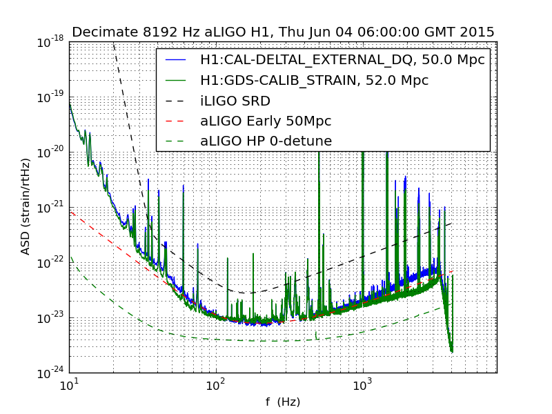
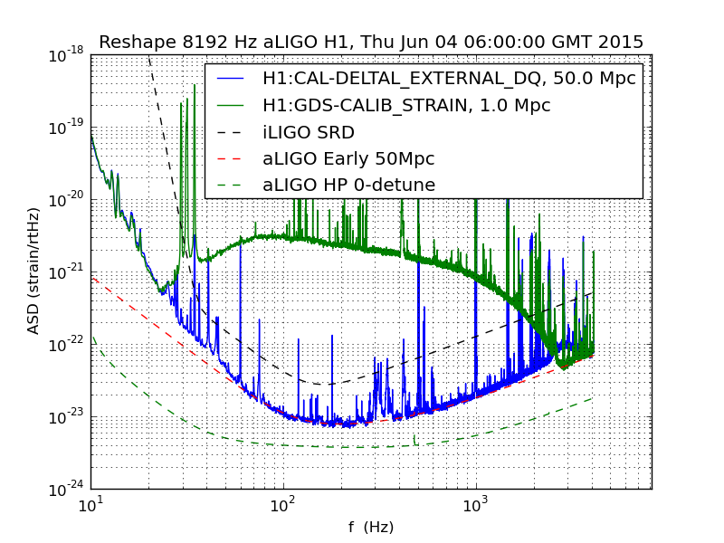
[ 2] [1117426833] [1117433922] [ 7089] 'Jun 04 2015 04:20:17 UTC' 'Jun 03 2015 21:20:17 PDT' % | exposed a bug in decimation of channel for SenseMon
[ 3] [1117433927] [1117449201] [15274] 'Jun 04 2015 06:18:31 UTC' 'Jun 03 2015 23:18:31 PDT' % | calculation (see attachments 2, 3, and 4)
[ 4] [1117450992] [1117457269] [ 6277] 'Jun 04 2015 11:02:56 UTC' 'Jun 04 2015 04:02:56 PDT' % |
[ 5] [1117480924] [1117490420] [ 9496] 'Jun 04 2015 19:21:48 UTC' 'Jun 04 2015 12:21:48 PDT' % |
[ 6] [1117493328] [1117499527] [ 6199] 'Jun 04 2015 22:48:32 UTC' 'Jun 04 2015 15:48:32 PDT' % V GDS filters are fixed after this segment
[ 7] [1117507669] [1117545165] [37496] 'Jun 05 2015 02:47:33 UTC' 'Jun 04 2015 19:47:33 PDT' % ---
[ 8] [1117561284] [1117562229] [ 945] 'Jun 05 2015 17:41:08 UTC' 'Jun 05 2015 10:41:08 PDT' % | Viable Calibration of GDS-CALIB_STRAIN
[ 9] [1117570100] [1117592884] [22784] 'Jun 05 2015 20:08:04 UTC' 'Jun 05 2015 13:08:04 PDT' % ---
[10] [1117601338] [1117665437] [64099] 'Jun 06 2015 04:48:42 UTC' 'Jun 05 2015 21:48:42 PDT' % --- IFO Configuration Changes!
[11] [1117667359] [1117702258] [34899] 'Jun 06 2015 23:09:03 UTC' 'Jun 06 2015 16:09:03 PDT' % | Lots of things:
[12] [1117709888] [1117743019] [33131] 'Jun 07 2015 10:57:52 UTC' 'Jun 07 2015 03:57:52 PDT' % | - IFO Input Power to 23 [W] :: Cause for Calibration Uncertainty (LHO aLOGs 18923 and 19031)
[13] [1117748054] [1117773188] [25134] 'Jun 07 2015 21:33:58 UTC' 'Jun 07 2015 14:33:58 PDT' % | - ASC tuned for higher power (LHO aLOG 18923)
[14] [1117803358] [1117814235] [10877] 'Jun 08 2015 12:55:42 UTC' 'Jun 08 2015 05:55:42 PDT' % | - ~300 [Hz] performance improved by changing IMC DC Alignment (LHO aLOGs 18877, 18894, 18929)
[15] [1117814313] [1117815464] [ 1151] 'Jun 08 2015 15:58:17 UTC' 'Jun 08 2015 08:58:17 PDT' % | - MICH FF is retuned (LHO aLOG 18878)
[16] [1117829201] [1117833161] [ 3960] 'Jun 08 2015 20:06:25 UTC' 'Jun 08 2015 13:06:25 PDT' % ---
[17] [1117853451] [1117854502] [ 1051] 'Jun 09 2015 02:50:35 UTC' 'Jun 08 2015 19:50:35 PDT' % --- % Lock stretched polluted by Beam Tube Cleaning Glitches
[18] [1117861010] [1117866838] [ 5828] 'Jun 09 2015 04:56:34 UTC' 'Jun 08 2015 21:56:34 PDT' % |
[19] [1117868188] [1117878119] [ 9931] 'Jun 09 2015 06:56:12 UTC' 'Jun 08 2015 23:56:12 PDT' % |
[20] [1117884319] [1117890432] [ 6113] 'Jun 09 2015 11:25:03 UTC' 'Jun 09 2015 04:25:03 PDT' % | Power restored to 17 [W] (though all above noise tunings remain, so sensitivity is better)
[21] [1117890837] [1117891071] [ 234] 'Jun 09 2015 13:13:41 UTC' 'Jun 09 2015 06:13:41 PDT' % | Calibration Validity Returns
[22] [1117891490] [1117897783] [ 6293] 'Jun 09 2015 13:24:34 UTC' 'Jun 09 2015 06:24:34 PDT' % | %%% <<< 600 [sec] OF THIS SEGMENT IS USED FOR "BEST" ER7 ASD %%%
[23] [1117930374] [1117936993] [ 6619] 'Jun 10 2015 00:12:38 UTC' 'Jun 09 2015 17:12:38 PDT' % |
[24] [1117937002] [1117940975] [ 3973] 'Jun 10 2015 02:03:06 UTC' 'Jun 09 2015 19:03:06 PDT' % |
[25] [1117941598] [1117946873] [ 5275] 'Jun 10 2015 03:19:42 UTC' 'Jun 09 2015 20:19:42 PDT' % |
[26] [1117984389] [1117987778] [ 3389] 'Jun 10 2015 15:12:53 UTC' 'Jun 10 2015 08:12:53 PDT' % |
[27] [1118009073] [1118009809] [ 736] 'Jun 10 2015 22:04:17 UTC' 'Jun 10 2015 15:04:17 PDT' % |
[28] [1118019595] [1118022123] [ 2528] 'Jun 11 2015 00:59:39 UTC' 'Jun 10 2015 17:59:39 PDT' % |
[29] [1118038511] [1118088249] [49738] 'Jun 11 2015 06:14:55 UTC' 'Jun 10 2015 23:14:55 PDT' % --- END OF FOCUS DATA TAKING during this lock stretch, at 1118070016 (LHO aLOG 19085)
% --- ESD Driver is RESET for charge testing, (LHO aLOG 19095)
% | This inadvertently changes bias voltage and actuation strength (LHO aLOG 19110)
% --- Reset driver's digital bias properly compensated before this lock stretch
[30] [1118207683] [1118207892] [ 209] 'Jun 13 2015 05:14:27 UTC' 'Jun 12 2015 22:14:27 PDT' % ---
[31] [1118212512] [1118213354] [ 842] 'Jun 13 2015 06:34:56 UTC' 'Jun 12 2015 23:34:56 PDT' % | Remaining locks have wrong and uncertain actuation strength
[32] [1118268553] [1118269137] [ 584] 'Jun 13 2015 22:08:57 UTC' 'Jun 13 2015 15:08:57 PDT' % | between reality and GDS-CALIB_STRAIN
[33] [1118303427] [1118329216] [25789] 'Jun 14 2015 07:50:11 UTC' 'Jun 14 2015 00:50:11 PDT' % ---
----------------
Now that I've established which lock stretches I can use that are calibrated to within the stated uncertainty of 50% in amplitude and 20 [deg] in phase (as stated in LHO aLOG 18769), which are segments
viableSegments = [7:9 17:29];
I began to search for the best lock stretch. To do so, I plotted a time series of the sensemon BNS inspiral range produced from H1:GDS-CALIB_STRAIN, i.e. 'H1:DMT-SNSH_EFFECTIVE_RANGE_MPC.mean,m-trend' (SNSW is calculated from CAL-CS, which we know is in-accurate; see G1500750), and can immediately found that the sensitivity of the latter segments were better (again, because of Robert's tuning of the IMC alignment to reduce the coupling of angular jitter on the beam from the PSL, which happened during the 23 [W] segments LHO aLOG 18929),
viableSegments_wGoodRange = [17:29];
This plot is shown in the first page of the attached .pdf, and was generated by the script,
/ligo/svncommon/CalSVN/aligocalibration/trunk/Runs/ER7/H1/Scripts/segments_ER7.m
Looking for the longest lock stretch with most consistently high range, I chose the 22nd segment, starting at 1117891490, 'Jun 09 2015 13:24:34 UTC', 'Jun 09 2015 06:24:34 PDT'. Once I had this lock stretch, I used
/ligo/svncommon/CalSVN/aligocalibration/trunk/Runs/ER7/H1/Scripts/produceofficialstrainasds.m
which narrows down the lock stretch into a "best" 600 seconds, where the length of the time-series, 600 [sec], is chosen because I desired a binwidth of 0.185 [Hz] and many-many averages (it works out to be 111 averages, using asd2.m), so the end-resulting ASD is nice and clean looking.
Here's how I narrowed down which 600 [sec] of the 6293 [sec] long lock stretch (follow along with pg 2 of the .pdf attachment):
- Zoom in on the SNSH-calculated, inspiral range time series over the entire lock stretch. (shown in blue)
- Take the median of the SNSH-calculated, inspiral range time series over the entire lock stretch. The median for this lock stretch is 66.8 [Mpc] (shown as the green dotted line). I chose the median (instead of the mean) so as to not be influenced by the outlying drops in range due to glitches.
- Take a rolling median equivalent to 600 sec (i.e. 10 of the 60 [sec] minute trends points), and find the rolling median which differs the least from the overall mean. (the red squares)
- Set the start time of the time series to be at the time of the first point of that best rolling median.
At first, I had merely selected the maximum range in the overall lock stretch (the pink point), but quickly realized that 600 [sec] of data included one of the 8 [Mpc] glitches in the time series, and wanted to avoid such things.
Finally, on pages 3, 4, and 5 of the attached pdf, I show the selected, calibrated time series, and the corresponding, 111 averages, 0.185 [Hz] frequency binwidth, strain and displacement amplitude spectral densities. Note, the displacement ASD is merely the strain ASD multiplied by the exact mean arm length used in the DARM Open Loop Gain Model:
mean([model.C.armLength.x model.C.armLength.y]) = 3994.4698 [m]
The BNS sensemon inspiral range and horizon distance were computed by
/ligo/svncommon/CalSVN/aligocalibration/trunk/Common/MatlabTools/BNS_range.m
a new matlab function which uses exactly what the CBC group uses, as defined in the final S6 performance paper T1100338, and expanded in gory detail in T1500309.