jason.oberling@LIGO.ORG - posted 10:05, Wednesday 22 April 2015 (18005)
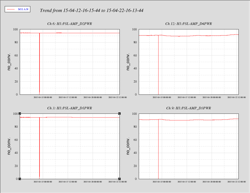
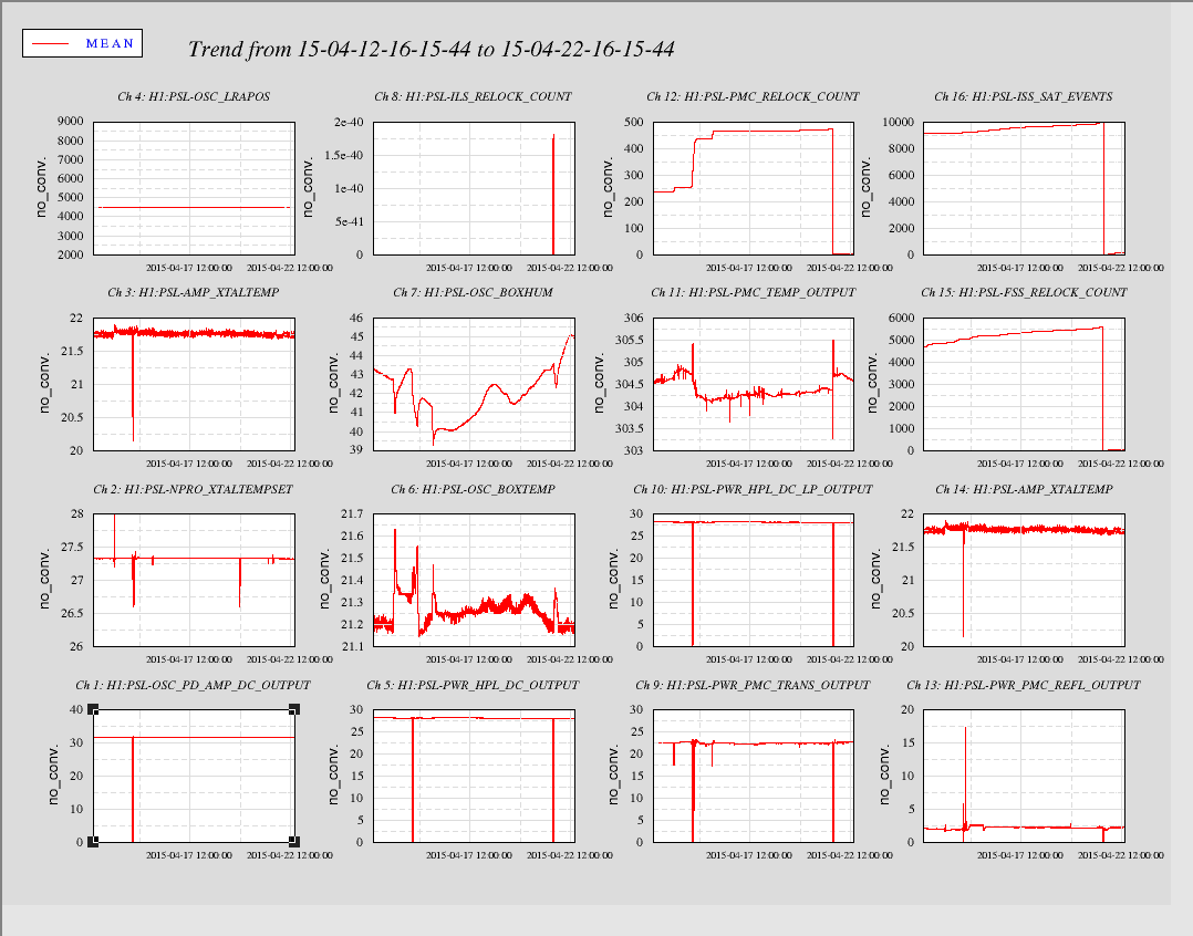
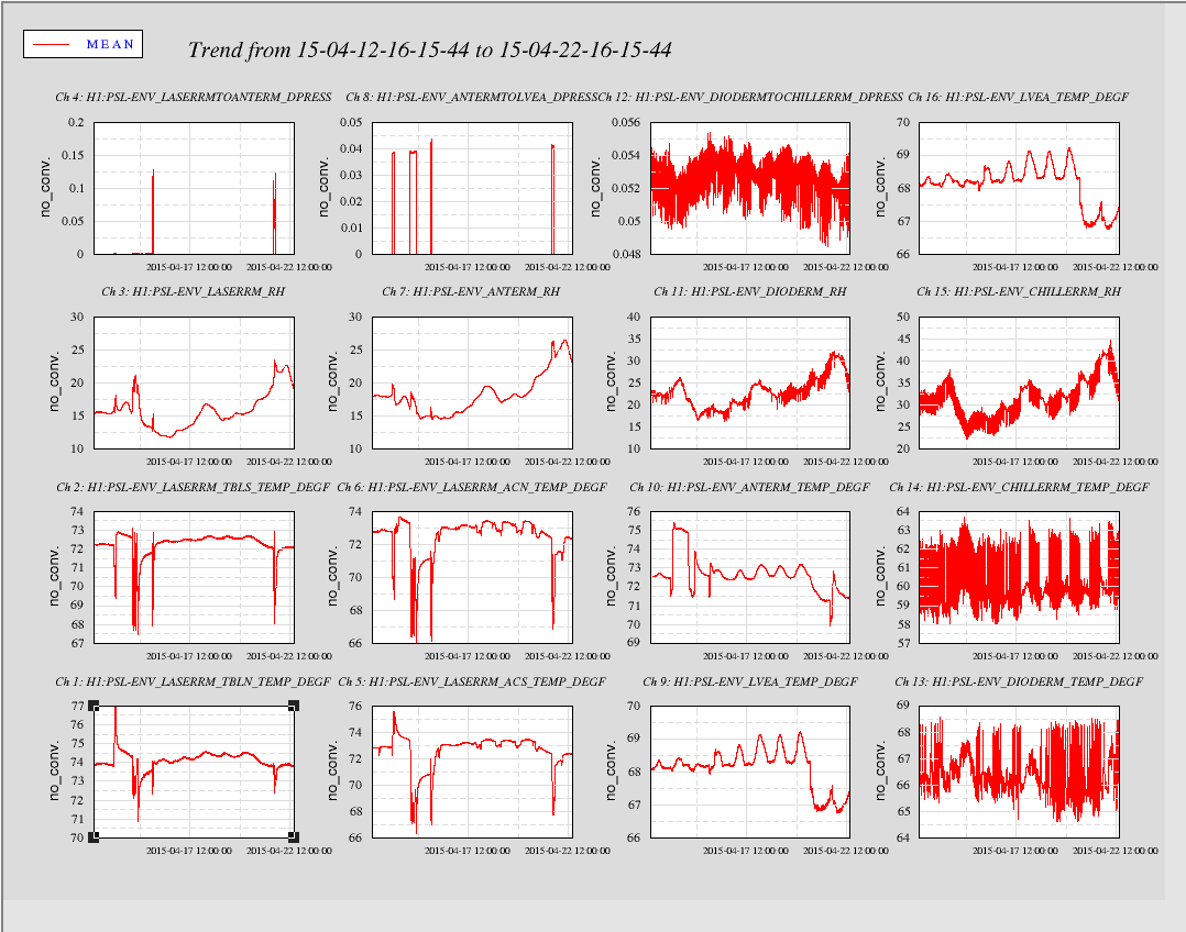
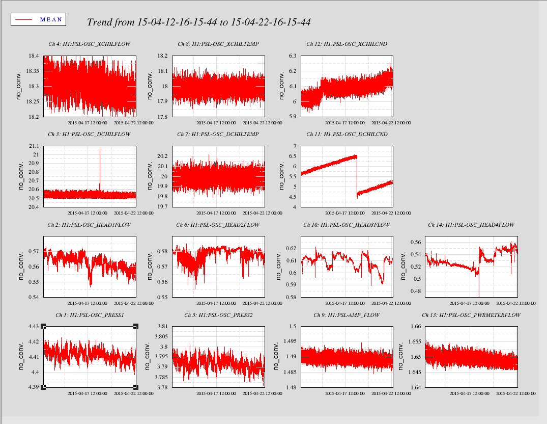
PSL DBB/ISS Scans
DBB/ISS scans for this week.
Non-image files attached to this report
DBB/ISS scans for this week.
While running DBB scans this morning I noticed the PSL ISS diffracted power was down around 3%. I adjusted the Ref Signal from 2.08 to 2.05 to bring the diffracted power up to ~7.5%.
Below are the trends from the past ten days.
SEI
Followup on STS2 install in beer garden

SUS
SDF work following RCG upgrade

CDS
STS2 installed
Coil driver swapped
Cables cleaned up
Cabling to be done for safety interlock on tables

VAC
Rebolt on site
Pickup of metal recycling
CP2 LN2 investigations

TCS
Swap of SLED

Safety meeting scheduled today
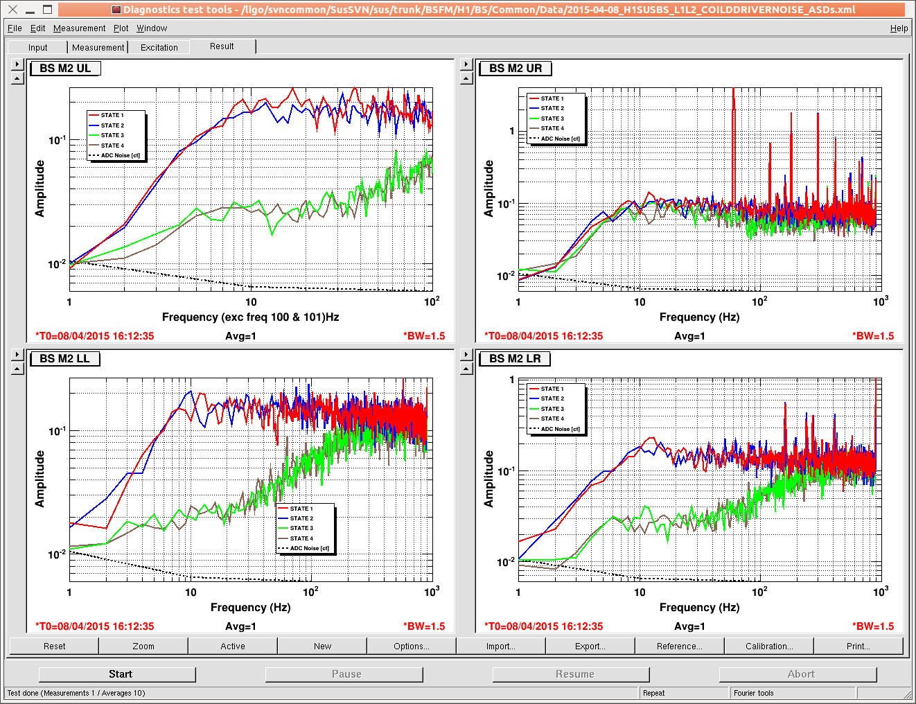
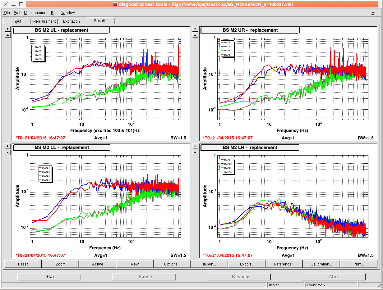
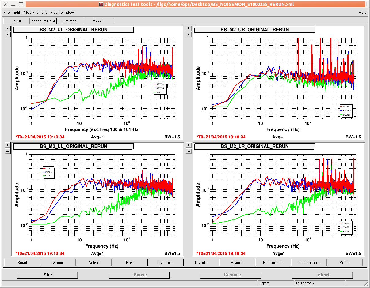
Yesterday morning the BS M2 stage coil driver was swapped out with a spare in an attempt to improve the seemingly bad UR Noise Monitor Channel. The swapped showed a similar condition, only in the LR Channel. As the test plan for TACQ Coil Drivers doesn't require testing of these circuits, we have no data to correlate these issues. However, when the original coil driver was replaced back into service and re-tested, the resulting measurements were reasonably identical to the original measurements. This seems to be a strong indication that the issue is a condition of the monitor bd in the chassis and not cabling/AA/ADC channels, etc. The far left image is the original spectra for the BS M2 stage. The middle image is the spectra for the substitute coil driver. The far right image is the spectra for the original coil driver after re-install.
Nutsinee, Elli
HWS plates replaced on ETMX and ETMY HWS. We shifted the beam path on the ETMX HWS path to get the dimmer refection from a wedge, to drop the power on the HWS. (This is now the lowest power we can get with the current optics.) The power level onto ETMX HWS looks good, the CCD is mostly unsaturated with the plate on. I have changed the exposure time to 13000microseconds, down 20% from the previous 16000microseconds setting. There are about 30 saturated pixels at this setting. ETMY HWS image is too saturated.
ITMY HWS path is aligned to the green beam again. (This alignment changes every time the SR2 and SR3 alignments change). However the ITMY SLED is dead. We need to swap out this SLED and adjust the maximum power levels on the ITMX and ITMY sleds.
Greg, Nutsinee, Aidan, Elli
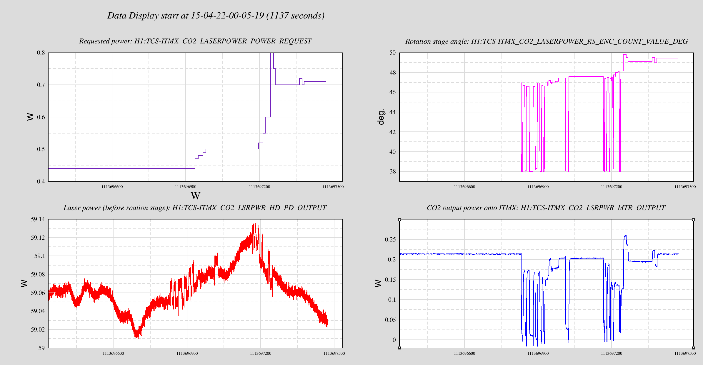
In the current configuration, the ITMX CO2 laser is inputting 0.2W of central heating to ITMX, just as it has been doing so for the last few months. The power put onto ITMX is still 0.2W, as measured by the power meter on the CO2X table (H1:TCS-ITMX_CO2_LSRPWR_MTR_OUTPUT). But the requested power needed to get 0.2W output in now 0.71W, up from 0.35W yesterday. The rotation stage does not appear to be returning to the same location.
Details:
The CO2 laser power is requested by a setting H1:TCS-ITMX_CO2_LASERPOWER_POWER_REQUEST to the desired value, and then a rotation stage moves a 1/2 wave plate to the required angle for that power. After the model restart this morning, we had to request a very different power (0.44W this morning compared to 0.35W yesterday, compared to 0.3W in March) to get the same output power in H1:TCS-ITMX_CO2_LSRPWR_MTR_OUTPUT. None of the gains or calibration values had changed this morning, so we suspect hysteresis in the rotation stage. I moved the rotation stage back and forth between minimum power and 0.2W output power and back again. I needed to keep requesting higher powers to bring the output power to 0.2W, although there seems to be no clear pattern to the change. Perhapse the rotation stage is sticking sometimes. See attached data set of 20 mins of data where I was moving the rotation stage around.
Other comments on ITMX CO2 laser:
We noticed a few other things while trending the output power:
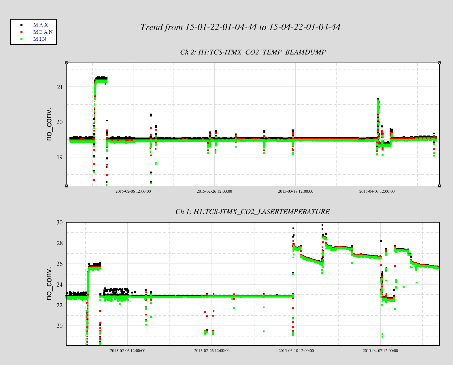
The laser temperature as measured by H1:TCS-ITMX_CO2_LASERTEMPERATURE jumped from 23 degrees Celcius to ~27C on 17 March, see plot . The temperature has been fluctuating a lot more since then. This does not corelate with the enclosure temperature, the laser power has been steady at 59W, and the chiller settings have not changed. Greg and Matt were poking around the CO2 lasers that day, although according to the alog no chages were made to the ITMX CO2 laser (alogs 17303, 17302).
The laser has been mode hopping since 10 April when Greg swapped out the CO2 laser AOM (alog 17737). We hadn't seen this previously. The laser power has been fluctuating by >1% (1W fluctuations from 59W output power). This does not have a big effect on the power level going onto ITMX.
There's a correlation between spikes in output power of the laser and shifts in the rotation stage. This is quite possible if there is a small reflection from somewhere on or after the rotation stage that is coupling back into the laser and causing the laser mode to shift.
The laser temperature shift may be a glitch in the electronics box. Rich and I noticed something similar at LLO but we could never identify exactly where it came from and then it seemed to disappear. We'll look into this some more.
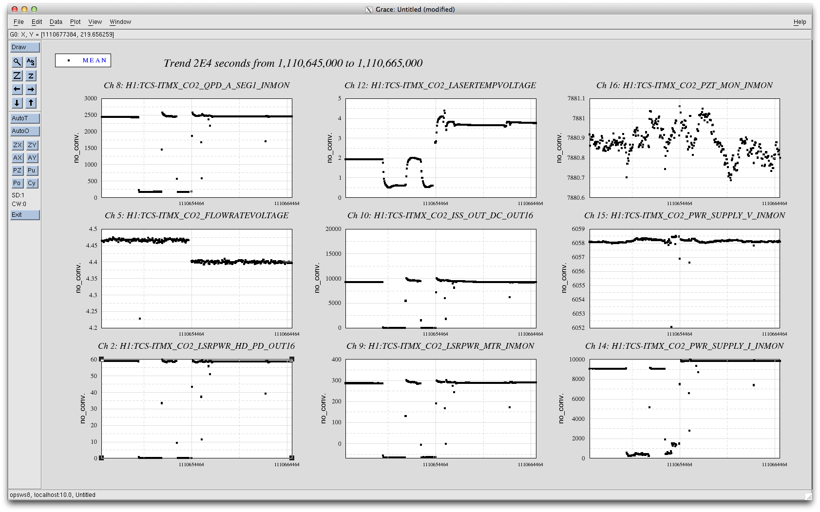
There definitely seems to be an electronics glitch associated with the laser interlock controller (D1200745). If we look at the attached plot from about a month ago, we see that during an event where the laser was turned off and back on again, there were jumps in the flowrate and temperature voltage monitors (both of which run through D1200745) at the same time that there was a 10% increase in the current to the laser. The laser interlock controller is connected to the laser RF driver to turn the laser on and off.
Taking a look at the laser head output, I'm not sure that those glitches are the laser mode hopping. The power doesn't look like it jumps as much as you would expect for a mode hop. I suspect Aidan is correct that it may be reflecting back into the laser a little which can cause some weird effects since the reflected beam can steal gain.
RCG2.9.1 upgrade [WP5158]
Daniel, Betsy, Jeff, Jim, Dave:
we upgraded all H1 models to RCG tag version 2.9.1 this morning. The H1.ipc file was created from scratch, which removed 24 obsolete IPC channels. Daniel performed an ODC common model change. The end stations models were restarted several times to resync to the ipc file. Some duplicate channels were found in the end station CAL models, these were resolved with explicit EX,EY naming.
h1psliss model core dumped during an SDF table load. More details in earlier posting. We tried to reproduce this error on the DTS x1psl0 ISS model, were unable to do so.
Two 18bit DACs were discovered to have failed their autocal, details in earlier posting.
PSL ODC update [WP5157]
Dave:
The ODC component of the h1psliss model was modified: EPICS part of CHANNEL_OUTMON changed to unsigned integer part, CHANNEL_OUT data type changed to UNIT32. Change went in when PSL was restarted today, this closed WP5157.
I checked that all fast ODC DQ channels in the DAQ are now of data type 7 (unsigned integer 32 bit)
The rather lengthy restart log is attached
Following the discovery of an 18bit-DAC which fails its autocal in x1susex, I moved the card within the chassis to see if the DAC autical failure follows the card. It does.
On inspection, this 18bit DAC differs from the other 4 in the chassis in that the S/N label on the solder side is smaller and placed closer to the front of the card. When we next open the h1susb123 and h1sush56 IO Chassis, we should check if those cards are visually different as well.
Entry by Kyle
LLCV % open for CP2 increased by 20% of its traditional output ~ 10 days ago for some reason -> today's delivery resulted in slow response (shouldn't be related) -> xfer line likely will warm up tonight before PID settles -> delivery rate wasn't abnormally short -> uncertain why response is different -> will investigate
This entry by John
This is likely due to the extra draw on the CP2 dewar after connecting all the 3IFO storage containers to N2 purge. The dewar pressure is probably falling but we should be able to reduce the storage purge.
If not we can use the self pressurizing circuit of the dewar to increase the boiloff.
JasonO, KiwamuI, RickS (and RobertS, in spirit)
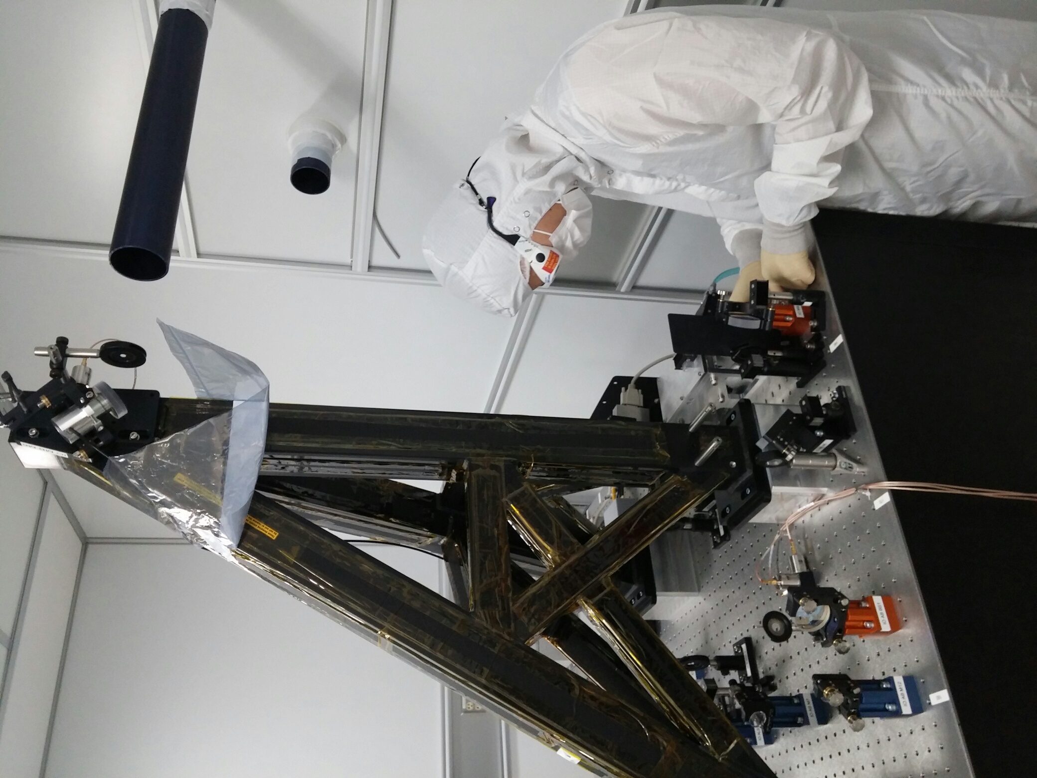
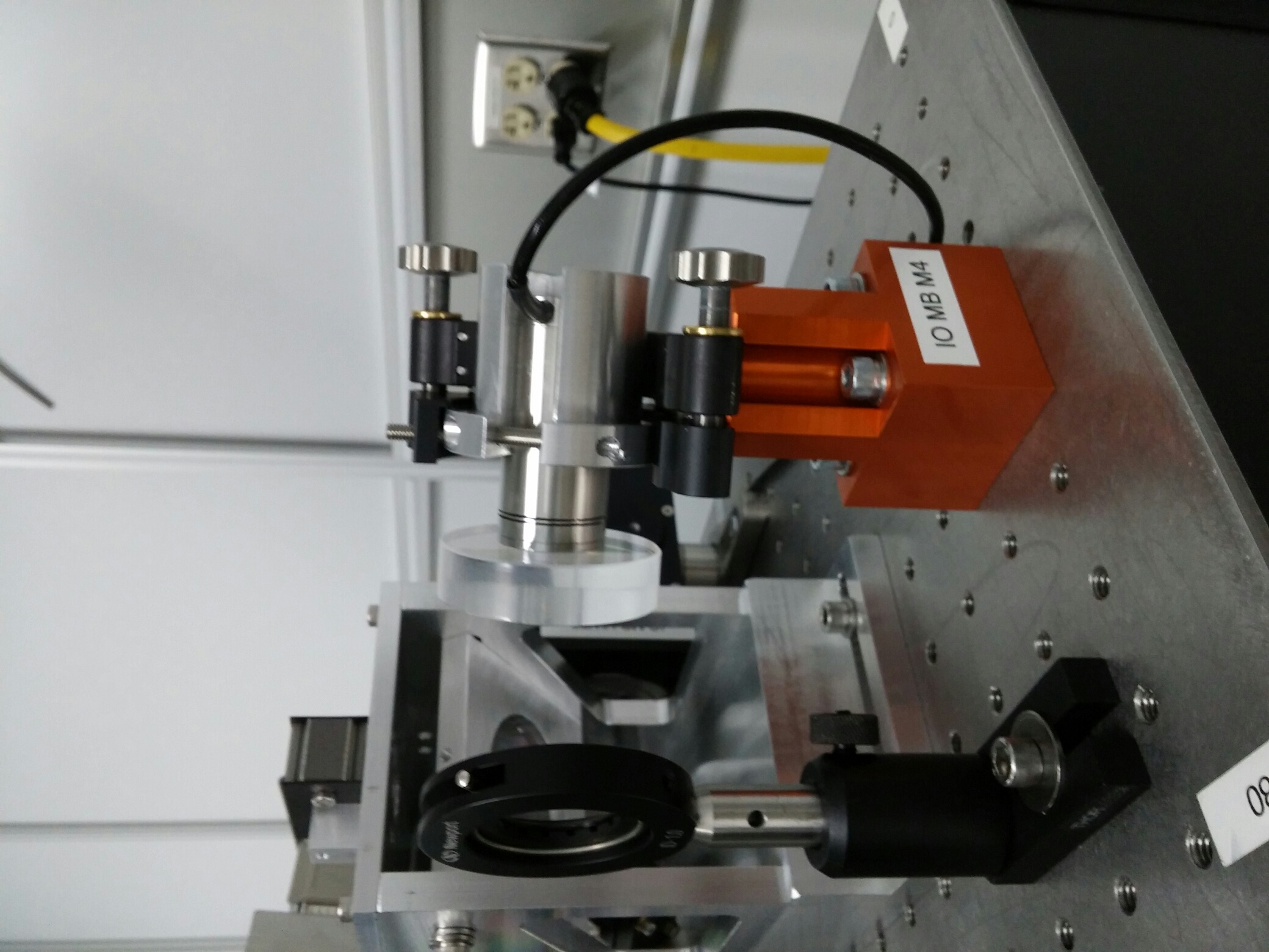
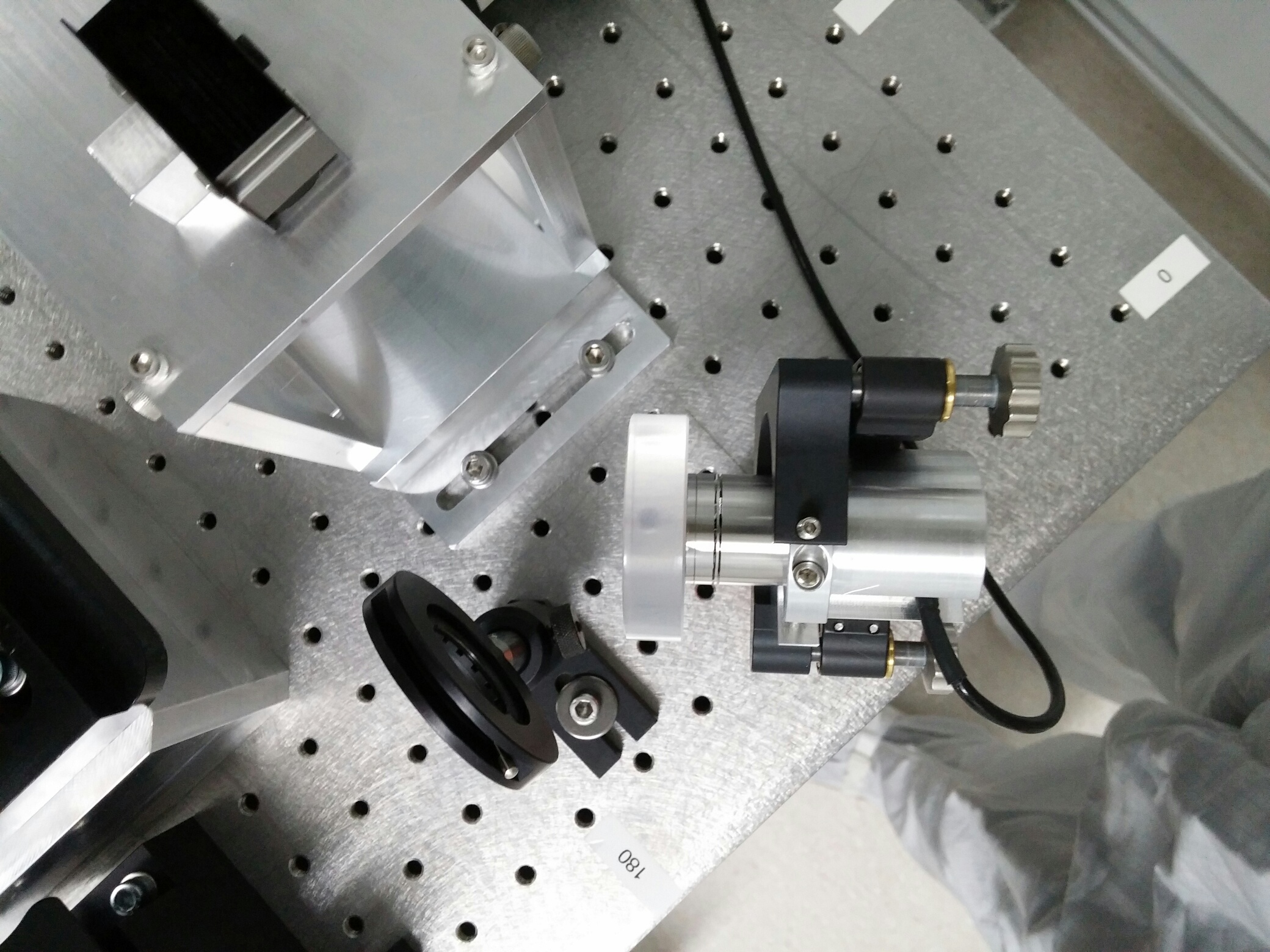
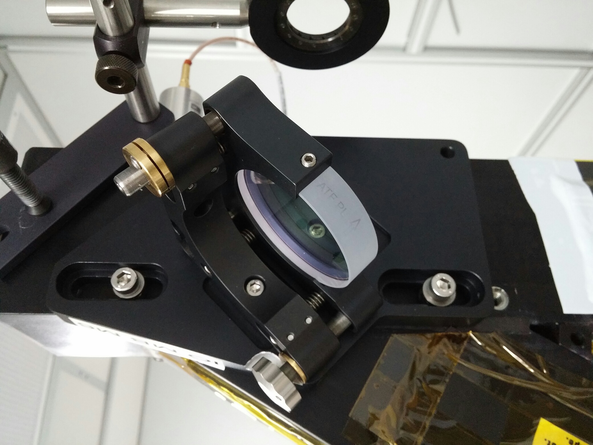
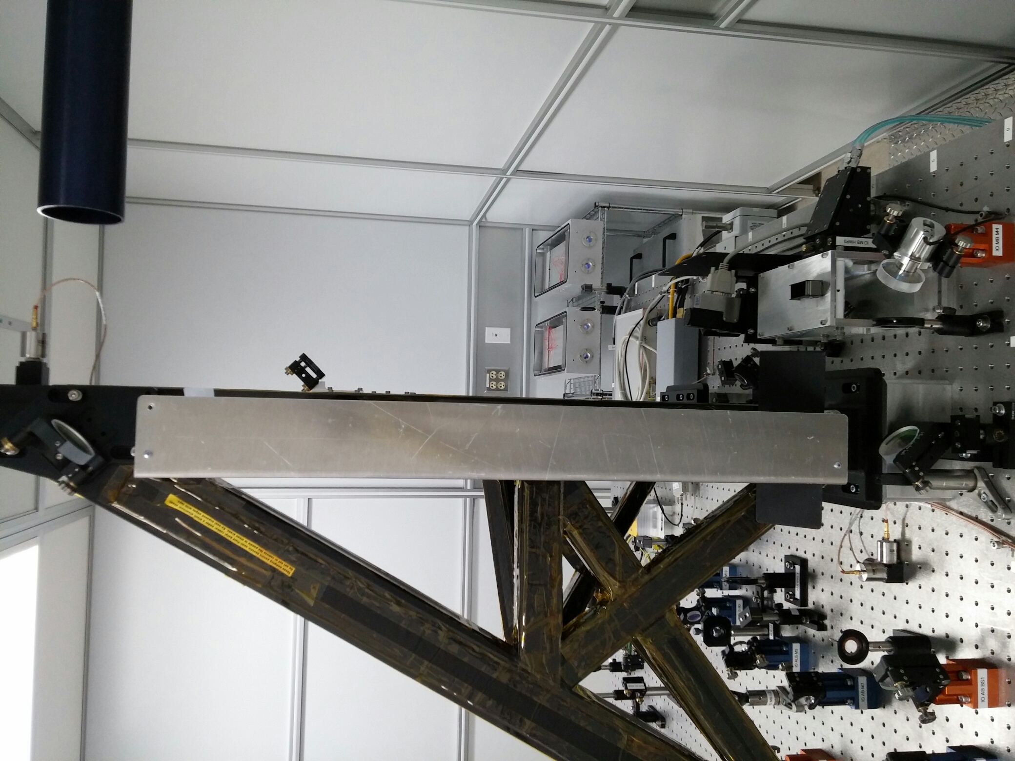
Today, we moved the PZT-controlled mirror from the top of the IO periscope down to the surface of the optical table and swapped it with with a turning mirror that was on the table. I.e. IO_MB_M6 (top of periscope) swapped with IO_MB_M4 (turning mirror immediately downstream of thin-film polarizers). Note that the PZT blocks the (weak) beam transmitted through the mirror, so we removed beam dump IO_MB_BD6.
We first installed an iris at the top mirror ouput, using a C-clamp to attach a temporary plate to the top of the periscope.
We removed the top mirror mounting plate, installed a remporary Ameristat skirt using cleanroom tape, and used a single-edge razor blade to remove some of the periscope damping material. This allowed the top plate to drop down to the required position.
We swapped the pitch actuator on the upper mirror mount to use a non-lockable actuator that doesn't interfere wtih the mounting plate.
We then used existing irises on the table in the path transmitted by the bottom periscope mirror and the iris we installed plus the spot on the outside of the PSL enclosure that reflects from the HAM1 input port to align the two mirrors we swapped.
We were able to re-install the protective shield for the vertical path up the periscope in it's original orientation.
We expect that RobertS will assess whether or not this reduced noise induced by the PZT mirror by not having it at the top of the periscope where the noise is amplified by the periscope resonance.
A few images are attached below.
Some comments from point of view of the IMC control.
After today's upgrade to RCG 2.9.1 we looked to see if the DAC AUTOCAL was successful using these procedural notes. The last check was done on the BSCs only a few weeks ago (alog 17597). During today's check, we found errors on h1susb123 again and also on h1sush56. Both show that the AUTOCAL failed for 1 of their DACs. As well, Kissel logged into LLO and found all AUTOCALs reported SUCCESS on all SUS front ends since their last computer restart.
The LHO errors were as follows:
controls@h1sush56 ~ 0$ dmesg | grep AUTOCAL
[ 60.359217] h1iopsush56: DAC AUTOCAL SUCCESS in 5134 milliseconds
[ 65.510812] h1iopsush56: DAC AUTOCAL SUCCESS in 5134 milliseconds
[ 70.661410] h1iopsush56: DAC AUTOCAL SUCCESS in 5134 milliseconds
[ 75.813017] h1iopsush56: DAC AUTOCAL FAILED in 5134 milliseconds
[ 80.963620] h1iopsush56: DAC AUTOCAL SUCCESS in 5134 milliseconds
[8443363.521348] h1iopsush56: DAC AUTOCAL SUCCESS in 5134 milliseconds
[8443368.669944] h1iopsush56: DAC AUTOCAL SUCCESS in 5133 milliseconds
[8443373.818544] h1iopsush56: DAC AUTOCAL SUCCESS in 5133 milliseconds
[8443378.967145] h1iopsush56: DAC AUTOCAL FAILED in 5133 milliseconds
[8443384.115739] h1iopsush56: DAC AUTOCAL SUCCESS in 5133 milliseconds
The first of the 2 above calibrations was the reboot 97 days ago, on Jan 14, 2015 when we upgraded to RCG 2.9.
________________________________________________________________
controls@h1susb123 ~ 0$ dmesg | grep AUTOCAL
[ 61.101850] h1iopsusb123: DAC AUTOCAL SUCCESS in 5134 milliseconds
[ 66.252460] h1iopsusb123: DAC AUTOCAL SUCCESS in 5134 milliseconds
[ 71.833569] h1iopsusb123: DAC AUTOCAL SUCCESS in 5133 milliseconds
[ 77.416848] h1iopsusb123: DAC AUTOCAL SUCCESS in 5134 milliseconds
[ 82.567454] h1iopsusb123: DAC AUTOCAL SUCCESS in 5134 milliseconds
[ 87.718046] h1iopsusb123: DAC AUTOCAL SUCCESS in 5134 milliseconds
[ 92.869668] h1iopsusb123: DAC AUTOCAL SUCCESS in 5134 milliseconds
[ 98.021279] h1iopsusb123: DAC AUTOCAL FAILED in 5134 milliseconds
[6643697.827654] h1iopsusb123: DAC AUTOCAL SUCCESS in 5134 milliseconds
[6643702.976255] h1iopsusb123: DAC AUTOCAL SUCCESS in 5133 milliseconds
[6643708.553386] h1iopsusb123: DAC AUTOCAL SUCCESS in 5134 milliseconds
[6643714.130498] h1iopsusb123: DAC AUTOCAL SUCCESS in 5134 milliseconds
[6643719.278911] h1iopsusb123: DAC AUTOCAL SUCCESS in 5133 milliseconds
[6643724.427687] h1iopsusb123: DAC AUTOCAL SUCCESS in 5134 milliseconds
[6643729.576295] h1iopsusb123: DAC AUTOCAL SUCCESS in 5133 milliseconds
[6643734.724703] h1iopsusb123: DAC AUTOCAL FAILED in 5133 milliseconds
[8443632.920341] h1iopsusb123: DAC AUTOCAL SUCCESS in 5133 milliseconds
[8443638.069031] h1iopsusb123: DAC AUTOCAL SUCCESS in 5133 milliseconds
[8443643.646215] h1iopsusb123: DAC AUTOCAL SUCCESS in 5134 milliseconds
[8443649.223336] h1iopsusb123: DAC AUTOCAL SUCCESS in 5134 milliseconds
[8443654.371885] h1iopsusb123: DAC AUTOCAL SUCCESS in 5133 milliseconds
[8443659.520452] h1iopsusb123: DAC AUTOCAL SUCCESS in 5134 milliseconds
[8443664.669135] h1iopsusb123: DAC AUTOCAL SUCCESS in 5133 milliseconds
[8443669.817631] h1iopsusb123: DAC AUTOCAL FAILED in 5133 milliseconds
The first of the 3 above calibrations was the reboot 97 days ago, on Jan 14, 2015 when we upgraded to RCG 2.9, then a restart/calibration by Kissel April 1 (mentioned above), then today's RCG 2.9.1 upgrade.
J. Kissel, B. Weaver, D. Barker, R. McCarthy, and J. Batch

We've traced down which suspensions are *using* these DAC cards that always fail their calibration: susb123's is used by the ITM ESD, and sush56's is used by the bottom stage of SR3. Both are currently not used for any local or global control, so we don't *think* this should cause any glitches.

@DetChar -- can you confirm this? I'm worried that when the DAC *noise* crosses zero, then there are still glitches.

Further -- Dave has confirmed that there are 18-bit DAC on the DAQ Test stand which fail the calibration, and those cards specifically appear to be of a different generation board that the ones that pass the calibration regularly. We suspect that this is the case on the H1 DAC cards as well. However, because they're not used by anything, we figure we'll wait until we *have* to swap out the SUS DACs for the newer-better, fixed-up EEPROM version of the board to investigate further.

That's the plan so far. Stay tuned!
Detchar would like to request that the HWS cameras in the center building be turned off for a few minutes at a known time. We're trying to track down some glitches in PEM and ISI sensors that happen every second, and Robert suspects the HWS. Just a few minutes with them off, and then on again, would be fine; we don't need the IFO to be in any particular state, as long as the ISIs are running fine. We would need the precise times (UTC or GPS preferred), as the channels that record the camera state don't seem trustworthy (alog).
This afternoon I tunred all HWS off and I will leave them off all night (both of the corner station HWS were on prior to this).
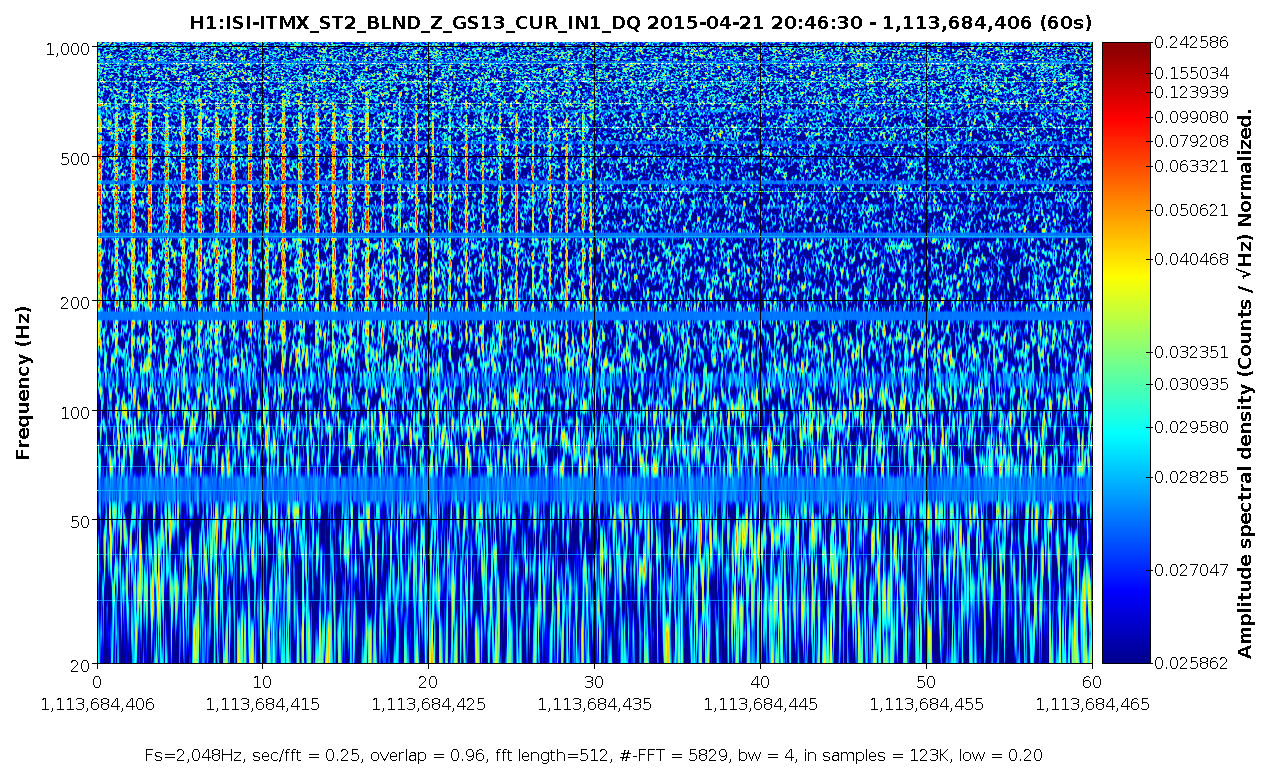
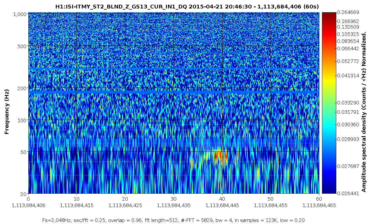
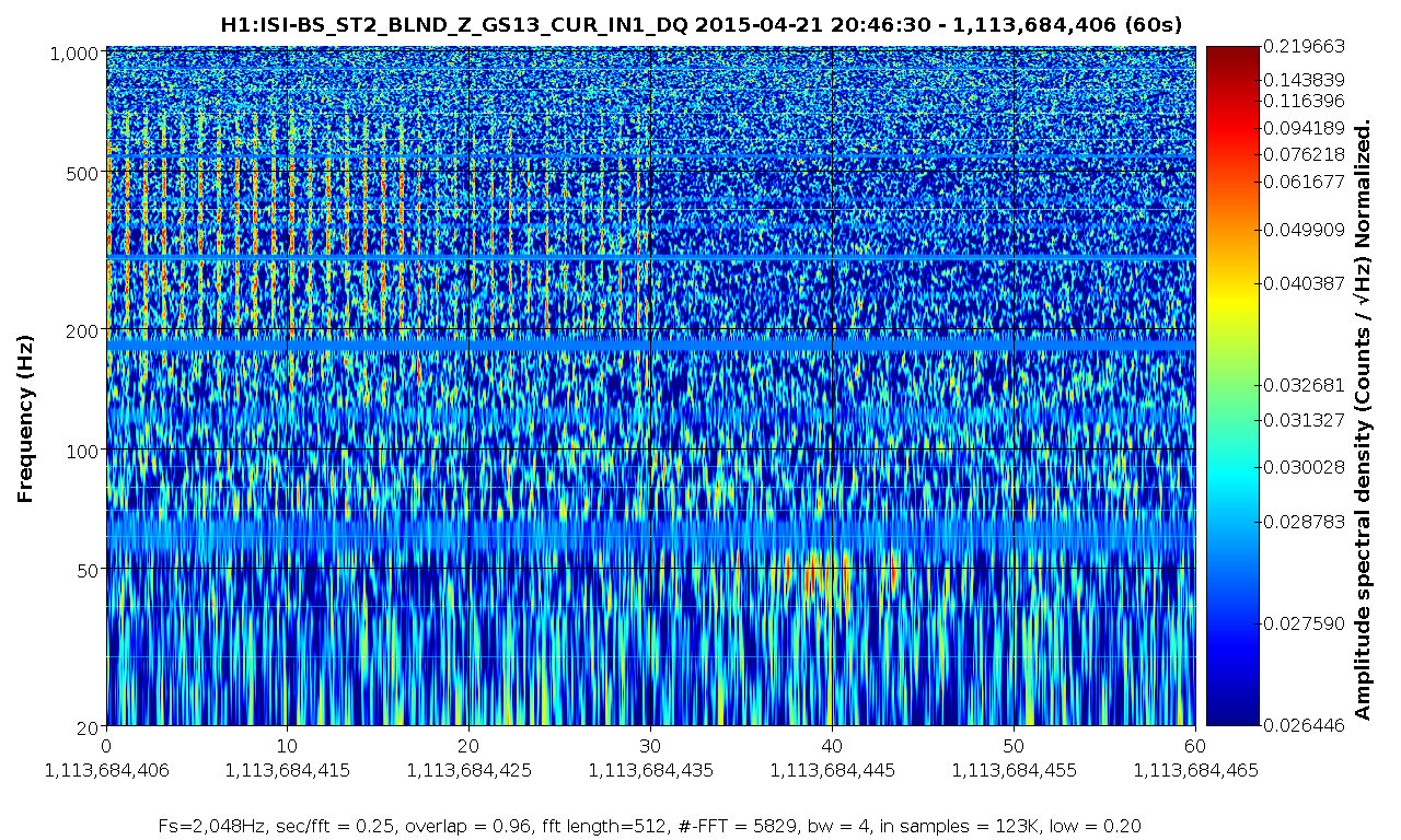
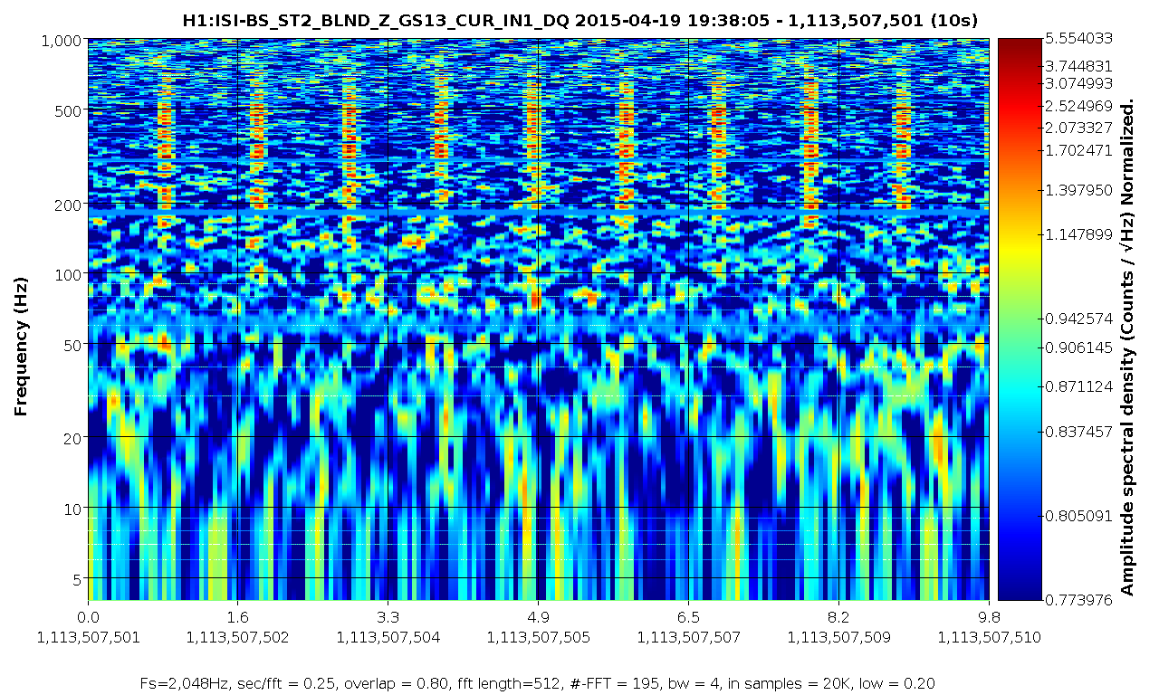
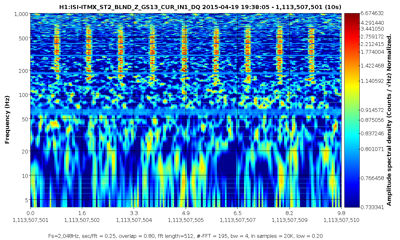
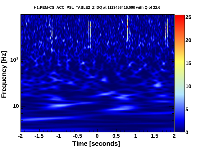
It seems like the HWS was in fact the culprit. The HWS was turned of at Apr 21 20:46:48 UTC, according to TCS-ITMX_HWS_DALSACAMERASWITCH. I checked the BLND_Z of the GS13s on BS and ITMX, and the table 2 PSL accelerometer. All three had glitches every second before the HWS was turned off. They all continued to glitch for 11 more seconds (until the end of the minute), and then all stopped at the exact same time.

Attached is a spectrogram of the ITMX GS13. It's hard to see the glitches in the PSL by spectrogram or even Omega scan, but they're very apparent in the Omicron triggers.
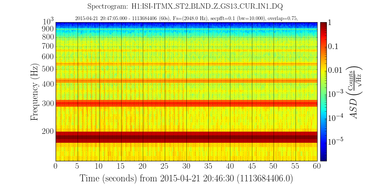
Here are three better spectrograms showing the transitioning off of the HWS and the loud once per second glitches going away in the ISI-*_ST2_BLND_Z_GS13_CUT_IN1 channels. These plots are made with https://ldvw.ligo.caltech.edu using 0.25 seconds per FFT and normalization turned on. Conclusions same as Andy's post above.
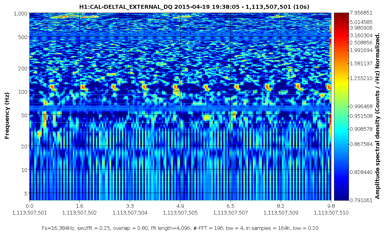
David Shoemaker asked the good question, do these glitches even show up in DARM? Well, that's hard to say. There are once per second glitches that show up in the ISI channels, and once per second glitches that show up in DARM. We don't know if they have the same cause. Figures are: 1. DARM once per second glitches, 2,3, BS and ITMX, 4. overlay of all showing that the glitches in DARM are just slightly ahead in time (in this 0.25 sec/fft view, unless there is some sample-rate timing bias).
In order to test whether they are both caused by the HWS it would be really useful if folks on site could turn the HWS on, then off, for a minute or so in each configuration during a low-noise lock and record the UTC times of those states.
We got to a low noise state which is not at as low noise as our best, with the spectrum about a factor of 10 worse at around 90 Hz than our best reference. We were in low noise, HWS off from 10:42:30 UTC to 10:47:30 UTC, i turned the cameras on according to Elli's instructions and we left the cameras on from 10:48:20 UTC to 10:53:40.
J. Kissel, K, Izumi

I had started the weekend hoping to improve the DARM calibration in the following ways:
(1) Including the compensation for the analog and digital anti-aliasing (AA) and anti-imaging (AI) filters.

(2) Decreasing the DARM coupled cavity pole by 25% to 290 [Hz].

(3) Establishing an uncertainty estimate of the optical gain (the DC scale factor component of the sensing function).

(4) Reducing the delay time in the actuation from four 16 [kHz] clock cycles to one 16 [kHz] clock cycles.

After study, and Sunday's improvement to the power recylcing gain, we've decided not to make *any changes to the calibration, yet.
However, for the record, I put down what I've studied here, so we can begin to understand our uncertainty budget.

%% Details
-----------
(1) Including the compensation for the analog and digital anti-aliasing (AA) and anti-imaging (AI) filters
LLO has pioneered a method to compensate for the high frequency effects of the analog and digital (or IOP) AA and AI filters, by including the *product* of all four filters in the actuation chain of the front-end CAL-CS model (see the last few pages of G1500221 and LLO aLOG 16421).

Further, Joe has analyzed a collection of 281 real, analog AA/AI filters that were tested during CDS acceptance testing to refine the exact frequency response of these filters (see first attachment, aLIGO_AAAI_FilterResponse_T1500165.pdf). In summary, the 3rd order Butterworth's corner frequency is statistically significantly lower; measured to be 8.941 (+0.654 /-0.389 or +7%/-3%) [kHz] instead of the ~10 [kHz] Butterworth model that we have been using (which was inherited from a .mat file the 40m). Though this does not appreciably affect the magnitude error at high-frequency, it does as much as 3 [deg] of phase by 2 [kHz], which can throws off our estimate of the residual unknown time delay by 5 [us] when we try to account for it in our fitting of the open loop gain transfer function.

However, after exploring what LLO has implemented, we've discovered a flaw in the implementation of this compensation. In going from the continuous zpk model of the filters to discrete, because we're trying to model these filters which have all of their response near, at, or above the Nyquist frequency, there is significant difference of modeled filter's response between the continuous and discrete models (see second attachment 2015-04-18_AAAI_FilterStudy.pdf).

As such, we will *not* begin to compensate for the AA and AI filtering until we arrive at a better method for compensating these filters.

(2) Decreasing the DARM coupled cavity pole by 25% to 290 [Hz].
Over the past few weeks, we've established the DARM coupled cavity pole is now at 290 [Hz] instead of the predicted L1 value of 389 [Hz] (see LHo aLOG 17863). We've added one more DARM open loop gain transfer function to the list we're now comparing after the HAM6 vent,
Apr 13 2015 04:15:43 UTC % Post HAM6 Vent & UIM/TST Crossover; 10 [W] input power
Apr 13 2015 06:49:40 UTC % No loop parameter changes, but input power 15 [W]
Apr 15 2015 07:53:56 UTC % Input Power 15 [W] no change in control system from previous measurement
with these three measurements, I made a statistical comparison of the model / measurement residual while using 290 [Hz] for the modeled coupled cavity pole frequency, and reducing the unknown time delay from 40 [us] to 30 [us] because I've used Joe's measured mean for the  analog AA / AI in the model (see third attachment 2015-04-18_290HzCCP_H1DARMOLGTF.pdf ). As one can see on the 3rd and 4th page, assuming each of the residuals frequency points is a measurement of the the true OLGTF value with a Gaussian distribution, the uncertainty in the frequency dependence of the OLGTF model is now a 1-sigma, 68% confidence interval of +/- 1.5% in magnitude and 1 [deg] between 15 and 700 [Hz] (IF we change the CCP frequency to 290 [Hz], compensate for the AA and AI filters, and include 30 [us] of unknown delay). Note that this assumption of Gaussianity appears to be roughly true for the magnitude, but not at all in phase (I'm still thinking on this). Also note the each one of these frequency points has passed a 0.99 coherence threshold on a 10 [avg] measurement (and most have coherence above 0.995), so the individual uncertainty for each point is sqrt((1-coh)/(2*nAvgs*coh)) = 1 to 2%.

Recall the frequency dependence of the model is determined by the following components included in the model:
- The 1/f^2 dependence of the [m/N] suspension transfer function (as modeled by the QUAD state space model)
- The 2000 [Hz] ESD driver pole
- The analog and digital anti-imaging filters
- The 130 [us] of actuation delay from 1 16 [kHz] cycle of SUS Computation, 3 65 [kHz] cycles of IOP Error Checking, 1 65 [kHz] cycle of IOP Computation, and 1/2 65 [kHz]  cycle for Zero-order Hold Delay
- The DARM filters
- The single-pole response (at 290 [Hz]) of the optical plant
- The analog and digital anti-aliasing filters
- The 76 [us] of sensing delay from 1 65 [kHz] cycle of IOP Computation, 1 16 [kHz] cycle of OMC Computation
- The 30 [us] of unknown time delay

As a cross-check, I recalculated the comparison with the CCP frequency that's currently used in the model, 389 [Hz], and found that at around the high-frequency PCal lines, roughly ~535 [Hz] the model / measurement discrepancy is 25-30%. This is consistent with what the PCAL calibration reports at these frequencies, a DARM / PCAL (which is equivalent to model / measurement) discrepancy of 25-30% -- see LHO aLOG 17582. At the time, the PCAL team reports their internal uncertainty to be in the few-percent range.

This had convinced me on Saturday that I had enough information to "officially" change the DARM CCP frequency in the CAL-CS front end, but Gabriele and Evan have since changed the alignment scheme for the corner station to improve the power recycling cavity gain by improving the ITM DC alignment LHO aLOG 17946. This will have an effect on the signal recycling cavity and therefore the DARM CCP frequency, so we'll wait until we get a few more OLGTFs in this new configuration before changing anything.

(3) Establishing an uncertainty estimate of the optical gain (the DC scale factor component of the sensing function).
After refining the precision of the frequency dependence in magnitude, this allows to quantify the precision to which we can estimate the overall DC scale factor that one needs to scale the model to the measured OLGTF; a factor that we traditionally have attributed only to the change in optical gain between lock stretches. For this study, I've used *all* six DARM OLGTF TFs, see 2015-04-18_AllMeas_FittedCCP_H1DARMOLGTF.pdf. Note that this increases the uncertainty of the frequency dependence to a less Gaussian 2.5%, but as you'll see this is still plenty precise.

Recall that before transition to the OMC DCPDs, regardless of input power to the IFO, the OMC_READOUT sensor gain is changed to match the RF readout sensor gains which are already power normalized. That should mean that input power should have no affect on the measured optical gain, and this is a safe comparison.

With 6 measurements, the mean scale factor for the OLG TFs is 1.05e6 +/- 26% [ct / ct]. This is consistent by the variation the DARM digital gain by 34% that was used for these 6 measurements. The current optical gain used for the sensing function the CAL-CS front end model is 1.1e6 [ct/m]. This 4% difference from the mean of the these 6 measurements is well within the 26% uncertainty, so we've concluded to *not* change anything there.

All this being said, we have used the *same* actuation strength for all of these comparisons, but there is no guarantee that the actuation strength is not changing along with the optical gain.
- ETMY is controlled using the Test Mass (L3) and UIM (L1) stages
- The cross-over for these two stages in the two groups of measurements is ~1.2 [Hz] and 2.5 [Hz] (see 17713), and by 10 [Hz], the contribution of the UIM is roughly -25 [dB] and -15 [dB]. Therefore the ESD is the dominate actuator in the frequency region which we're we trying to
- Static charge affects the actuation strength of the ESD by changing the effective bias voltage of the drive, as well as changing the amount of drive that's in the longitudinal direction (because the charge can migrate to different regions of the reaction mass / test mass gap), see e.g. G1500264, LLO aLOG 16611, or LLO aLOG 14853.
- If there is substantial residual charge on the ESD, the charge varies on the the ESD when Ion Pumps are valved into the chamber.
- It has been shown many times over that the charge varies on the few hour time scale when there is significant residual charge on the test mass and the ion pumps are valved in (see e.g., G1401033 or as recently as LLO aLOG 17772).
Thus, it is reasonable to suspect that the actuation strength is changing between these measurements. LHO has made no-where-near enough measurements (only a one-time comparison between ETMX and ETMY, see LHO aLOG 17528) to quantify how much this is changing, but here is what is possible:
- We have a physical model of the actuation strength (or at least more accurate equation for how the bias voltage determines the actuation strength, see above citations). I think we can take what we've seen for the variance (as high as +/- 400 [V] !!) and propagate that through to see how much of an affect it has on the strength
- PCAL lines at low-frequency (~30 [Hz]), compared against the DARM calibration lines should show how the optical gain is varying with time, it's just that no one has completed this study as of yet.
- Calculation of the gamma coefficient from the DARM lines should also reveal how the open loop gain transfer function is changing with time. In the past, we've assumed that changes in gamma are fluctuations in the optical gain because we've had actuators with non-fluctuating strength.

Thus, for now, we'll incorrectly assign all of the uncertainty in the scale factor to optical gain, and call is 26%. Perhaps it will be much better to trust PCAL at this point and time, since it's precision is so much greater than this "scale the OLGTF model" method, but I would need a third measurement technique to confirm the accuracy. I think a power budget propagated to a shot noise estimate compared against the measured ASD (like in LHO aLOG 17082) is the easiest thing to do, since it can be done offline. Or we should resurrect the campaign to use the IMC VCO as a frequency reference, but this has the disadvantage of being an "offline, odd configuration" measurement, just like the free-swinging Michelson.

(4)Reducing the delay time in the actuation from four 16 [kHz] clock cycles to three 16 [kHz] clock cycles.
As mentioned above, the time delays that are included in this model are
- The 130 [us] of actuation delay from 1 16 [kHz] cycle of SUS Computation, 3 65 [kHz] cycles of IOP Error Checking, 1 65 [kHz] cycle of IOP Computation, and 1/2 65 [kHz]  cycle for Zero-order Hold Delay
- The 76 [us] of sensing delay from 1 65 [kHz] cycle of IOP Computation, 1 16 [kHz] cycle of OMC Computation
- 30 [us] of unknown time delay (the equivalent of ~8-9 [deg] of phase at 700 [Hz])
for a total of 206 [us] of delay for which we've accounted, out of the total 236 [us] that's used to produce the above frequency-dependence comparison. So, there's a total of 3.4 or 3.9, 16 [kHz] cycles of known or known+unkuown time delay, respectively. Remember that the "L/c", light-travel time delay (13 [us]) is *less* than the one 16 [kHz] SUS clock cycle (61 [us]) delay that defines when the control signal arrives at the end station over RFM IPC, so we ignore it.

Since we only have the infrastructure add the delay in the actuation paths in CAL-CS, then we can only account for the *differential* delay between the two paths. If we assign the unknown delay to the actuation side of things, then the difference in delay between the two paths is (130+30)-76 = 84 [us] = 1.3 16 [kHz] clock cycles, leaving a residual overall delay of 76 [us]. If we assign it to the sensing function, we get 130-(76+39) = 24 [us] = 0.39 16 [kHz] clock cycles, leaving a residual of 130 [us]. Since we can't do less than 1 [kHz] clock cycle, we should chose to assign the unknown delay to the actuation function, apply one 16 [kHz] cycle delay to the actuation function, and suffer the 0.3 / 16384 = 18 [us] phase difference between the sensing and actuation path, and have to account for a 76 [us] delay in offline analysis.
Your list of known delays doesn't seem to include the 13us (L/c) delay from the interferometer response (see e.g. eqn. 16 in T970101).
Daniel's right, details below. As such, the unknown time delay is 16 +/- 5 [us],
For clarity I repeat the new list of time delays:
the time delays that are included in this model are
- The 130 [us] of actuation delay from
     - one 16 [kHz] cycle of SUS Computation,
     - three 65 [kHz] cycles of IOP Error Checking,
     - one 65 [kHz] cycle of IOP Computation, and
     - one-half a 65 [kHz]  cycle for Zero-order Hold Delay
- The 89.3 [us] of sensing delay from
     - one L/c delay sensing the ETM motion in the corner,
     - one 65 [kHz] cycle of IOP Computation, and
     - one 16 [kHz] cycle of OMC Computation
- 16.7 [us] of unknown time delay (the equivalent of ~3-4 [deg] of phase at 700 [Hz])
for a total of 219.3 [us] of delay for which we've accounted, out of the total 236 [us] that's used in the model.

Details:
--------
More on the L/c time delay, as explained by Daniel:
I have said above,
"Remember that the "L/c", light-travel time delay (13 [us]) is *less* than the one 16 [kHz] SUS clock cycle (61 [us]) delay that defines when the control signal arrives at the end station over RFM IPC, so we ignore it."

Daniel agrees:
The fiber delay is n * L/c or about 20us. It doesn't matter because it is part of
the SUS cycle delay.

However, there is a sensing function delay. When you push the ETM (from the DARM actuation) it takes at least
L/c before you can measure a signal in the corner. This is a pure optical delay. This sensed control signal is indeed what we're measuring when we take an open loop gain transfer function.

For gravitational waves the situation is similar, the photons which travel forth and back in
the arm are, on average, sampling h(t) from half a round trip ago. In reality, this
is only exactly true for perpendicular incidence.

As such, we should subtract 3994.465(+/- 7e-4) [m] / 299792458 [m/s] = 13.3 [us] from the "unknown" time delay, leaving us with a timing uncertainty of 16.7 [us]. Unclear yet what the uncertainty is in this number, since thus far it's merely fit by-eye to make the phase of the OLGTF residual flat. From playing around with the number in the fit, I would suggest a 5 [us] uncertainty on this unknown timing residual.

I'll update
/ligo/svncommon/CalSVN/aligocalibration/trunk/Runs/PreER7/H1/Scripts/H1DARMmodel_preER7.m
later today to reflect this knowledge.
OMC DCPDs have uncompensated poles at 13.7kHz and 17.8kHz due to their locations above the nyquist freq.
They cause the delay of ~18.5us. The details can be found in LHO ALOG 17647
I've confirmed Koji's statement with a bode plot, though I get a better "fit" with 20 [us] delay. But the point is moot.  I'll definitely just include this in the actual frequency response of the sensing function. This brings the unknown time delay to 0 +/- 5 [us] -- wow! Let's hope we don't find out about anything else. ;-)

Also -- that means we should include this in the approximation for the super-Nyquist frequency response of the sensing function along with the digital and analog AA filters when we fix that it in the front-end.
I've reprocessed the results after adding the L/c arm delay and the OMC DCPD uncompensated high frequency poles mentioned above. Because we've replaced the equivalent unknown time delay with a known time delay of L/c 13.3 [us] and some very high-frequency poles, the results have actually changed very little and therefore the uncertainty in the frequency response of the OLGTF has changed very little:
                                   Was                     Is Now
Magnitude Residual StDev:  1.0045 +/- 0.025318       1.0043  +/- 0.025309
Phase Residual StDev:      0.4299 +/- 1.0307         0.23821 +/- 1.0534
However, there're less unknowns in the model, which is exactly what we want.

As such, I stand by my earlier statement:

As one can see on the 3rd and 4th page, assuming each of the residuals frequency points is a measurement of the the true OLGTF value with a Gaussian distribution, the uncertainty in the frequency dependence of the OLGTF model is now a 1-sigma, 68% confidence interval of +/- 2.5% in magnitude and 1 [deg] between 15 and 700 [Hz] (IF we change the CCP frequency to 290 [Hz] -- which is now probably different, and find a good discrete approximation for compensating for the OMC DCPD poles, the AA, and the AI filters). Note that this assumption of Gaussianity appears to be roughly true for the magnitude, but not at all in phase (I'm *still* still thinking on this). Also note the each one of these frequency points has passed a 0.99 coherence threshold on a 10 [avg] measurement (and most have coherence above 0.995), so the individual uncertainty for each point is sqrt((1-coh)/(2*nAvgs*coh)) = 1 to 2%.


Details:
--------
I've added the following parameters to the params files:
par.C.omcdcpdpoles_Hz = [13.7e3 17.8e3]; % LHO aLOGs 18008 and 17647

par.C.armLength.x = 3994.4704; % [m] +/- 0.3e-3; LHO aLOG 9635
par.C.armLength.y = 3994.4692; % [m] +/- 0.7e-3; LHO aLOG 11611
par.C.speedoflight = 299792458; % [m/s]
and added the following lines to the DARM model
/ligo/svncommon/CalSVN/aligocalibration/trunk/Runs/PreER7/H1/Scripts/H1DARMmodel_preER7.m

par.C.uncompensatedomcdcpd.c = zpk([],-2*pi*par.C.omcdcpdpoles_Hz,prod(-2*pi*par.C.omcdcpdpoles_Hz));
par.C.uncompensatedomcdcpd.f = squeeze(freqresp(par.C.uncompensatedomcdcpd.c,2*pi*freq));

par.t.armDelay  = mean([par.C.armLength.x par.C.armLength.x]) ./ par.C.speedoflight;
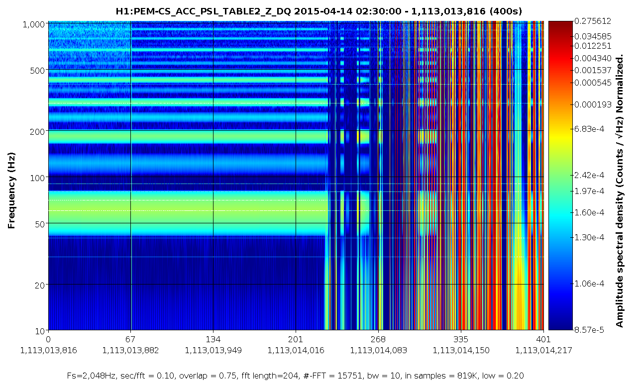
One of the accelerometers on the PSL table (PEM-CS_ACC_PSL_TABLE2_Z) is glitching once per second. The other accelerometers don't seem to have this problem. We noticed this because it was messing up our hVeto results. I searched for where these started, and as far as I can tell it's Apr 14 2:30 UTC (that's 7 PM on Monday local, I think). The onset takes a few minutes.

The first plot is an Omega scan from a few hours ago, showing the glitching. The second is a spectrogram of the onset.

We are seeing something similar in some of the ISI GS13s (maybe only ones in the center building?). They also have a once per second glitch, though it's not clear if it's related. Detchar will track that down more, and I'll alog it separately.
I have seen large 1 Hz combs in many places at the CS that are due to the Hartman Wavefront Sensor running at 1 fps (the capture rate of 57 at end stations makes a comb of huge peaks in DARM). I think that Ellie is going to keep the HWS off most of the time until we figure out why.
Do you mean a 1 Hz comb in the spectrum, or glitches every second? This is the latter. Do you have an example of what this looks like? Also, is there an easy way to tell when the HWS is on?
We're implementing a Guardian script for ETM HWS control which engages the HWS when we lock, takes a measurement during the initial transient, then turns it off after thirty minutes or so. We'll look into implementing this at the corner station too.
Longer term - we need to look into what we might be able to do to eliminate the camera noise.
The camera can be turned on and off from Beckhoff. The channels you're looking for are:
H1:TCS-ITMX_HWS_DALSACAMERASWITCH
H1:TCS-ITMY_HWS_DALSACAMERASWITCH
There are two channels to look at which are:
H1:TCS-ETMX_HWS_RCXCLINKSWITCH
H1:TCS-ETMX_HWS_DALSACAMERASWITCH

