Here is a plot of coherences with some PEM accelerometers. We have been thinking that the noise around 200-250 Hz was due to the PSL periscope PZT, based on coherences like the one in the lower left plot. However, there is suscpicously similar coherence between the ISCT6 accelerometer and DARM. Indeed, the coherence between these two accelerometers is high in this frequency range, suggesting that some cross talk could be the dominant signal in these accelerometers.
The right two panels show that the accelerometers which have coherence with DARM around 13 Hz and 16 Hz are also coherent with each other, but not nearly as much.
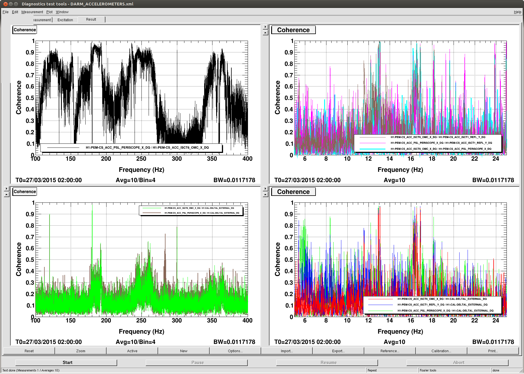
There is some cabling work that needed to be completed on this particular channel (ISCT6_ACC). Hope to bring it online on Monday.