Sheila, Alexa, Evan
Summary
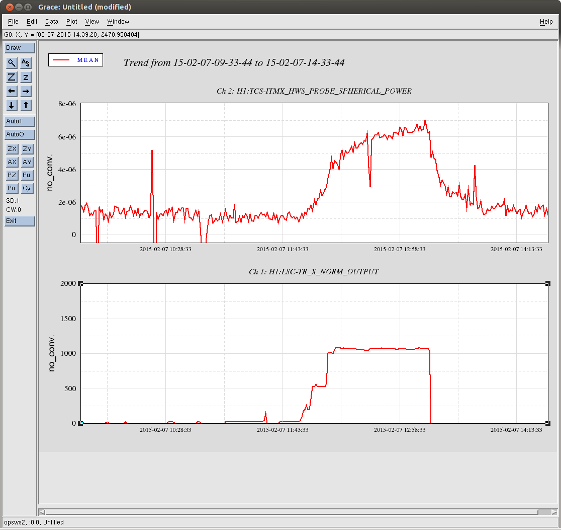
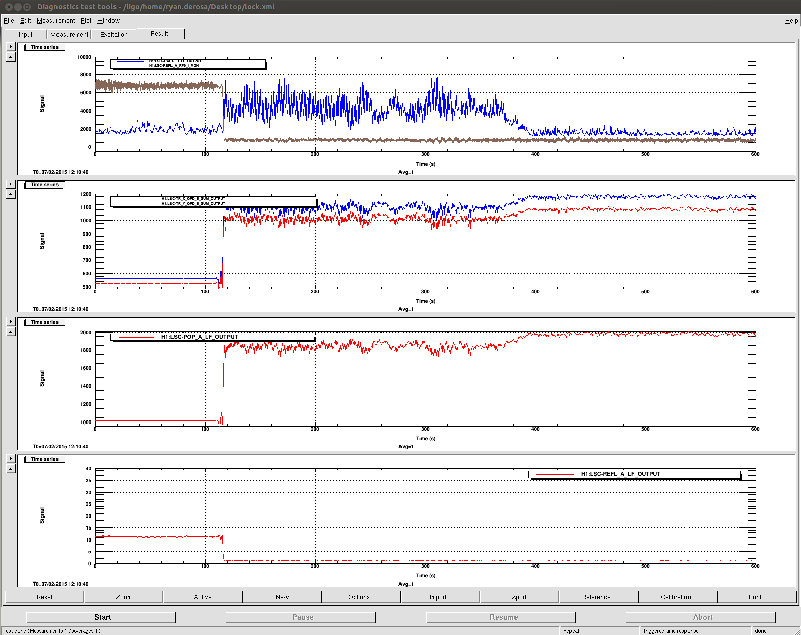
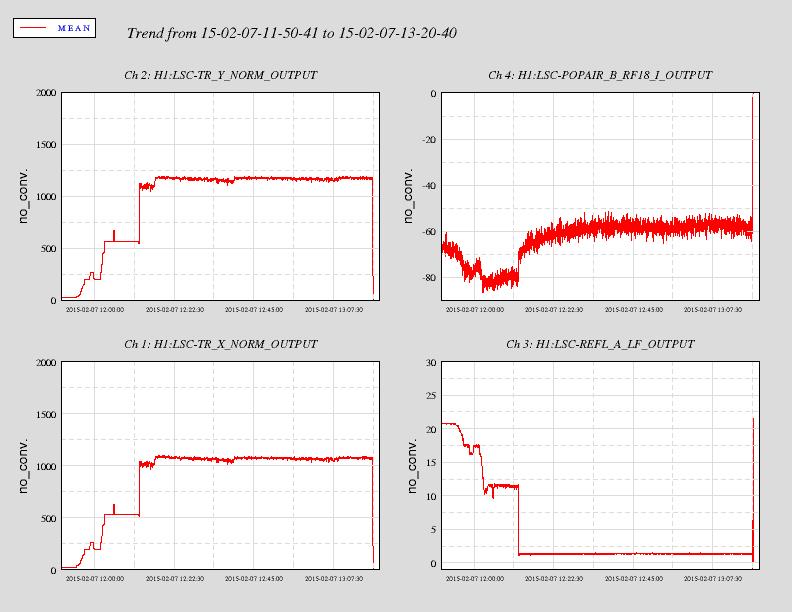
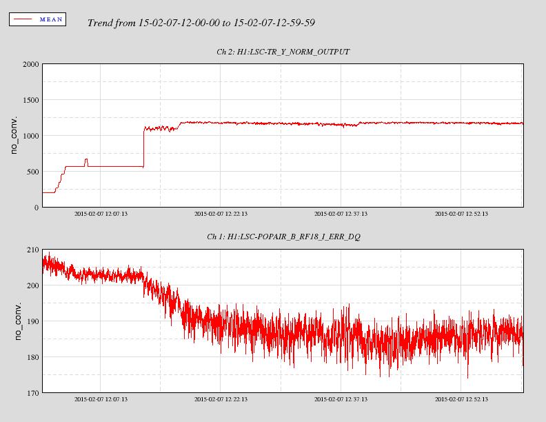
We have transitoned CARM from digital normalized REFLAIR9I to analog REFLAIR9I, with a 4 kHz bandwidth and 50 degrees of phase. An OLTF is attached [the last data point is spurious, so ignore it]. This lock started at about 2015-02-09 12:24:00 UTC. We are leaving the IFO locked.
There is plenty of phase to push the bandwidth higher, but we have encountered large offsets induced by switching on the common-mode and summing-node boards.
We can also improve the low-frequency fluctuations of the CARM error signal by introducing an integrator somewhere; we need more dc gain.
Details
Analog REFLAIR9I is plugged into input B2 on the summing-node board (SNB), with polarity "off". The output of B goes into input #2 on the common-mode board (CMB), with positive polarity. Digital normalized REFLAIR9I is plugged into input A1 on the SNB, with polarity "on". The output of A goes to input #1 on the CMB. [See LHO#16489 for a review.]
According to our reckoning, the shape of the digital CARM loop at the start of the transition is roughly 1/f above a few hertz. At a few hertz and below, it has a number of boosts and integrators which make it tricky to engineer a stable crossover with the analog signal.
Transition procedure is as follows, starting right after the guardian has brought the interferometer into resonance.
-
With the B2 gain at 0 dB on the SNB, input B2 engaged on the SNB, and the input #2 gain at 0 dB on the CMB, we engage input #2.
-
Step up B2 gain to 8 dB on the SNB.
-
Turn off double integrator in digital CARM path (FM2 in REFLBIAS: it is two zeros at 2 Hz and two poles at 0.01 Hz).
-
Step up B2 gain to 14 dB on the SNB.
-
Remove zero-pole pair in digital CARM; it is a 1.6 Hz pole and 20 Hz zero. We remove this pair by engaging FM1 on REFLDCBIAS.
-
Step up B2 gain to 17 dB on the SNB.
-
Engage analog compensation filter in the CMB. It is a pole at 40 Hz and zero at 4 kHz.
-
Ramp down digital CARM gain all the way to zero using the input matrix.
-
Increase the analog CARM gain by 10 dB using the CMB slider. This is the point at which we saw disconcertingly large offset jumps. The total jump was 6 ct of REFLAIR_A_RF9_I_NORM. For comparison, the peak-to-peak fringing of this signal during digital CARM is 6 ct pkpk.
-
We also saw a huge offset jump when turning off A1 on the SNB, which analogizes the digital CARM loop. In retrospect, this is probably because we had an integrated history on the output of this loop (since we turned the loop off at the LSC input matrix, not at the loop's output).
-
To tune the error signal offset to zero, we have shifted around the common offset slider on the CMB
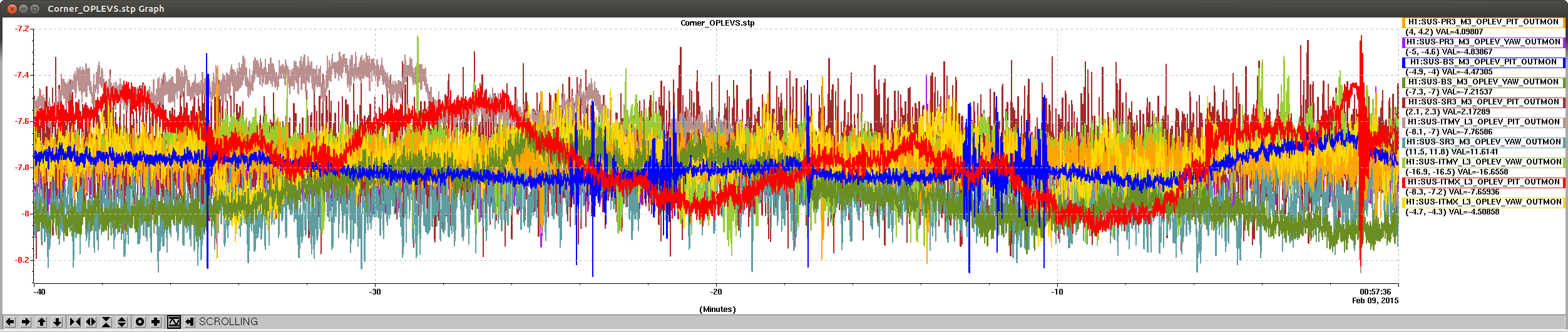
Also, the use of DHARD WFS (pitch and yaw) has removed the need for touching up the ETMs. However, since the AS36Q WFS feedback to the BS has not worked for the past couple of days, the BS had to be touched up by hand every so often.